Yale nexTouch Installation And Programming Instructions
Keypad access exit trim lock
Hide thumbs
Also See for nexTouch:
- Installation and programming instructions (31 pages) ,
- Installation and programming instructions (28 pages) ,
- Installation and programming instructions (24 pages)
Table of Contents
Advertisement
nexTouch
™
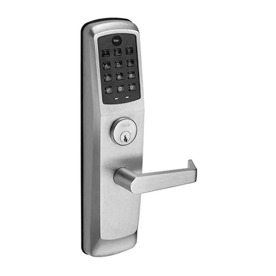
Keypad Access Exit Trim Lock
Touchscreen and Push Button
Installation and Programming Instructions
WARNING
This product can expose
you to lead which is
known to the state of
California to cause cancer
and birth defects or other
reproductiveharm.For
more information go to
www.P65warnings.ca.gov.
08/2018
Retrofitting or modifying this product may impact fire rating, safety features and warranty.
Consult with code specifications to ensure compliance with all codes and ratings.
80-8470-0900-000 04-21
Part of ASSA ABLOY
Advertisement
Table of Contents

Related Manuals for Yale nexTouch


Summary of Contents for Yale nexTouch
- Page 1 ™ Keypad Access Exit Trim Lock Touchscreen and Push Button Installation and Programming Instructions WARNING This product can expose you to lead which is known to the state of California to cause cancer and birth defects or other reproductiveharm.For more information go to www.P65warnings.ca.gov.
-
Page 2: Before You Begin
Before You Begin template Fire Guard Optional Network Module Optional Privacy DPS Switch Tools Needed Outswinging Door Left Hand Interior Right Hand Reverse Reverse Exterior #3 & #2 Face a door swinging open toward you. If it swings open to the right, it is a right hand reverse door. -
Page 3: Prepare Door
Door Position Switch Option optional Privacy DPS Switch With Door Position Switch installed and door closed, all keypad functions can be disabled by Privacy Button. Prepare Door DPS Option for Privacy Function template Wood Door: 3/8" Dia. Thru to Hole in Door Face *Metal Door: 3/4"... -
Page 4: Install Cylinder
Install Cylinder Tighten counter-clockwise to secure lock. Use key to thread cylinder. Pull key out of cylinder to first blade cut for best operation. If using cylinder other than 1-1/8", a new collar must be used that is sized appropriately for cylinder length. Test Cylinder Test cylinder by turning key counter-clockwise to unlock trim. - Page 5 Change Hand of Trim (if necessary) Left Hand Reverse Right Hand Reverse There is a spring inside spindle. Be sure to keep spring for reassembly. Spindle Tighten nut then loosen just enough that spindle tab aligns with top of hole. Be sure spring is inside spindle.
- Page 6 Install Outside Trim Assembly #10-32 x 1" OHPMS Do not take apart outside assembly. Exit Device 2 hinge side screws Mounting hold outside trim Holes assembly until exit device is installed. All 4 screws MUST be used for proper installation. Do not tighten screws until exit device...
-
Page 7: Install Exit Device
Install Exit Device #10-32 x 1" PHMS Refer to exit device installation instructions for details of device installation. Tighten all screws. Test Mechanical Lock Function by Key, Lever and Keypad 80-8470-0900-000 04-21 Part of ASSA ABLOY... - Page 8 Install Strike and Optional DPS #10-24 PFHMS DPS Option for Privacy Function Frame *Metal Frame: 3/4" Dia. x 1" See Instructions with DPS Kit *Supplied plastic collar MUST be installed for DPS to function properly. 3-1/2" Strike must be centered with exit device bolt. For proper engagement, door should remain latched and not rattle when pushed, pulled or shaken in/out.
- Page 9 Install Inside Mounting Plate #8 x 3/8" PRH #8 x 1/2" PHWS Sheet Metal Wood #10-32 x 1-1/2" THPMS Inside of Door Optional 80-8470-0900-000 04-21 Part of ASSA ABLOY...
- Page 10 Attach Cables to Inside Lock Reset Button Keypad Connection External Power Optional Connection Motor Connection 80-8470-0900-000 04-21 Part of ASSA ABLOY...
- Page 11 Install Inside Lock #8-32 x 5/16" PHMS Avoid crimping cables! Do not tighten screws until lock is flat against plate without excessive pressure. 80-8470-0900-000 04-21 Part of ASSA ABLOY...
- Page 12 Install Module (optional) Network or Yale Accentra Key Module Optional Network or Yale Accentra Key module must be installed BEFORE batteries. The Yale Accentra Key module enables access with physical (cards and fobs) and mobile credentials ONLY. Creation and use of User PIN codes are disabled.
- Page 13 Instructions to create Master PIN code before testing. Enter PIN code and press to test. Install Exit Device Cover ™ Congratulations, you've installed the Yale nexTouch Exit Trim Lock! Continue to customize your product. 80-8470-0900-000 04-21 Part of ASSA ABLOY...
-
Page 14: Programming Instructions
Programming Instructions Lock Activation On Touchscreen Lock Activation models touch Yale On Push Button logo to wake lock models touch check mark to wake lock Unlock Indicator Low Battery Indicator (Touchscreen) (Touchscreen) Lockout Mode Indicator 9 Volt Battery (Touchscreen) Override Terminal... - Page 15 Creating Master PIN Code Creating a Master PIN Code must be performed upon installation or after resetting the lock to factory default. Programming and use of lock is not possible until this step has been successfully completed. Press (Touchscreen) Press (Push Button) "Register Master Code.
- Page 16 Creating User PIN Codes Master PIN code must be created first. *Max User Codes = 500 The Yale Accentra Key module enables access with physical (cards and fobs) and mobile credentials ONLY. Creation and use of User PIN codes are disabled. Press...
- Page 17 Creating User PIN Codes con't Enter 4-8 digit PIN code followed by "Registered. Press the check key to complete. Press the gear key to continue." Adding more User Codes: To end programming: Press Press Enter 4-8 digit PIN code "Completed." Press "Registered.
- Page 18 Locking & Unlocking Door with Registered Master or User PIN Code The Yale Accentra Key module enables access with physical (cards and fobs) and mobile credentials ONLY. Creation and use of User PIN codes are disabled. Master PIN code is only used for programming and configuring lock with Yale Accentra Multi-Family configuration app and will not unlock door.
-
Page 19: Resetting Lock To Factory Default
6. While continuing to press reset button, temporarily remove one (1) AA battery. 7. Reinstall battery. 8. Release reset button and wait approximately 15 seconds. Speaker will announce "Welcome to Yale.” 9. Reinstall inside lock. 10. If utilizing a network module, remove batteries. Insert network module. Reinstall batteries. - Page 20 PIN code for duration of shut down time. The touchscreen keypad will flash and a red lock symbol will be at bottom of keypad. The push button keypad will flash and Yale icon will flash blue for shut down period. Keypad will be available after shut down time is complete.
-
Page 21: Feature Programming Through Menu Mode Using Master Pin Code
**This function available only with DPS option installed. Enable All Code Lockout Disable ***This function appears only with Yale Z-Wave network module installed. ***Network Module Setting Join the network Exit the network ***Set-up Digital Keys 80-8470-0900-000 04-21 Part of ASSA ABLOY... -
Page 22: Programming Troubleshooting
Programming Troubleshooting Symptom Suggested Action Touchscreen models become active when Yale logo is pressed. Push Button models become active when key is pressed. Lock does not respond. • Check batteries are installed and oriented correctly (polarity). There are no lights or •... -
Page 23: Hardware Troubleshooting
Hardware Troubleshooting Door is binding. a. Check that door and frame are properly aligned and door is free swinging. b. Hinges should not be loose or have excessive wear. For additional hardware troubleshooting, please refer to exit device installation instructions. Factory Settings Settings Factory Setting... - Page 24 24/7 Support Email: Support@YaleLock.com Website: Yale Commercial is a business associated with ASSA ABLOY Access and Egress US.YaleHome.com Hardware Group, Inc., an ASSA ABLOY Group company. Copyright © 2017 - 2021, Email for orders: ASSA ABLOY Access and Egress Hardware Group, Inc.
Need help?
Do you have a question about the nexTouch and is the answer not in the manual?
Questions and answers