Simrad GC80 EXPANDED Instruction Manual
Gyro compass
Hide thumbs
Also See for GC80 EXPANDED:
- Instruction manual (132 pages) ,
- User manual (121 pages) ,
- User manual (83 pages)
Table of Contents
Advertisement
Quick Links
Advertisement
Table of Contents

Related Manuals for Simrad GC80 EXPANDED


Summary of Contents for Simrad GC80 EXPANDED
- Page 1 INSTRUCTION MANUAL SIMRAD GC80/85 EXPANDED Gyro Compass 20221529C English...
- Page 2 Simrad GC80/GC85 Expanded Gyro Compass Document revisions Date Written by Checked by Approved by 08.01.04 17.02.05 05.12.05 Document history Rev. A First issue. Rev. B Updated for new software release (Master compass: V.1.03, Control unit: V.1.04). Rev. C New procedure for how to adjust true heading, updated dimensions for remote panel, other minor updates to text throughout the manual.
-
Page 3: About This Manual
About this manual This manual is intended as a reference guide for installing, operating and maintaining Simrad GC80 and GC85 Expanded Gyro compasses. The manual assumes that the operator is a qualified ship officer, or is under supervision of a qualified person. -
Page 4: System Overview
8. Drawings Outline drawings and wiring diagrams for the GC80/GC85 Expanded gyro system. 9. Spare part list List of all standard and optional units that are used in the GC80 and GC85 Expanded gyro systems. 10. Terminal layout List of all terminal pins and terminal labelling with details on GTERM board in the GC80 Control unit. -
Page 5: Table Of Contents
SYSTEM OVERVIEW............1 Introduction...............2 Precaution in use ..............3 System components............4 Bearing repeaters ...............4 USER INTERFACE ..............5 GC80 Expanded Control unit ..........6 OPERATION...............9 System Start-up and Shut-down......... 10 Start-Up ..............10 Turning the Gyro compass OFF........11 Selecting active compass ........... 12 Adjusting dimming level ............ - Page 6 Simrad GC80/GC85 Expanded Gyro Compass Balancing the Horizontal ring ........29 Replacing the Fuses ............30 Master Compass............30 Expanded Control unit..........31 INSTALLATION..............33 Unpacking and handling ............ 34 Mechanical installation ............34 Control unit ..............35 Master compass ............37 Cabling ................
- Page 7 Drawings included ............70 SPARE PART LIST............77 GC80 Expanded Gyro system ..........78 GC85 Expanded Gyro system ..........78 Optional equipment, GC80/85 Expanded system ....79 10 TERMINAL LAYOUT ............81 10.1 GTERM board ..............82 TB1 ................82 TB2 ................84 11 DIP SWITCH SETTINGS ...........87...
- Page 8 Simrad GC80/GC85 Expanded Gyro Compass Internal communication failure ........107 External bearing sensor failure ........107 LOG (serial) communication or data failure ....107 Repeater failure ............108 Failure when powering ON the gyro compass ....108 12.4 Complete alarm code list ..........109...
-
Page 9: System Overview
SYSTEM OVERVIEW SYSTEM OVERVIEW This section provides an overview of GC80 and GC85 Expanded Gyro compasses and their components. 20221529 / C... -
Page 10: Introduction
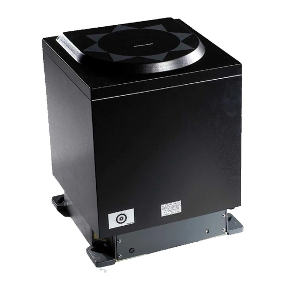
Master compass and in the Control unit. Note! A GC80 or GC85 system is identified by the labelling on top of the Master compass’ case as shown on the figure below. The labelling on the control unit is identical for both gyro systems. -
Page 11: Precaution In Use
If this happens, any external equipment depending on the bearing output from GC80/GC85 should be operated manually or switched to other bearing sensors. To assure long time safe operation, the following precautions... -
Page 12: System Components
Note! For details, refer TECHNICAL SPECIFICATION, page 63. 1.4 Bearing repeaters GC80 and GC85 outputs step and serial signals used for repeaters. Even when the gyro compass is supplied by the emergency power supply, the connected repeaters will be driven by the repeater backup function included in GC80/GC85. -
Page 13: User Interface
USER INTERFACE USER INTERFACE This section gives an overview of the GC80 Expanded Control unit and the user interface. 20221529 / C... -
Page 14: Gc80 Expanded Control Unit
The Control unit includes the control panel for the gyro compass. A flush mount kit (part number 27101757) may be ordered from Simrad for remote installation of the control panel. Refer Flush mounting the control panel, page 35. ^i^oj dvol... - Page 15 USER INTERFACE DISP Button Used for displaying data on the LCD. Refer Displaying present afpm settings, page 13. SET Button Used for changing data and input systems. Refer System start-up and software configuration, page 48 onwards. ACK/ENT Button Used for confirming a change in data and input systems. Refer System start-up and software configuration, page 48 onwards.
- Page 16 Simrad GC80/GC85 Expanded Gyro Compass THIS PAGE INTENTIONALLY LEFT BLANK 20221529 / C...
-
Page 17: Operation
OPERATION OPERATION This section describes the main operating procedure used when operating the GC80/GC85 Expanded Gyro compass. 20221529 / C... -
Page 18: System Start-Up And Shut-Down
Control panel. The following start-up sequence will mltbo be run: Control unit type (GC80 Std, or GC85 HSc), SW version for Control unit and for Master compass is displayed in rapid succession. Examples of display text are shown below:... -
Page 19: Turning The Gyro Compass Off
GYRO steady light. The GC80/GC85 will be settled within 3 hours when started with a deviation angle less than 5°. With a larger deviation angle, the compass will be settled within 4 hours. Turning the Gyro compass OFF Press the button on the Control panel. -
Page 20: Selecting Active Compass
Simrad GC80/GC85 Expanded Gyro Compass 3.2 Selecting active compass If an external heading sensor is connected to GC80/GC85, it is possible to switch between gyro and external heading sensor as active steering sensor. The gyro system will normally be used with the gyro compass selected as active compass. -
Page 21: Displaying Present Settings
OPERATION 3.4 Displaying present settings When pressing the button on the GC80 Control unit, the DISP afpm system will loop through a display sequence showing present settings for the system. - The first row in the display will show the value... - Page 22 Simrad GC80/GC85 Expanded Gyro Compass Latitude for the vessel’s current position. Value indicated as North (n) or South (s) latitude afpm NORTH LATITUDE SOUTH LATITUDE Vessel speed. GPS, Manual, Log or Serial Log may be selected as speed input system afpm Rate of turn in °/min.
-
Page 23: Confirming Present Settings
OPERATION 3.5 Confirming present settings After the GC80/GC85 is configured according to the System start-up and software configuration, described in page 48 onwards, it should not be necessary to adjust any settings when operating the gyro compass. However, if an error is reported in any of the input systems, it may be necessary to switch to a different input system. -
Page 24: Speed
Simrad GC80/GC85 Expanded Gyro Compass Speed The GC80/GC85 gyro compass calculates bearing based on the speed and latitude information that is input to the gyro system. Any errors in speed input will therefore cause incorrect true bearing from the gyro compass. - Page 25 OPERATION VESSEL HEADING (degree) 20 10 LATITUDE (degrees) 20221529 / C...
-
Page 26: Pendulum Function
Simrad GC80/GC85 Expanded Gyro Compass 3.6 Pendulum function GC80/85 software includes a pendulum function that enables the heading to be changed by 180°. The heading change is activated by closing a potential free contact connected between TB1, pin 71 and 72 on the GTERM board in GC80/85 control unit. -
Page 27: Alarm Messages
Caution When an alarm is generated, bearing information from the GC80/GC85 may not be present or may have large error. Any equipment using bearing information from the gyro compass should therefore immediately be operated according to the equipment’s emergency operating procedure. -
Page 28: Acknowledging An Alarm
Simrad GC80/GC85 Expanded Gyro Compass Acknowledging an alarm An alarm is acknowledged by pressing the button on ACK/ENT the control panel, or on an external acknowledge button is this is installed. - The audible alarm will be silenced - If the alarm situation has disappeared, the alarm lamp will... -
Page 29: Maintenance
MAINTENANCE MAINTENANCE This section holds descriptions for maintenance procedures that should be performed by the system operator. The section also includes a detailed description for how to replace the sensitive element and the fuses. 20221529 / C... -
Page 30: General
Simrad GC80/GC85 Expanded Gyro Compass 4.1 General All units in the GC80 system are designed for optimum safety and reliability. However, a limited amount of preventive maintenance should be performed to verify safe operation and durability. If any strange motion, smell, sound or heat is generated from any unit, a Simrad dealer shall be contacted. -
Page 31: Preventive Maintenance Intervals
The Sensitive element should only be replaced by authorized Simrad personnel. Note! A special tool (Simrad part no. 44174449) is required when installing the Sensitive element. This tool is delivered together with the gyro, and the sensitive element should not be installed without using this tool. - Page 32 Simrad GC80/GC85 Expanded Gyro Compass Remove the four screws securing the Sensitive element. Tilt the Horizontal ring to the side where the plug is located, and carefully remove the element from the compass. Place the defective Sensitive element in its original package, and put the rubber tube on top of the element.
- Page 33 MAINTENANCE Tilt the Horizontal ring to the side where the plug is located, and carefully put the sensitive element into the ring. - The socket on the Sensitive element should be located right above the plug attached to the Horizontal ring. Position the Sensitive element on the Horizontal ring by putting the assembly jigs into the holes as indicated on the figure below.
- Page 34 Simrad GC80/GC85 Expanded Gyro Compass Replace the assembly jigs with the two remaining screws after placing the ground wire as shown on the figure. Loosen the screw on the plug-holder on the Sensitive element, and lift the holder 2-3 mm upwards.
-
Page 35: Verifying The Element's Tilt Angle
- GC80: 15° to 19° - GC85: 18° to 22° The tilt angle is indicated on the figures below. Max and min tilt angle for GC80 std system Max and min tilt angle for GC85 High Speed system Note! The tilt angle shown above is correct for cold condition. The... -
Page 36: Parameter Updates
Parameter updates When a sensitive element is replaced, parameters for the new element have to be loaded into the GC80 Control unit before the gyro compass is started. This is done from the Extension menu as described below. Enter the Extension menu by pressing and holding the... -
Page 37: Balancing The Horizontal Ring
MAINTENANCE Exit the sub-category by pressing the button, and then exit the Extension main category by pressing and holding buttons simultaneously for at least ACK/ENT 3 seconds. For more information about the Extension menu, see ADVANCED SETTINGS, page 55 onwards. Balancing the Horizontal ring After the Sensitive element has been replaced, the gyro compass should be started as described on page 10. -
Page 38: Replacing The Fuses
Simrad GC80/GC85 Expanded Gyro Compass 4.8 Replacing the Fuses WARNING Before a fuse is replaced, ensure that both the main power and the emergency power is disconnected from the unit. Use the procedures described in the following pages when replacing the fuses. -
Page 39: Expanded Control Unit
MAINTENANCE Expanded Control unit FUSE NO CAPACITY TB-NO SIGNAL DESCRIPTION TB2-5 1R24+ Power supply for ch.1 serial repeater TB2-10 2R24+ Power supply for ch.2 serial repeater TB2-15 3R24+ Power supply for ch.3 serial repeater TB2-20 4R24+ Power supply for ch.4 serial repeater TB2-29 5R24+ Power supply for ch.5 serial repeater... - Page 40 Simrad GC80/GC85 Expanded Gyro Compass F1 - F2, F5 - F7, F9 - F11 F3, F4, F8, F13, F14 F101 F102 MAIN POWER SWITCH WARNING Make sure that the main power switch SW1 is turned OFF before any fuses are replaced!
-
Page 41: Installation
INSTALLATION INSTALLATION This section is a reference guide for correctly installing and configuring the GC80/85 Gyro Compasses. 20221529 / C... -
Page 42: Unpacking And Handling
Simrad GC80/GC85 Expanded Gyro Compass 5.1 Unpacking and handling A GC80/85 Gyro compass consist of the following units: - Master compass - Sensitive element - Control unit - Spare part kit - Mounting jigs - Documentation The sensitive element is shipped from the factory packed separately in foaming phenylethene to protect it from shock and vibration. -
Page 43: Control Unit
- 4 mounting screws - 1 blind cover In addition to this kit, an optional control panel cable must be ordered. The cable is available in three different lengths: GC80/85 - 5m (part no. 44170736) REMOTE PANEL - 10m (part no. 44170744) - 15m (part no. - Page 44 Simrad GC80/GC85 Expanded Gyro Compass Disconnect the plugs and remove the control panel’s cable. Loosen the 4 nuts holding the control panel, and remove the panel. These nuts are to be re-used when fastening the control panel to the flush mounting panel.
-
Page 45: Master Compass
INSTALLATION Master compass Select a mounting location where the deck is horizontally, flat and with little vibration, and where the pitch/roll motion is as small as possible. It is also important to select a mounting location with sufficient space for installation and service. Refer dimensional drawing, page 72. -
Page 46: Cabling
Simrad GC80/GC85 Expanded Gyro Compass Note! The foam rubber should be kept for re-use if the Master compass has to be sent to factory for service! 5.3 Cabling Note! No cables are included when the gyro system is delivered from factory. -
Page 47: Power Supply
INSTALLATION Power supply GC80/GC85 is to be supplied with 110 or 220V AC. When delivered from factory, the system is set up for 220V AC. If the system is to be supplied with 110V AC, a strap on the GPOWER board has to be added according to the figure and the table below. -
Page 48: Grounding The Units
With the exception of two switches on the SCC board in the Control unit, no switches have to be set when installing the system. These two switches are used to configure the Control unit to match type of gyro system (GC80 or GC85), and to activate an external heading sensor. Note! These dip switch settings are read when the system is started. -
Page 49: Configuring The Control Unit
Configuring the Control unit When the gyro system is shipped from factory, all dip switches in the Control unit are set as for a standard GC80 system. Before the system is started, dip switch no.2 on S1 on the SCC board has to be changed to identify the system as a GC85 system. -
Page 50: External Heading Sensor
Simrad GC80/GC85 Expanded Gyro Compass External heading sensor If an external heading sensor is connected to the GC80/GC85, dip switch no.5 on S1 on the SCC board has to be set to activate the external heading sensor. BOARD SCC board... -
Page 51: Pendulum Function
INSTALLATION Pendulum function If an external switch is connected to GC80/85 to operate the pendulum function, dip switch no.4 on S2 on the SSC board has to be set to activate the pendulum function. BOARD SCC board Pendulum function disabled... -
Page 52: Installing The Sensitive Element
Master compass according to the description below. Note! A special tool (Simrad part no. 44174449) is required when installing the Sensitive element. This tool is delivered together with the gyro, and the sensitive element should not be installed without using this tool. - Page 53 INSTALLATION ASSEMBLY JIG WITH 1 CIRCLE ASSEMBLY JIG WITH 2 CIRCLES Replace the assembly jigs with the two remaining screws. Locate the ground wire on one of the screws as shown on the figure. Loosen the screw on the plug-holder on the Sensitive element, and lift the holder 2-3 mm upwards.
-
Page 54: Verifying The Element's Tilt Angle
- GC80: 15° to 19° - GC85: 18° to 22° The tilt angle is indicated on the figures below. Max and min tilt angle for GC80 std system Max and min tilt angle for GC85 High Speed system Note! The tilt angle shown above is correct for cold condition. The... - Page 55 INSTALLATION If the tilt angle is incorrect, weight disks must be adjusted by moving weights from one side to the other. After adjustments, wait for 2 minutes before the tilt angle verification is repeated. Caution The sensitive element must have equal number of weight disks on both weight points on the tilting side (north and south side)! Carefully rotate the Horizontal ring at least one complete...
-
Page 56: System Start-Up And Software Configuration
Control panel. The following start-up sequence will mltbo be run: - Control unit type (GC80 Std, or GC80 HSc), SW version for Control unit and for Master compass is displayed in rapid succession. Examples of display text are shown... -
Page 57: Configuring The Gyro System
GYRO steady light. The GC80/GC85 will be settled within 3 hours when started with a deviation angle less than 5°. With a larger deviation angle, the compass will be settled within 4 hours. Configuring the gyro system Each Sensitive element is tuned to its Master compass before it is shipped from the factory. - Page 58 Simrad GC80/GC85 Expanded Gyro Compass Press the button again to select sub-category 1.2.F, DISP and use the arrow buttons to increase or decrease the parameter value until the value corresponds with the parameter for the new sensitive element. Confirm the entry by pressing the button.
-
Page 59: Setting The Latitude Input System
INSTALLATION Setting the Latitude input system The latitude input system may be changed during the settling process of the start-up procedure from item 7 onwards. Press the button until the display shows latitude DISP value. Press button once, and the upper line in the display starts flashing. -
Page 60: Setting The Speed Input System
Simrad GC80/GC85 Expanded Gyro Compass Setting the Speed input system The latitude input system may be changed during the settling process of the start-up procedure from item 7 onwards. Press the button until the display shows speed value DISP and speed input system. -
Page 61: Balancing The Horizontal Ring
GC80. This value is entered by using the Extension menu as follows: Activate the Extension menu by pressing and holding the... - Page 62 Simrad GC80/GC85 Expanded Gyro Compass Press the button once to display main category A-2. DISP Press the button to enter the sub-category 2.1.o. Use the arrow buttons to increase or decrease the offset parameter value. Note! To correct for +1.5°, press the Arrow Up button until the display shows 1.5°.
-
Page 63: Advanced Settings
ADVANCED SETTINGS ADVANCED SETTINGS This section gives an overview of the Extension menu, how to enter the menu and how to change parameter values. 20221529 / C... -
Page 64: General
The Extension menu holds internal parameters and communication parameters required to achieve the best possible heading accuracy on the GC80/GC85 Gyro compass. The Extension menu is grouped in 8 main categories, named A- 1 through A-8. Each of these main categories has again several sub-categories where parameter values may be set. -
Page 65: The Extension Menu Overview
ADVANCED SETTINGS MAIN MENU CHANGE / CLEAR PARA- METER VALUE afpm afpm afpm afpm NEXT MAIN NEXT SUB CATEGORY CATEGORY 6.3 The Extension menu overview Main Default Parameter/description Range Category Category value 1.1.U Damping gain 1.00 0.00 – 2.00 Determines the damping (damping operation in north- seeking motion = half cycle attenuation) and actually represents a coefficient (ratio) to the standard value stored in the software. - Page 66 Simrad GC80/GC85 Expanded Gyro Compass Main Default Parameter/description Range Category Category value 1.5.L (φ) Phi offset (°) 0.00 -3.00 – 3.00 A-1 cont. Offset value (°) around the vertical axis of gyro sphere (rotor axis) and the sensitive element. 1.6.t (θ) Theta offset (°)
- Page 67 ADVANCED SETTINGS Main Default Parameter/description Range Category Category value 2.1.o Bearing offset A (°) 0.0 – 359.9 Offset value included in the “master bearing” and used for correction of fixed error (°). If the master compass not can be mounted parallel to the vessel’s fore-after line, this parameter is used to compensate for a small mounting error.
- Page 68 Simrad GC80/GC85 Expanded Gyro Compass Main Default Parameter/description Range Category Category value A-2 cont. 2.9.G Display/setting of GPS connection bE or Non The following abbreviations are used: GPS connected Non: No GPS connected NOTE: When this value is set to “Non”, GPS can not be selected as the vessel’s input for speed and...
- Page 69 ADVANCED SETTINGS Main Default Parameter/description Range Category Category value 4.1.C GPS serial data character length 8 or 7 4.2.P GPS serial data parity bit Non, Even, 4.3.S GPS serial data stop bits 1 or 2 5.1.C LOG serial data character length 8 or 7 5.2.P LOG serial data parity bit...
- Page 70 Simrad GC80/GC85 Expanded Gyro Compass THIS PAGE INTENTIONALLY LEFT BLANK 20221529 / C...
-
Page 71: Technical Specification
TECHNICAL SPECIFICATION TECHNICAL SPECIFICATION This section list all specifications for GC80/85 gyro compass. 20221529 / C... -
Page 72: Accuracy
Follow-up speed..............> 75°/sec Gimbal freedom ........for both roll and pitch: ±45° Range of speed correction: GC80 ....0-50 knots / latitude (0° - +70°) GC85 ....0-70 knots / latitude (0° - +70°) Main power supply: ....100/110/115/200V AC, 50/60Hz Power supply for alarm and back-up: .... -
Page 73: Input Specification
TECHNICAL SPECIFICATION 7.3 Input specification Serial input signal (GPS) Circuits:..............1 Electrical: ....RS422/MNEA0183/Current loop Baud rate: ............. 4800 bps Data bits: ............8 bits Parity:..............None Stop bits: ..............1 Transmit freq.: ..........1 – 5Hz Input format: $--GGA,x,xxxx.xx,N,xx.x,E,x,~*hh<CR><LF> $--GLL,xxxx.xx,N,xxxx.xx,E,*hh<CR><LF> $--VTG,xx,T,xx,M,xx.x,N,xx,K*hh<CR><LF> Serial input signal (External heading) Circuits:..............1 Electrical: ........RS422/NMEA0183 Baud rate: .......... -
Page 74: Output Specification
Simrad GC80/GC85 Expanded Gyro Compass 7.4 Output specification Serial output signal 1 Circuits:..............10 Electrical: ..........RS422/485 When Gyro Baud rate: is selected GC80: ............4800 bps GC85 ............. 38400 bps Note! Baud Rate for GC85, refer Jumper settings on SIFC board, output serial signal selection, page 95. -
Page 75: Physical Dimensions
Height: ..............438 mm (17.2”) Width: ..............340 mm (13.4”) Depth: ..............340 mm (13.4”) Weight: ..............23 kg (51lbs) GC80 Expanded Control Unit Height: ..............495 mm (19.5”) Width: ..............364 mm (14.3”) Depth: ..............182 mm (7.2”) Weight..............14kg (31 lbs) -
Page 76: Power
Simrad GC80/GC85 Expanded Gyro Compass 7.6 Power GC80/GC85 Master Compass Voltage input: ........Supplied from Control unit GC80 Expanded Control Unit Voltage input: ............110/220V AC Backup voltage: ............... 24V DC Power consumption, including Master compass: Starting........... 1.5A at 100V AC Running:......... -
Page 77: Drawings
DRAWINGS DRAWINGS This section contains outline drawings showing mechanical dimensions of the different GC80/GC85 units, together with wiring diagrams for the gyro system. 20221529 / C... -
Page 78: Drawings Included
To scale drawings are available upon request. The following wiring diagrams are enclosed: Name Drw. no Rev. GC80/85 Gyro Compass, Expanded system. N4/N3-710185 Wiring diagram (page 1 and 2) Note! The original signed drawings are recorded at Simrad Egersund. 20221529 / C... - Page 79 DRAWINGS 20221529 / C...
- Page 80 Simrad GC80/GC85 Expanded Gyro Compass 20221529 / C...
- Page 81 DRAWINGS 20221529 / C...
- Page 82 Simrad GC80/GC85 Expanded Gyro Compass GC80 EXPANDED GC80/85 CONTROL UNIT MASTER COMPASS FGND SHIP'S SUPPLY 220/110V AC (50-60Hz) EMERGENCY SOURCE (DC24V) NOT USED BELOW IEC61162-1/-1.Ed2 CURRENT LOOP GRX+ GPS SIGNAL INPUT $--VTG MNEA GRX- $--GGA $--GLL LRX+ $--VBW LRX- SPEED LOG SIGNAL INPUT (ONE or BOTH) 200/400 pulse/n.mile...
- Page 83 DRAWINGS 20221529 / C...
- Page 84 Simrad GC80/GC85 Expanded Gyro Compass THIS PAGE INTENTIONALLY LEFT BLANK 20221529 / C...
-
Page 85: Spare Part List
SPARE PART LIST SPARE PART LIST This section includes part numbers for all standard and optional units that may be included in a GC80 and GC85 gyro system. 20221529 / C... -
Page 86: Gc80 Expanded Gyro System
27101674 GC80 Master compass 44174027 GC80 Sensitive element 27101708 GC80 Expanded Control unit 20221529 GC80/GC85 Expanded gyro compass Instruction manual 44174449 Special tool required when installing the Sensitive element 9.2 GC85 Expanded Gyro system PART NO DESCRIPTION 27101682 GC85 Master compass... -
Page 87: Optional Equipment, Gc80/85 Expanded System
SPARE PART LIST 9.3 Optional equipment, GC80/85 Expanded system PART NO DESCRIPTION GC80 Flush mounting kit in Simrad design for remote 27101757 installation of operating panel GC80 Extension cable 5 meter for remote installation of 44170736 operating panel normally mounted in Control unit... - Page 88 Simrad GC80/GC85 Expanded Gyro Compass THIS PAGE INTENTIONALLY LEFT BLANK 20221529 / C...
-
Page 89: Terminal Layout
TERMINAL LAYOUT TERMINAL LAYOUT This section includes tables which list all terminal pins and terminal labelling on GTERM board in the GC80 Expanded Control unit. The tables include detailed description for each terminal. 20221529 / C... -
Page 90: Gterm Board
Simrad GC80/GC85 Expanded Gyro Compass 10.1 GTERM board PIN NO NAME DETAILS Master compass power supply (24V DC) Master compass power supply (24V DC common) Master compass inverter alarm (over current) Master compass inverter alarm (over voltage) Master compass inverter alarm (common) Control unit –... - Page 91 TERMINAL LAYOUT PIN NO NAME DETAILS 10TSC Serial signal common 10R24- Serial repeater power supply, -24V DC 10R24+ Serial repeater power supply, +24V DC GRX+ GPS serial signal input GRX- GPS serial signal common LRX+ LOG serial signal input LRX- LOG serial signal common ESRX+ External sensor serial signal input...
-
Page 92: Tb2
Simrad GC80/GC85 Expanded Gyro Compass PIN NO NAME DETAILS EACK+ External acknowledge signal input EACK- BZSP+ Buzzer stop signal input/Pendulum BZSP- PIN NO NAME DETAILS 1TX+ Serial signal output (IEC61162-1 ed.2/-2) 1TX- 1TSC Serial signal common 1R24- Serial repeater power supply, -24V DC... - Page 93 TERMINAL LAYOUT PIN NO NAME DETAILS 5R24- Serial repeater power supply, -24V DC 5R24+ Serial repeater power supply, +24V DC 6TX+ Serial signal output (IEC61162-1 ed.2/-2) 6TX- 6TSC Serial signal common 6R24- Serial repeater power supply, -24V DC 6R24+ Serial repeater power supply, +24V DC 7TX+ Serial signal output (IEC61162-1 ed.2/-2) 7TX-...
- Page 94 Simrad GC80/GC85 Expanded Gyro Compass PIN NO NAME DETAILS ST21 Step signal (open drain signal) ST22 ST23 ST24 -24V DC for step signal output 2 ST25 +24V DC for step signal output 2 ST31 ST32 Step signal (open drain signal)
-
Page 95: Dip Switch Settings
DIP SWITCH SETTINGS DIP SWITCH SETTINGS This section includes drawings for the different printed circuits boards in the Control unit that include jumpers and dip switches. 20221529 / C... -
Page 96: Expanded Control Unit
Simrad GC80/GC85 Expanded Gyro Compass 11.1 Expanded control unit Three different boards in the Expanded control unit have jumpers and/or dip switches that may be used for configuring the GC80/85 system. Only a few of these jumpers/dip switches are used in installation and pre-running procedure for the gyro compass. -
Page 97: Gpower Board
DIP SWITCH SETTINGS GPOWER board Jumper settings on GPOWER board JUMPER DEFAULT FUNCTION DESCRIPTION Open Over-current limit set Over-current value of dc24v for Master compass is set up. Short NOTE: Should not be changed. Open Over-current limit Used for inspection at a factory. change time NOTE: Should not be changed. -
Page 98: Gterm Board
Simrad GC80/GC85 Expanded Gyro Compass GTERM board J11 J12 Jumper settings on GTERM board JUMPER DEFAULT FUNCTION DESCRIPTION Open = Two gyro systems TB3 – TB4 Gyro system Short = One gyro system 20221529 / C... -
Page 99: Scc Board
DIP SWITCH SETTINGS SCC board DIP switch settings on SCC board SWITCH DEFAULT FUNCTION DESCRIPTION S1-1 Control unit type OFF = Expanded, ON =Compact S1-2 Master compass type OFF = Standard, ON =High Speed S1-3 2 gyros used OFF = Single, ON =Dual S1-4 Active gyro system... - Page 100 Simrad GC80/GC85 Expanded Gyro Compass SWITCH DEFAULT FUNCTION DESCRIPTION SW2-1 OFF No output SW2-2 OFF S2-1 SW2-1 OFF Output for old monitor SW2-2 ON Data output for record SW2-1 ON Output for new monitor SW2-2 OFF S2-2 SW2-1 ON No output...
- Page 101 DIP SWITCH SETTINGS SWITCH DEFAULT FUNCTION DESCRIPTION OFF = Not used ON = Simrad GC type (80 or 85) shown in S3-6 For Simrad use display at start-up according to S1-2 setting. S3-7 Not used S3-8 S4-1 38400 bps Forward bow rate...
- Page 102 Simrad GC80/GC85 Expanded Gyro Compass JUMPER DEFAULT FUNCTION DESCRIPTION Output port: GTERM board, TB1 "ALCN" 1-2 Short = Alarm "CLOSES", Normal "OPEN" 3-4 short Alarm contact setting 3-4 Short = Alarm "OPEN", Normal "CLOSES" NOTE: Never use both jumpers at the same time! Output port: GTERM board, TB1 "RNCN"...
-
Page 103: Sifc Board
DIP SWITCH SETTINGS SIFC board Jumper settings on SIFC board JUMPER DEFAULT FUNCTION DESCRIPTION Output port: GTERM board, TB2: "3TX" 1-2 short = IEC61162-2 or TOKIMEC version 3-4 short 3-4 short = IEC61162-1 ed.2 Serial signal output setting Ref. page 4. NOTE: Never use both jumpers at the same time! - Page 104 Simrad GC80/GC85 Expanded Gyro Compass JUMPER DEFAULT FUNCTION DESCRIPTION Output port: GTERM board, TB2: "5TX" 1-2 short = IEC61162-2 or TOKIMEC version 3-4 short 3-4 short = IEC61162-1 ed.2 Ref. page 4. NOTE: Never use both jumpers at the same time! Output port: GTERM board, TB2: "6TX"...
- Page 105 DIP SWITCH SETTINGS JUMPER DEFAULT FUNCTION DESCRIPTION Output port: GTERM board, TB1: "10TX" 1-2 short = IEC61162-2 or TOKIMEC version 3-4 short 3-4 short = IEC-61162-1 ed.2 Ref. page 4. NOTE: Never use both jumpers at the same time! 3-4 short Output port: GTERM board, TB2: "GTX"...
- Page 106 Simrad GC80/GC85 Expanded Gyro Compass JUMPER DEFAULT FUNCTION DESCRIPTION Output port: GTERM board, TB1 "1RT~3RT" 1-2 short = Output voltage 0v to ±5v DC or 0v to ±10v "Rate of turn" Analog 1-2 short signal level selection 3-4 short = Output voltage 0v to...
- Page 107 DIP SWITCH SETTINGS JUMPER DEFAULT FUNCTION DESCRIPTION Input port: GTERM board, TB1 "ESRX" 1-2 short = Standard 3-4 short = Polarity is carried out reversely. Setting of polarity for 1-2 short "external heading NOTE: When a signal cannot sensor" signal be received by "1-2 short", it is set as "3-4 short."...
- Page 108 Simrad GC80/GC85 Expanded Gyro Compass JUMPER DEFAULT FUNCTION DESCRIPTION Output port: GTERM board, TB2 "ST1/OPRX+" 1-2 short = The step signal for "Step signal type repeater" is output. (ST1) 1-2 short 3-4 short = Serial signal receive (OPTION) (OPRX+). NOTE:...
-
Page 109: Alarm Messages And Corrective Actions
ALARM MESSAGES AND CORRECTIVE ACTIONS ALARM MESSAGES AND CORRECTIVE ACTIONS This section provides a description which system errors that are displayed, and which corrective actions that could be performed by the system operator. 20221529 / C... -
Page 110: The Alarm System
Caution When an alarm is generated, bearing information from the GC80/GC85 may not be present or may have large error. Any equipment using bearing information from the gyro compass should therefore immediately be operated according to the equipment’s emergency operating procedure. -
Page 111: Acknowledging An Alarm
ALARM MESSAGES AND CORRECTIVE ACTIONS 12.2 Acknowledging an alarm An alarm is acknowledged by pressing the button. ACK/ENT - The audible alarm will be silenced - If the alarm situation has disappeared, the alarm lamp will be switched off, and the alarm code will be removed from the LCD - If the alarm situation continues, the alarm lamp will switch from flashing to steady light. -
Page 112: Fault Finding
If none of these procedures correct the problem, contact the local Simrad dealer for advice or for requesting on board service. Before any fault finding procedure is started, the following... -
Page 113: Internal Power Failure In Control Unit
ACK/ENT If the bearing input was accepted by the system, the LCD will display current bearing without flashing. Report the error to Simrad even if the bearing is accepted and the alarm removed. 20221529 / C... -
Page 114: System Communication Failure
Simrad GC80/GC85 Expanded Gyro Compass System communication failure Alarms generated when there is a failure in communication from the Master compass to the Control unit. Turn OFF the power by pressing the button, and POWER repress the button after 20 seconds. -
Page 115: Internal Communication Failure
ALARM MESSAGES AND CORRECTIVE ACTIONS Internal communication failure Generated when the communication from the external bearing sensor has stopped ( ), or when a failure is detected in the communication ( ). Caution When these alarms are generated, the bearing information from the external bearing sensor may have large error. -
Page 116: Repeater Failure
Failure when powering ON the gyro compass If alarm code are generated simultaneously when the GC80 system is turned ON, the following procedure should be used to correct the alarm situation: Press the button to turn OFF the system, and POWER repress the button after 1 second. -
Page 117: Complete Alarm Code List
ALARM MESSAGES AND CORRECTIVE ACTIONS 12.4 Complete alarm code list Alarm Datailed Alarm content Possible cause code code Main power is When the main power (AC power source) is lost. abnormal Power is Power supply unit in the control box becomes over abnormal current. - Page 118 Simrad GC80/GC85 Expanded Gyro Compass Alarm Datailed Alarm content Possible cause code code GPS data GPS latitude data abnormal. (timeout is 17 sec.) abnormal GPS speed data abnormal.(timeout is 17 sec.) MAG/EHS When MAG/EHS system is stopped or serial signal from communication off GPS is cut.
Need help?
Do you have a question about the GC80 EXPANDED and is the answer not in the manual?
Questions and answers