Table of Contents
Advertisement
Quick Links
Advertisement
Table of Contents

Related Manuals for PR electronics 5115B


Summary of Contents for PR electronics 5115B
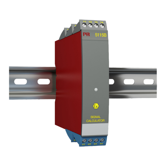
- Page 1 PERFORMANCE MADE SMARTER Product manual 5115 Signal calculator T E M P E R AT U R E I . S . I N T E R FA C E S CO M M U N I C AT I O N I N T E R FA C E S M U LT I F U N C T I O N A L I S O L AT I O N D I S P L AY...
- Page 2 6 Product Pillars to meet your every need Individually outstanding, unrivalled in combination With our innovative, patented technologies, we make signal conditioning smarter and simpler. Our portfolio is composed of six product areas, where we offer a wide range of analog and digital devices covering over a thousand applications in industrial and factory automation.
-
Page 3: Table Of Contents
Signal calculator 5115 Table of contents Warning ....................Symbol identification . -
Page 4: Warning
General mounting, wire connection and disconnection. Troubleshooting the device. VOLTAGE Repair of the device and replacement of circuit breakers must be done by PR electronics A/S only. Warning SYSTEM 5000 must be mounted on a DIN rail according to DIN 60715. -
Page 5: Safety Instructions
Should there be any doubt as to the correct handling of the device, please contact your local distributor or, alternatively, PR electronics A/S www.prelectronics.com Mounting and connection of the device should comply with national legislation for mounting of electric materials, i.e. wire cross section, protective fuse, and location. -
Page 6: How To Demount System 5000
How to demount system 5000 First, remember to demount the connectors with hazardous voltages. Picture 1: By lifting the bottom lock, the device is detached from the DIN rail. Picture 2: By lifting the upper lock and pulling the front plate simultaneously the PCB can be removed Switches and jumpers can now be adjusted. -
Page 7: Applications
Applications Redundancy measurement Output Sensor error Supply 1 sensor 2 outputs Output 1 Output 2 Supply Arithmetical operations: A + B, A - B, 2 signals of 4...20 mA A * B, and A / B A - B Transmitter B Supply 1 signal of 4...20 mA 2 outputs... -
Page 8: Application
Signal calculator 5115 • Redundancy measurement with 2 input signals • Signal calculator with four arithmetical operations • Duplication of the input signal • Input for RTD, Ohm, TC, mV, mA, and V • Universal AC or DC supply Application •... -
Page 9: Order
Order Type Version Input 5115 Standard : A RTD / TC / mV / R / mA / V ATEX Ex : B RTD / TC / mV / R mA / V / mV Input 1, RTD / TC / mV / R Input 2, mA / V / mV Example : 5115B3 NB! Please remember to order CJC connectors type 5910Ex (input 1) and 5913Ex (input 2) for TC inputs with an internal CJC. - Page 10 Accuracy, the greater of the general and basic values: General values Input type Absolute accuracy Temperature coefficient ≤ ±0.05% of span ≤ ±0.01% of span / °C Basic values Input type Basic accuracy Temperature coefficient ≤ ±4 μA ≤ ±0.4 μA / °C Volt ≤...
- Page 11 RTD and linear resistance input Input type Min. value Max. value Min. span Standard Pt46 0°C +400°C 25°C GOST 6651-59 +850°C 25°C IEC 60751 Pt100 -200°C Ni100 -60°C +250°C 25°C DIN 43760 Cu53 0°C +400°C 100°C GOST 6651-59 Linear resist. 0 Ω...
- Page 12 I.S. / Ex data for 5115B, all types Terminal 31, 32 and 33 Um ..........250 V I.S.
-
Page 13: Connections
Connections Supply: Inputs: RTD, 2-wire RTD, 3-wire RTD, 4-wire TC, internal CJC 41 42 41 42 41 42 RTD, 2-wire RTD, 3-wire RTD, 4-wire TC, internal CJC 51 52 51 52 51 52 TC, external CJC Resistance, 2-wire Resistance, 3-wire Resistance, 4-wire 41 42 41 42... - Page 14 Connections Inputs: 2-wire transmitter Current 41 42 41 42 41 42 2-wire transmitter Current 51 52 51 52 51 52 Voltage> 2.5 V Voltage <= 2.5 V Potm. via 2.5 V ref. 41 42 41 42 41 42 Voltage > 2.5 V Voltage <= 2.5 V Potm.
-
Page 15: Block Diagram
Block diagram 5115V105-UK... -
Page 16: Selection Of Input Type (5115A)
Selection of input type (5115A) Input JP 1 JP 2 JP 3 JP 4 Temperature input 1 Temperature input 2 Current / voltage input 1 Current / voltage input 2 5115 connection to Loop Link C O M Loop Link Commu- nication 5115... -
Page 17: Function Description
Function description In general Output 1 and output 2 can be configured for standard current / voltage signals in the ranges 0/4...20 mA and 0...10 VDC. When selecting the arithmetical functions, up to 4 constants, K1, K2, K3, and K4, must also be defined. The functions can be selected individually for both outputs. -
Page 18: Green Led Function
Configuration of input 2: As the signal on input 2 must be scaled by its real value, K2 must be 0. Configuration of K4: In the above example, there is no offset on the output, K4 is thus set to 0. Input 1 + K2 Division: x K3 + K4... -
Page 19: Document History
Document history The following list provides notes concerning revisions of this document. Rev. ID Date Notes 2208 Options for TC-Kr, Pt46 and Cu53 added. 5115V105-UK... - Page 20 We are near you, all over the world Our trusted red boxes are supported wherever you are All our devices are backed by expert service and a 5-year business with a global reach. This means that we are warranty. With each product you purchase, you receive always nearby and know your local markets well.
- Page 21 Benefit today from PERFORMANCE MADE SMARTER PR electronics is the leading technology company specialized in making industrial process control safer, more reliable and more efficient. Since 1974, we have been dedicated to perfecting our core competence of innovating high precision technology with low power consumption.
Need help?
Do you have a question about the 5115B and is the answer not in the manual?
Questions and answers