Table of Contents
Advertisement
Quick Links
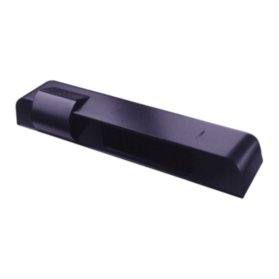
1 Description
The G3 Quick Setup Guide is for the installation and setup of the G3. This document is provided for installers and service personnel who are
familiar with the G3. For those who are not completely familiar with the installation and setup of the G3, BEA recommends following the detailed
installation and setup instructions found in the G3 User's Guide document number 75.5640.
2 Installation / Wiring / Setup
1
Mount Sensor
Drill 1/8" hole
1/4
1/2
3/4
1
1-1/4
1-1/2
1-3/4
2
1. Using scale on template, position drawing of sensor on template
0" to 2" from bottom of header.
NOTE: Flush mount with bottom of header is necessary for all
negative IR angles.
2
Cable Routing
1. With G3 in place, locate the enclosed cable and feed the stripped
end through the wire passage hole in the header.
2. Leave enough slack to allow connection to the G3 and proper
routing of wire around the plastic post.
NOTE: Observe proper routing of the cable as shown. This is
to divert rainwater from the G3 if water should run down
the cable. Proper routing of the wire also provides easier
installation of the cover.
3
Sensor Wiring
1. When connecting to a microprocessed control box, the motion output and presence output wires may be connected to separate inputs or may
also be connected to a mutual input. Some controls may only have an activation input, while others may have an activation input, as well as a
safety (or presence) input.
6 Wire Configuration (Preferred Configuration)
W
•
PWR: Red - 12 to 24 VAC / VDC: -5% to +10%
I
• PWR: Black - 12 to 24 VAC / VDC: -5% to +10%
Z
• COM: White - Common at Door Control
A
• ACTIV: Green - Activation at Door Control
R
• COM: Brown - Common at Door Control
D
• SAFETY: Blue - Safety at Door Control
4
IR Presence Sensing Field: Width and Depth (wide lens installed as default)
0°
-4°
max. 3"
max. 3"
Sensor Plastic Pin Indicator Sensor Adjustment Screw
1. The IR pattern may be adjusted by moving the pattern nearer or further away from the face of the door by adjusting the tilt angle from +4° to
-4°. A counterclockwise rotation of the adjustment screw will move the curtain further away from the door and clockwise rotation will move the
curtain toward the door. Precise location of the IR beam may be found by using BEA's Spotfinder P/N 10SPOT.
75.5641.01 20091112
COMBINED RADAR ACTIVATION AND ACTIVE INFRARED SAFETY SENSOR
Drill 1/2" wire passage hole anywhere within this area
G3 MOUNTING TEMPLATE
Drill 1/8" hole
1/4
Do not mount lower than this line
1/2
3/4
1
1-1/4
Do not mount lower than this line
1-1/2
1-3/4
2
+4°
-4°
0°
QUICK SETUP GUIDE
2. Drill hole marked for wire passage and drill pilot holes for screw
mounting. Remove template prior to sensor installation.
3. Insert mounting screws approximately halfway in and install the G3
on the screws. When in place, tighten screws to secure to header.
NOTE: Leave cover off until mechanical adjustments are complete.
Plastic Post
Cable / Wire
4 Wire Configuration (Mandatory Remote Setup: Unlock, F1, 1, Lock, Lock)
C
W
•
PWR: Red - 12 to 24 VAC / VDC: -5% to +10%
O
I
• PWR: Black - 12 to 24 VAC / VDC: -5% to +10%
N
Z
• COM: White - Common at Door Control
T
A
• ACTIV: Green - Activation at Door Control
R
R
O
D
L
Dimensions Are Approximate Size
IR Patterns
Narrow Lens Depth of Two Curtains
Narrow Lens Width of Curtains
Wide Lens Depth of Two Curtains
Wide Lens Width of Curtains
G3
C
O
N
T
R
O
L
Mounting Height of Sensor
7'
10'
12'
14'
1'3"
1'6"
1'8"
1'10"
3'6"
5'
6'
7'
1'3"
1'6"
1'8"
1'10"
6'6"
10'
12'
14'
Page 1 of 2
Advertisement
Table of Contents

Subscribe to Our Youtube Channel
Related Manuals for BEA G3


Summary of Contents for BEA G3
- Page 1 1 Description The G3 Quick Setup Guide is for the installation and setup of the G3. This document is provided for installers and service personnel who are familiar with the G3. For those who are not completely familiar with the installation and setup of the G3, BEA recommends following the detailed installation and setup instructions found in the G3 User’s Guide document number 75.5640.
- Page 2 An Assisted Setup is Required after installation and any time after mechanical IR adjustments. With remote unlock, setup (magic wand), 0. Or to perform a manual assisted set up; simply momentarily depress the right most push button on the top right of the G3. The red & green led will alternately flash approximately 16 seconds during set up.
Need help?
Do you have a question about the G3 and is the answer not in the manual?
Questions and answers