
Related Manuals for Kane 905


Summary of Contents for Kane 905
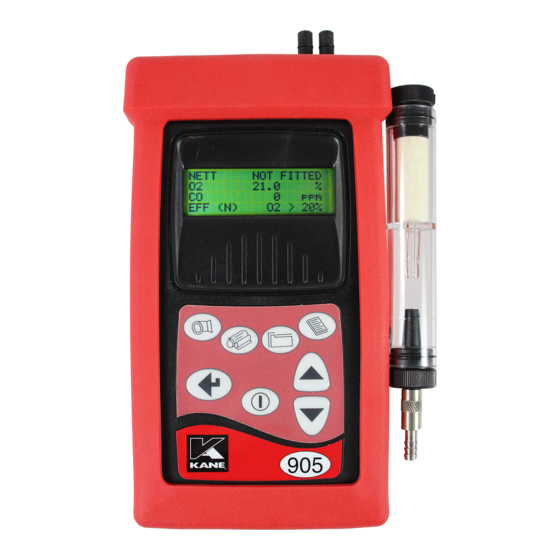
- Page 1 KANE905 Hand-held Combustion Analyser with Wireless Communication Option Stock No: 19711 July 2015 © Kane International Limited...
-
Page 2: Table Of Contents
CONTENTS Page No: 1. ANALYSER LAYOUT AND FEATURES ......... 4-8 KEY FEATURES ..................4 OPTIONS ....................4 INSTRUMENT FEATURES AND KEYPAD ..........5 INSTRUMENT LAYOUT (REAR) ............6 STANDARD PROBE CONFIGURATION ..........7 ANALYSER CONNECTIONS ..............8 2. SAFETY WARNING ..............9 3. - Page 3 CHANGING THE PARTICLE FILTER ........... 33 11. PROBLEM SOLVING ............... 34 12. ANNUAL SERVICE & RE-CERTIFY ........35-37 RETURNING YOUR ANALYSER TO KANE ......... 36 PACKING YOUR ANALYSER .............. 36 SENDING YOUR ANALYSER .............. 36 WHEN WE RECEIVE YOUR ANALYSER ..........36 SERVICE RETURNS ................
-
Page 4: Analyser Layout And Features
1. ANALYSER LAYOUT AND FEATURES KEY FEATURES Measures Temperature, Pressure, O and CO as standard. Stores 150 sets of test results. Output to IR Printer (optional). OPTIONS (CO & any two other sensors) High Range CO sensor Low Range NO sensor High Range NO sensor sensor sensor... -
Page 5: Instrument Features And Keypad
INSTRUMENT FEATURES AND KEYPAD ON/OFF Scrolls up through options ie Fuel MENU DOWN Allows access to all menu functions Scrolls down through options PUMP STORE Turns pump on and off Enters data storage menu ENTER PRINT Accepts a command ie enters a menu Prints current data option KANE905 Operators Manual... -
Page 6: Instrument Layout (Rear)
INSTRUMENT LAYOUT (REAR) NOTE: Do NOT cover exhaust port as this will severely affect analyser operation KANE905 Operators Manual Page 6... -
Page 7: Standard Probe Configuration
STANDARD PROBE CONFIGURATION KANE905 Operators Manual Page 7... -
Page 8: Analyser Connections
ANALYSER CONNECTIONS KANE905 Operators Manual Page 8... -
Page 9: Safety Warning
SAFETY WARNING This analyser extracts combustion gases that may be toxic in relatively low concentrations. These gases are exhausted from the back of the instrument. This analyser must only be used in well-ventilated locations by trained and competent persons after due consideration of all the potential hazards. -
Page 10: First Time Use
Battery Indicator. The KANE905 has a rechargeable NiMh battery which uses a different Ensure the correct charger is charger than other Kane analysers. used or damage may occur to the instrument. Check that you have all the items you have ordered. -
Page 11: Normal Start Up Sequence
During this sequence the analyser pumps fresh air into the sensors to allow toxic sensors (if fitted) to be set to zero and the Oxygen sensor to be set to 20.9 %. After switch-on the analyser will briefly display header information :- Kane International KANE905 SW19604 Version: 1.02... -
Page 12: Main Displays
To obtain the quoted specification an instrument should be calibrated with clean ambient air at standard temperature and pressure (STP). Once the time has reached zero an audible beep will be heard and NATURAL GAS will show the selected fuel on the following display:- * PRESS –... -
Page 13: Page Mode
4 PAGE MODE Use the keys to change the information that is displayed on the screen. The following pages are available: NATURAL GAS DATE 23-05-15 TIME 12:31:35 BATTERY NETT 20.9 0000 EFF (G) FLUE INLT NOT FITTED AMBIENT C 21.5 CO/CO2 0.0001 P INDEX... -
Page 14: Line Scroll Mode
LINE SCROLL MODE Line scroll mode allows you to customise the display. Use the keys to change the bottom line of the display. Once the correct line is displayed press to confirm and move the line up. Select the next parameter and repeat until all lines display the desired parameters. -
Page 15: Sampling The Flue Gas
SAMPLING THE FLUE GAS Once the automatic calibration procedure has been completed and the specific fuel has been selected (See SELECT menu) the probe can be inserted into the desired sampling point. It is recommended that the sampling point be located at least two flue diameters downstream of any bend and that the probe tip is in the centre of the flue. -
Page 16: Taking A Pressure Reading
2.00 To perform a combustion test and display draught pressure at the same time a special probe is required. Contact Kane International or Authorised Distributor for details. TAKING A FLOW READING In the UNITS menu set the pressure units to metres/sec (m/sec). These are the only units available for flow measurement. -
Page 17: Normal Shutdown Sequence
The in-line particle filter is clean and does not become blocked. NORMAL SHUTDOWN SEQUENCE DO THIS EVERY TIME YOU USE THE ANALYSER Remove the probe from the flue - TAKE CARE! THE PROBE WILL BE HOT - and allow it to cool naturally. Do not immerse the probe in water as this will be drawn into the analyser and damage the pump and sensors. -
Page 18: Moving Through The Menus
5. MOVING THROUGH THE MENUS THE MENU STRUCTURE MENU: SELECT FUEL O2 REF SMOKE RESET PITOT UNITS TEMP DISPLAY LIGHT MODE CONTRAST SETUP LANG CO MENU CALENDAR ZERO NOX % HEADER PRINT BASIC OPERATION From the MAIN DISPLAY NETT 20.9 0000... - Page 19 MAIN MENU Press to access selected Menu 1. SELECT 3. DISPLAY 2. UNITS 4. SETUP FUEL : LIGHT OIL Press to select parameter O2 Ref : OFF SMOKE : OFF RESET : NO FUEL : NATURAL GAS to change O2 Ref : OFF setting i.e.
-
Page 20: Menu Options And Settings
MENU OPTIONS AND SETTINGS MAIN MENU The MAIN MENU consists of 4 MAIN MENU sub menus: 1. SELECT 3. DISPLAY 2. UNITS 4. SETUP All sub-menus are accessed using and exited using keys move the cursor within a menu and allow parameters to be changed. - Page 21 Calculation of fuel constants are detailed in the APPENDIX. Fuel constants will have to be calculated before a user fuel can be entered. To enter the user fuel select USER FUEL 0.000 K1n : 0.000 ‘User Fuel’ and Press : 0.00 K_3 : 0.00 : 00 : 00...
-
Page 22: Sub Menu - 2. Units
level in the flue and hence dilute any toxic gas reading. Oxygen referencing gives readings as if they were undiluted. SMOKE: Allows the user to enter a smoke test number from 0-9. This value will be printed on the standard printout. Default value is OFF. -
Page 23: Sub Menu - 3. Display
PRESS.: Flue draught can be displayed in millibar (mbar), hectaPascals (hPa), millimeters water gauge (mmWG) or inches water gauge (in WG). EFF.: Efficiency can be selected for gross or net values. Gross efficiency assumes latent heat of vaporisation is lost in the boiler and hence will be lower than net efficiency. - Page 24 180 seconds drift from zero if too short a time is used. 300 seconds Kane International advise 3 minute countdown. Displayed on the Nitric Oxide unit only. NO REF: Allows the percentage P in the following 1-9% calculation to be set.
- Page 25 This screen shows the standard KANE905 header setting with the cursor YOUR COMPANY NAME & now shown underlining the K in PHONE NUMBER HERE Kane: LEFT KEY USE STORE By using any letter or number can be chosen. Once the correct character is displayed,...
- Page 26 to move right to the next. Move along until all characters spell the desired name or phone number. If you need to go back and change a character to move left. Press to return to the SET UP menu. Once an alarm has been exceeded the CO MENU: display will flash every two minutes warning the user of an alarm state and...
-
Page 27: Printing Information
The KANE905 can communicate with a PC and mobile devices. Compatibility with 2.1 for Android / PC. Please see the KANE905 software tab at: https://www.kane.co.uk/products/kane905-commercial-flue-gas-analyser Data can either be printed from a ‘live’ test or from stored data. Printing of stored data is detailed in STORING AND RETREIVING DATA. -
Page 28: Standard Printout
02>20 % EFF (G) 02>20 % EFF (N) 02>20 % LOSSES 02>20 % O2 Ref ---------------------------------------------- SOFTWARE COMPATIBILITY The KANE905 when fitted with the 2.1 module is compatible with: ANDROID: Printer App PC: KANE LIVE KANE905 Operators Manual Page 28... -
Page 29: Storing And Retrieving Data
8. STORING AND RETRIEVING DATA The KANE905 can store combustion tests. Once stored, the data can be viewed on the display or downloaded to a PC or printer. STORING A ‘LIVE’ TEST While performing a test and viewing the data on the MAIN display access the STORE menu as follows :- STORE MENU Press... -
Page 30: Deleting Data
The cursor will move to the first number, use the select the location and start printing. Press to move the cursor to the second number, select the last location to print. To print the data press . In the screen shown above locations 1 to 10 will be printed. -
Page 31: Average Of Three (Italian Version Only)
9. AVERAGE OF THREE (ITALIAN VERSION ONLY) STORING Ensure the instrument is switched on and in the main screen. In the 4- page mode below. When you are ready to store the first reading, go into the STORE menu, use the to find the “Ave Store”... -
Page 32: Printing
. You can now look at the first sample using the keys. The ‘*’s indicate that you are in the Average of Three mode and by the position of the ‘*’ which sample you are currently viewing. Press to pass to the next sample. Eventually you will be looking at the averages. -
Page 33: Maintenance
10. MAINTENANCE EMPTYING AND CLEANING THE IN-LINE WATER TRAP The in-line water trap should be checked and emptied on a regular basis. Water vapour will condense and gather in the probe line. This may move suddenly to the trap when the probe is moved. Care should be taken at all times. -
Page 34: Problem Solving
The following is a list of problems that may occur on the instrument through its operating life. If the cause of the fault is not easy to identify then we advise you contact Kane International Service Department or an International Distributor for expert advice. -
Page 35: Annual Service & Re-Certify
12. ANNUAL SERVICE & RE-CERTIFY Whilst the sensors have an expected life of more than two years in normal use it is recommended that the analyser is serviced and re-certified at least annually. This is so that long term drift on the sensors and electronics can be eliminated. -
Page 36: Returning Your Analyser To Kane
KANE905 Operators Manual Page 38... -
Page 37: Service Returns
13. PRODUCT SPECIFICATION Parameter Resolution Accuracy Range Temp Measurement Flue Temperature 0.1C/F +2.0C +0.3% reading 0-1200C/32 -2200F with suitable probe +1C +0.3% reading Inlet Temperature 0.1C/F 0-50C/32-122F Gas Measurement 0.1% +0.2% 0-25% Oxygen 1ppm +5ppm <100ppm 0-4000ppm Carbon Monoxide +20ppm <400ppm compensated +5% >400ppm 1ppm... - Page 38 Calculated KANE905 Operators Manual Page 40...
-
Page 39: Appendices
APPENDICES A. MAIN DISPLAY PARAMETERS The parameters and their meanings are detailed as follows : - DATE: Analyser date. See SET UP MENU to change TIME: Analyser time. Use SET UP MENU to change Displays the battery level from 0-100%. The analyser will BATTERY: flash RECHARGE BATTERY at less than 10% of charge. - Page 40 Temperature measured by the optional inlet air probe. INLET: This probe is plugged into the instrument through the (Ti) RS232 socket. This figure is used to calculate the NET temperature instead of AMBIENT when fitted. AMBIENT: Temperature measured by the internal sensor, used in the NET temperature calculation if an INLET probe is not (Ta) fitted.
- Page 41 Calculated total Nitric oxides displayed in ppm or mg/m3. NOx: Where NOx = NO + P%NO, note P can be set from 0-9%, default = 5%. See SELECT menu 5.2.2. Also displayed as NOx (n) referenced to oxygen. The display will read ‘O2 >...
-
Page 42: Combustion Efficiency Calculation
Since the fuel air mixture is never consistent there is the possibility of unburned/partially unburned fuel passing through the flue. This is represented by the unburned carbon loss. Losses due to combustible matter in ashes, riddlings, dust and grit, radiation, convection and conduction are not included. Efficiency Calculation: Known Data - Fuel: Qgr = Gross Calorific Value (kJ/kg) Qnet = Net Calorific Value (kJ/kg) - Page 43 Where = [(9 x H 2 + H 2 O) / Qgr] x 2425 Net Efficiency % = 100 - dry flue gas losses = 100 - 20.9 x K1n x (Tnet) / K2 x (20.9 - Gross Efficiency % = 100 - {dry flue gas losses + wet losses} = 100 –...
-
Page 44: Calculation Of Fuel Data
C. CALCULATION OF FUEL DATA For any fuel not specified by Kane International the net calorific value, gross calorific value and composition should be obtained from the fuel supplier. The following fuel data has been calculated with reference to the efficiency calculation. -
Page 45: Electromagnetic Compatability Statement
At the time of writing this manual (July 2015) Kane International Ltd are not aware of any field based situation where such interference has occurred and this advice is only given to satisfy the requirements of the Directive. -
Page 46: End Of Life Disposal
END OF LIFE DISPOSAL The Waste Electrical or Electronic Equipment (WEEE) Directive requires countries in the EU to maximise collection and environmentally responsible processing of these items. Products are now labelled with a crossed out wheeled bin symbol to remind you that they can be recycled.
Need help?
Do you have a question about the 905 and is the answer not in the manual?
Questions and answers