
Related Manuals for Kane KM9106


Summary of Contents for Kane KM9106
- Page 1 KM9106 Operators Manual Kane International Limited Kane House, Swallowfield Welwyn Garden City Hertfordshire AL7 1JG Tel: +44 (0) 1707 375550 Fax: +44 (0) 1707 393277 e-mail: sales@kane.co.uk Stock No 16958/8 February 2003 © Kane International Limited...
-
Page 2: Table Of Contents
CONTENTS Page No: 1. ANALYSER LAYOUT AND FEATURES ................... 1 1.1 Handset features ......................1 1.2 Analyser features......................2 1.3 Standard Probe Configuration..................3 1.4 Analyser connections ....................4 2. SAFETY WARNING ........................5 3. FIRST TIME USE ........................... 5 4. - Page 3 7. PRINTING INFORMATION ......................30 7.1 Changing Printout Parameters ................31 7.2 User Defined Printouts.................... 33 7.2.1 Standard Printout................... 34 7.2.2 Master List of Printed Parameters..............35 8. QUINTOX LOGGING AND PC DOWNLOAD ................36 8.1 Overview ........................36 8.1.1 Description ....................36 8.1.2 Switching the Logger on ................
-
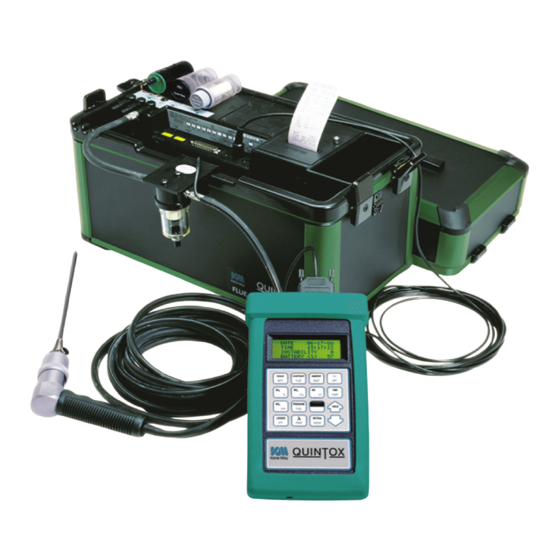
Page 4: Analyser Layout And Features
DOWN key Compartment (back) ENTER/SETCAL keys Commonly used keys ON/OFF Pages up through screens Scrolls up through options, ie Fuel ENTER & SET/CAL DOWN SET/CAL ENTER Accepts parameters Pages down through screens Enters values Scrolls down through options KM9106 Operators Manual... -
Page 5: Analyser Features
Sulphur Filter Printer unit Connection lead Particle Filter for Oxygen Battery Handset sensor enclosure (stored in pocket) Dual Accessory pressure ports storage space (leads/water Water trap trap etc.) Water trap connection located on side of instrument Instrument case KM9106 Operators Manual... -
Page 6: Standard Probe Configuration
1.3 Standard Probe Configuration KM9106 Operators Manual... -
Page 7: Analyser Connections
1.4 Analyser Connections KM9106 Operators Manual... -
Page 8: Safety Warning
When using the analyser for the first time you have the following under your control PARAMETER SECTION Display Contrast Backlight Language Line Rejection for mains frequency Gas Measurement Scale Temperature scale Pressure scale Reference oxygen Time and date Printed header name and telephone number KM9106 Operators Manual... -
Page 9: Normal Start Up Sequence
Oxygen sensor to be set to 20.9 %. After switch-on the analyser will KANE-MAY briefly display the Kane logo and TEL +44 (0) 1707 375550 telephone numbers:- FAX +44 (0) 1707 393277... - Page 10 It is advisable to repeat Oxygen Calibration every 2 hours for maximum accuracy. to change the display. NETT ..20.9 ppm . . . 0000 EFF (G) % . . . All parameters are detailed in Appendix A - MAIN DISPLAY PARAMETERS. KM9106 Operators Manual...
-
Page 11: Main Display Parameters
% . . . mbar 0.00 This screen only shows readings if optional ppm . . 0000 sensors are fitted. In this instance the SO2 ppm . . 0000 sensor is NOT FITTED. ppm . . 0000 NOT FITTED KM9106 Operators Manual... -
Page 12: Line Scroll Mode
. . 0000 ..Select next parameter. % . . . 20.9 Repeat above until ppm . . 0000 display reads desired data . . . CO/CO2 R . . 0.0001 KM9106 Operators Manual... -
Page 13: Sampling The Flue Gas
The standard probe is rated at 650°C/1202°F. Temperatures of up to 1100°C/2012°F can be accommodated using an optional high temperature probe. TIP: To conserve battery power, switch off the pump when you are not taking a measurement. Use the key to turn the pump ON and OFF. PUMP KM9106 Operators Manual... -
Page 14: Taking A Pressure Reading
To perform a combustion test and display draught pressure at the same time a special probe is required. Contact Kane International or Authorised Distributor for details. Two pressure ports are provided on the instrument for use with a Pitot tube. Contact Kane International Ltd. -
Page 15: Normal Shutdown Sequence
N.B. Maximum cable lengths must be less than 3 metres. At the time of writing this manual (January 1997) Kane International Ltd is not aware of any field based situation where such interference has ever occurred and this advice is only given to satisfy the requirements of the Directive. -
Page 16: Using The Keypad
Carbon Dioxide calculation or reading CO, Nett and XAIR to display Carbon Monoxide plus Nett, O and CO to display AUX1 and CxHy readings plus Nett and CO FUEL to display chosen fuel and its parameters to display Gross efficiency plus O and CO KM9106 Operators Manual... -
Page 17: Display Hold
. . . 0.0 # In this function only the battery level will be updated and all other parameters are frozen. This does not apply when AUTOPRINT is ON, the time and date are also updated in this mode. KM9106 Operators Manual... -
Page 18: Display Backlight And Contrast
The Pump can be toggled on or off from the handset. TO TOGGLE THE PUMP ON /OFF Press PUMP TIP: When the pump is switched off the O reading will go down as the oxygen sensor consumes the oxygen in its housing! KM9106 Operators Manual... -
Page 19: User Selectable Settings
This function allows re-set without the need to repeat the start-up routine Toxic sensor zero The CO and other optional toxic sensors can be reset to zero if KM9106 Operators Manual... -
Page 20: Time And Date
SETTING NUMBERS. Parameter Controls Options DATE: Select each number using 0 - 9 key and ENTER The cursor _ moves to each number in turn until the last number is set. DATE 26-01-97 KM9106 Operators Manual... -
Page 21: Changing A Fuel
-- -- -- -- -- -- -- -- -- -- -- -- -- Pressing the key displays FUEL STANDARD OR USER? STANDARD FUEL Parameter Controls Options Select using key and FUEL STANDARD STANDARD FUEL USER FUEL ENTER KM9106 Operators Manual... - Page 22 Select fuel type using NATURAL GAS NATURAL GAS 2 TOWN GAS ENTER LIGHT OIL HEAVY OIL COAL ANTHRACITE COKE PROPANE BUTANE GASCOR The table shown above is for the UK. Fuel lists vary depending on the country. KM9106 Operators Manual...
-
Page 23: Gross Or Nett Efficiency
Net is used in France and Germany. NOTE: Latent heat is the heat required to turn water at 100°C into steam at 100°C, i.e. a change of state from liquid to vapour without rise in temperature has taken place. KM9106 Operators Manual... -
Page 24: Scale Options
-- -- -- -- -- -- -- -- -- -- -- -- -- SET/CAL UPPER FUNCTION UPPER FUNCTION key -- -- -- -- -- -- -- -- -- -- -- -- -- Pressing the key displays SCALE SELECT LANGUAGE ENGLISH KM9106 Operators Manual... - Page 25 = milligrams per cubic meter n denotes the reading is normalised or referenced to Oxygen See Reference Oxygen in the Appendix On power up the unit will default to ppm. COMPENSATION < > < OFF > KM9106 Operators Manual...
- Page 26 CELSIUS ENTER FAHRENHEIT SET PRESSURE Parameter Controls Options Select using key and PRESSURE mbar ENTER inWG NOTE: mbar millibar inWG inches of water gauge SET REFERENCE O2 Parameter Controls Options REFERENCE Select using key and ENTER KM9106 Operators Manual...
- Page 27 P% = REF. %NOx and is set to 5% as default. With both NO and NO2 sensors fitted the formula is as follows :- • NOx = NO + NO2 SET NOx REF NOx = SUM KM9106 Operators Manual...
- Page 28 NOx = NO adds the ppm values together and then converts to NO equivalent. • NOx = NO2 adds the ppm values together and then converts to NO2 equivalent. On power up the unit will default to NOx = SUM KM9106 Operators Manual...
-
Page 29: Inlet Temperatures
-- -- -- -- -- -- -- -- -- -- -- -- -- ENTER FLUE . . . 30.0 The temperature measured by the flue probe will be set in the Quintox. Press to check the reading. INLET KM9106 Operators Manual... -
Page 30: Oxygen Calibration
-- -- -- -- -- -- -- -- -- -- -- -- -- ENTER SERVICE CODE -- -- -- -- > 0 0 0 0 < -- -- -- -- Press four times ENTER CALIBRATE SENSOR Parameter Controls Options KM9106 Operators Manual... - Page 31 Once the instability has reached zero press to accept the zero calibration ENTER and return to the main display. If the instability does not reach zero then the instrument will show FAULT. Contact Kane International or Authorised Distributor for advice. KM9106 Operators Manual...
-
Page 32: Co Alarm
This will continue until the CO level falls below the alarm setting. -- -- -- -- -- -- -- -- -- -- -- -- -- CO ALARM 410 ppm -- -- -- -- -- -- -- -- -- -- -- -- -- KM9106 Operators Manual... -
Page 33: Printing Information
CxHy % ..NETT C ..FLUE C ..INLT NOT FITTED AMBIENT 16.9 -- -- -- -- -- -- -- -- -- -- -- KM9106 Operators Manual... -
Page 34: Changing Printout Parameters
2 AUTO PRINT 2:00 minutes. keys. To select ON or OFF and press ENTER With Auto print ON the display will show :- AUTO PRINT 2:00 keys to select from 0:10 to 90:00 and press ENTER KM9106 Operators Manual... - Page 35 When the last character has been set the screen will display the next screen. Entering NO will select the standard printout as detailed earlier in this USER PRINTOUT ? section. The general principle for selecting a user printout is detailed below. KM9106 Operators Manual...
-
Page 36: User Defined Printouts
O2 % ..11.2 End the printout with a line of hashes. SET LINE ..3 # # # # # # # # # # # # # KM9106 Operators Manual... -
Page 37: Standard Printout
AMBIENT C 16.9 AMBIENT AIR TEMP - - - - - - - - - - - - DOTTED LINE Not all parameters are used. See the master list on the next page if more are required. KM9106 Operators Manual... -
Page 38: Master List Of Printed Parameters
FLUE GAS NO CONTENT FLUE GAS NOX CALCULATION FLUE GAS CO CONTENT CxHy HYDROCARBON MEASURMENT CO/H CROSS SENSITIVITY MEASUREMENT AUX1 AUXILIARY 1 SENSOR MEASUREMENT --------- DOTTED LINE # # # # # # # # STOPS PRINTOUT KM9106 Operators Manual... -
Page 39: Quintox Logging And Pc Download
A flashing cursor will be positioned over the number 1, control of the cursor is through and . Move the cursor to the desired function and press enter to select. To return to the MENU at any time press simultaneously. KM9106 Operators Manual... -
Page 40: Logging Data
Quintox charger into the side of the handset. Typical recharge time is 12 hours. Take care to insert batteries correctly, indication of polarity is in the battery enclosure. KM9106 Operators Manual... -
Page 41: Logger Control
Select YES or NO using press . A warning display is shown and you are requested to confirm you want to delete all of the data stored ! CONFIRM DELETION Select YES or NO using press ENTER KM9106 Operators Manual... - Page 42 Download Memory allows you to output the stored information to a PC, output is in our own format and requires a special program to extract the data. Contact Kane International or Distributor for information on the ‘Fireworks’ range of software.
-
Page 43: Downloading Information
Data can either be downloaded from the handset or stored directly in a PC realtime. To extract the data from the handset contact Kane International for information of the FIREWORKS range of software. The software allows information to be extracted from the handset or gather information from the PC. -
Page 44: Setting Up Your Pc
8.4.1 Setting Up Your PC A standard communications package will be able to collect the data from the Quintox. Windows Terminal software is a suitable package. The communications protocol should be set to :- KM9106 Operators Manual... -
Page 45: Capturing Data From Quintox
25 pin contact your computer supplier for a convertor. Set the logger to DOWNLOAD data and ensure it is in READY mode. NOTE: You will require batteries to run the logger and download the data. KM9106 Operators Manual... -
Page 46: Continuous Monitoring
NO2 and SO2 readings are required. A Main Purge solenoid should also be fitted to the Quintox when monitoring for longer periods of time. This is to supply fresh air to the sensors and hence prevent them drying out. See Recommended Operation in next section. KM9106 Operators Manual... -
Page 47: Main Purge
NOTE: If the analyser is positioned where levels of gases are higher than fresh air ambient conditions then auto zero should not be used. KM9106 Operators Manual... - Page 48 PURGE DURATION 05 <05 ... . 09> PURGE INTERVAL 30 <09 ... . 99> KM9106 Operators Manual...
-
Page 49: Auto Zero
The main purge will also operate when any gas concentration goes over the stated range of that sensor. Fresh air will be drawn into the Quintox until the gas level is down to 80% of the sensor range. KM9106 Operators Manual... -
Page 50: Maintenance
Clean the inside of the filter housing with a suitable soft cloth. Insert a new filter element onto the spigot on the filter end cap and carefully insert it into the filter body. KM9106 Operators Manual... -
Page 51: Charging The Battery
-- -- -- -- -- -- -- -- -- -- -- -- -- SET/CAL UPPER FUNCTION UPPER FUNCTION key -- -- -- -- -- -- -- -- -- -- -- -- -- Pressing the key displays PRINT PAPER FEED Press any key to stop. KM9106 Operators Manual... -
Page 52: Changing The Printer Ribbon
Marked on one end of the cartridge is PUSH. Gently press down on this end and the ribbon cartridge will pop up at the other end. Remove the cartridge and dispose of. Fit a new ribbon guiding the paper roll between the exposed ribbon and cartridge body. Refit printer cover. KM9106 Operators Manual... -
Page 53: Problem Solving
The following is a list of problems that may occur on the instrument through its operating life. If the cause of the fault is not easy to identify then we advise you to contact the Kane International Service Department or an International Distributor for expert advice. -
Page 54: Annual Re-Calibration
This is so that long term drift on the sensors and electronics can be eliminated. Local regulation may require more frequent re-calibration and users should check with appropriate authorities to ensure they comply with relevant guidelines. KM9106 Operators Manual... -
Page 55: How To Get Expert Help
There will be occasions when despite having read the manual there will be problems that you cannot resolve and so you need external help. Before calling Kane International or one of its International Distributors please first check the following: Find the serial number of the instrument. It is located on the label close to where the charger and handset leads plug into the analyser. -
Page 56: Product Specification
Sulphur Dioxide (SO Pressure: 0.1% +/-7% of reading +/-0.4% 0-100% Carbon Dioxide (CO 0.1% +/-0.3% +/-5% of reading Carbon Dioxide 0.01% +/-1% 0-5% Methane (LEL) Efficiency Hydrocarbons (HC): Using dry gases at STP Calculated LEL = Lower Explosive Limit KM9106 Operators Manual... - Page 57 8 Data bits, 2 Stop bits. QUINTOX Pin 2: TXD Pin 2: TXD Pin 3: RXD Pin 3: RXD Pin 4: RTS Pin 4: RTS Pin 5: CTS Pin 5: CTS Pin 7: Ground Pin 7: Ground KM9106 Operators Manual...
- Page 58 AMBIENT OPERATING RANGE 0 - 40°C (+32°F to 104°F) 20 - 80% RH non condensing Storage: 0-50°C Maximum gas temperature at sensors: Continuous +40°C Intermittent +55°C KM9106 Operators Manual...
-
Page 59: Appendices
Oxygen referencing prevents false readings being submitted, e.g. allowing more air into the boiler will increase the oxygen level in the flue and hence dilute any toxic gas reading. Oxygen referencing gives readings as if they were undiluted. KM9106 Operators Manual... - Page 60 Flue probe See Section 6.5. The air probe is plugged into the instrument through the INLET socket. This figure is used to calculate the NET temperature instead of AMBIENT when fitted. AMBIENT : Temperatrue measured by the internal sensor, used in the NET temperature KM9106 Operators Manual...
- Page 61 For more details on NOx calculation see Section 6.4 Scales. Reading can also be referenced to oxygen ppmn or mg/m3n. SO2 : Sulphur Dioxide reading in ppm or mg/m3. Displayed when Sulphur Dioxide sensor fitted. Reading can also be referenced to oxygen ppmn or mg/m3n. KM9106 Operators Manual...
- Page 62 It is an indication of the level if Hydrogen in the flue and can NOT be used as an exact level, it is only used to cross compensate the CO sensor. AUX1 : Auxilliary sensor position, to be used for future sensors. KM9106 Operators Manual...
-
Page 63: Nox Calculations
NOx reading is referenced to NO or NO referenced to NO NO in mg/m = NO in ppm multiplied by 1.34 NOx in mg/m = NO in mg/m multiplied by (1 + assumed NO percentage) KM9106 Operators Manual... - Page 64 2norm divided by (21 minus the actual O reading) mg/m n = initial reading in mg/m multiplied by (21 minus the O setting) and 2norm then divided by (21 minus the actual O reading) KM9106 Operators Manual...
- Page 65 2norm divided by (21 minus the actual O reading) mg/m n = initial reading in mg/m multiplied by (21 minus the O setting) and 2norm then divided by (21 minus the actual O reading) KM9106 Operators Manual...
-
Page 66: Combustion Efficiency Calculation
K1n = ( 255 x %Carbon in fuel )/Q net K2 = % max theoretical CO 2 (dry basis) K3 = % Wet Loss Measured Data: Tf = Flue Temperature Ti = Inlet Temperature m = % Oxygen in flue gas KM9106 Operators Manual... - Page 67 The formula for K4 is based on the gross calorific value Qgr. To obtain the loss based on net calorific value multiply by Qgr/Qnet. Since this loss is usually small this conversion has been ignored. Oxygen Reference CO(n) = CO x (20.9 - O (20.9 - O KM9106 Operators Manual...
-
Page 68: Calculation Of Fuel Data
D. CALCULATION OF FUEL DATA For any fuel not specified by Kane International the net calorific value, gross calorific value and composition should be obtained from the fuel supplier. The following fuel data has been calculated with reference to the efficiency calculation. -
Page 69: Electromagnetic Capatibility Statement
E. ELECTROMAGNETIC COMPATABILITY (CE) STATEMENT This product has been tested for compliance with the following generic standards: EN 50081-1 EN 50082-1 and is certified to be compliant Specification EC/EMC/KI/KM9106 details the specific test configuration, performance and conditions of use. KM9106 Operators Manual...
Need help?
Do you have a question about the KM9106 and is the answer not in the manual?
Questions and answers