Table of Contents
Advertisement
Advertisement
Table of Contents

Related Manuals for Kane 255


Summary of Contents for Kane 255
- Page 1 KANE255 Combustion Analyser Stock No: 19463 July 2014 © Kane International Ltd...
-
Page 2: Table Of Contents
10. EXAMPLE PRINTOUTS IN AMBIENT AIR 19-20 11. WHEN YOU FINISH USING THE METER 12. ANALYSER PROBLEM SOLVING 13. ANALYSER ANNUAL SERVICE & RE-CERTIFY 23-28 13.1 Returning your analyser to Kane 13.2 Service Returns ............. 25 14. ANALYSER SPECIFICATION ........27-28 Page 2... - Page 3 15. ELECTROMAGNETIC COMPATIBILITY 16. END OF LIFE DISPOSAL APPENDIX 1 – MAIN PARAMETERS: 30-31 APPENDIX 2 – SYMBOLS USED ON THE DISPLAY PRODUCT REGISTRATION 33-34 Page 3...
-
Page 4: Kane255 Overview
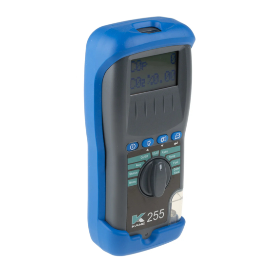
KANE255 OVERVIEW The KANE255 Combustion Analyser measures carbon dioxide (CO2), carbon monoxide (CO) and Flue temperature. It calculates oxygen (O2), CO/CO2, ratio, losses, combustion efficiency (Nett, Gross or Condensing) and excess air. In addition the KANE255 Combustion Analyser’s CO sensor checks CO levels in ambient air - useful when a CO Alarm is triggered. -
Page 5: Analyser Layout & Features
ANALYSER LAYOUT & FEATURES Page 5... - Page 6 Page 6...
-
Page 7: Batteries
1. BATTERIES Battery Type The analyser has been designed for use with disposable alkaline batteries or rechargeable Nickel Metal Hydride (NiMH) batteries. No other battery types are recommended. WARNING The battery charger unit must only be used when NIMH batteries are fitted. -
Page 8: Before Using The Analyser Every Time
2. BEFORE USING THE ANALYSER EVERY TIME: Check the water trap is empty and the particle filter is not dirty: To empty water trap, unscrew the red screw plug and re-tighten once it is empty. To change the filter, remove protective rubber cover, pull out the water trap unit from the analyser, remove the water trap’s particle filter from its’... -
Page 9: Safety Warning
The second line of the display counts down from 75 until the sensors are ready to use. If the analyser will not auto calibrate! Its sensors need to be replaced or recalibrated by Kane authorised repair centre. - Page 10 Switching off the Analyser: Press the ON/OFF button to switch the analyser OFF. The display counts down from 29 with the pump on to clear the sensors with fresh air – if the flue probe is still connected, make sure the analyser and probe are in fresh air.
-
Page 11: Using / / Buttons
Printing Data Press the SEND/PRINT button for 1 second to start the data transfer from the analyser to the infa-red printer. The analyser displays a series of bars until the transfer is completed. Press the button for 1 second again to abort the transfer. -
Page 12: Using The Rotary Dial (Starting From Menu)
8. USING THE ROTARY DIAL (STARTING FROM MENU): Select “Menu” on the rotary dial and navigate using the function buttons. = Scroll up = Scroll down = Enter ROTARY DIAL POSITIONS Rotate the dial to MENU and use the UP or DOWN and ENTER MENU keys to select the following function for change: Time –... - Page 13 ROTARY DIAL POSITIONS Displays the battery level and the number of days until STATUS calibration is due Displays up to two pages of two lines that toggle for custom setting Displays calculated Oxygen values and the calculated / Eff efficiency when O values are less than 18% EFFn, EFFg or EFFc as selected by the user.
-
Page 14: Measuring Flue Gases
9. MEASURING FLUE GASES After the countdown is finished and the analyser is correctly set up, put its’ flue probe into the appliance’s sampling point. The tip of the probe should be at the centre of the flue. Use the flue probe’s depth stop cone to set the position. - Page 15 NOTE: In accordance with BS7967 and EN50379 the value of the CO/ RATIO is shown to 4 decimal places. 0.0008 NOTE: 0.0008 is less than 0.004. → 0.0040 Many manufacture’s instructions show → this as 0.004. AUX display The AUX (auxillary) can be customised →...
- Page 16 Press the SEND/PRINT button for 1 second to print the full combustion test. Press and hold the SEND/PRINT button for approximately 2 seconds to store the combustion test in the memory. Press the BACKLIGHT key for one second to “freeze” the readings before printing.
- Page 17 Temperature display 49.2 Flue temperature ( → 14.6 Inlet temperature ( C) Normally set by → the flue probe during the fresh air purge. Press the SEND/PRINT button for 1 second to print the full combustion test. Press and hold the SEND/PRINT button for approximately 2 seconds to store the combustion test in the memory.
- Page 18 Press the SEND/PRINT button for 1 second to print the full combustion test. Press and hold the SEND/PRINT button for approximately 2 seconds to store the combustion test in the memory. Press the BACKLIGHT key for one second to “freeze” the readings before printing.
-
Page 19: Example Printouts In Ambient Air
10. EXAMPLE PRINTOUT IN AMBIENT AIR The standard printouts are: KANE255 V 1.00B YOUR COMPANY NAME & PHONE NUMBER HERE SERIAL NO. 000000000 DATE 01/07/14 TIME 12:00:08 COMBUSTION FUEL NAT GAS 20.9 00.0 ppm n 02 REF 00.0 ----------------------------------------------------- C a l . d u e o n 0 1 / 0 7 / 1 5 ----------------------------------------------------- CO/CO2 0.0000... - Page 20 NOTE: Printouts of stored readings will also include the TEST NO. below the serial number. KANE255 V 1.00B YOUR COMPANY NAME & PHONE NUMBER HERE SERIAL NO. 000000000 DATE 01/07/14 TIME 12:00:08 COMBUSTION FUEL NAT GAS 20.9 00.0 ppm n 02 REF 00.0 -----------------------------------------------------...
-
Page 21: When You Finish Using The Meter
11. WHEN YOU FINISH USING THE METER Remove its’ probe from the flue - THE PROBE WILL BE HOT - and let it cool. Do not put the probe in water which will be sucked into the meter, damaging its’ pump and sensors. When the meter’s readings return to ambient levels, switch it off. -
Page 22: Analyser Problem Solving
12. ANALYSER PROBLEM SOLVING If any problems are not solved with these solutions, contact us or an authorised repair center. Fault symptom Causes / Solutions Oxygen too high Air leaking into probe, tubing, water trap, connectors or internal to analyser. ... -
Page 23: Analyser Annual Service & Re-Certify
Welwyn Garden City in Hertfordshire Tel: 01707-375550 (the primary service centre for non-UK customers). By sending your analyser back to Kane for an annual fixed price service (check www.kane.co.uk for details) you have the opportunity to extend the warranty on your analyser to 5 years. -
Page 24: Returning Your Analyser To Kane
Once the analyser has been securely packed then your package is ready for shipment back to Kane. If you do not have an account with a courier company you can take your package to your local Post Office. It is advisable to send the package by Special Delivery so that it is insured and traceable while in transit. -
Page 25: Service Returns
13.2 SERVICE RETURNS (Simply cut out and attach to your package) Northern Service Department Kane International Ltd Gibfield Park Avenue Atherton Manchester M46 0SY Southern Service Department Kane International Ltd Kane House, Swallowfield Welwyn Garden City Hertfordshire AL7 1JG Northern Service Department... - Page 26 Page 26...
-
Page 27: Analyser Specification
14. ANALYSER SPECIFICATION (NOTE MAY BE SUBJECT TO CHANGE) Parameter Range Resolution Accuracy Temp Measurement Flue Temperature ±2°C 0-600C 0.1C ±0.3% reading Inlet Temperature +1°C 0-50C 0.1C (Internal sensor) ±0.3% reading Inlet Temperature ±2°C 0-600C 0.1C (External sensor) ±0.3% reading Flue Gas Measurement Oxygen... - Page 28 Pre-programmed Fuels Natural gas, Light Oil, Propane, Butane, LPG, Wood Pellets. Dimensions Weight 1kg / 2.2lb Handset 200mm / 7.9” x 45mm / 1.8” x 90mm / 3.5” Probe L300mm / 11.8” x Dia 6mm / 0.25”with 200mm / 7.8” long stainless steel shaft, type K thermocouple and 3m / 6ft long neoprene hose Ambient Operating +0C to +40C / 32-104F...
- Page 29 If not acceptable, adjust the meter’s position to minimize interference or switch off, if possible, the offending equipment during your test. At the time of writing this manual (July 2014) Kane International Ltd are not aware of any field based situation where such interference has occurred and this advice is only given to satisfy the requirements of the Directive.
- Page 30 APPENDIX 1 - MAIN PARAMETERS: Here are the legends used and what they mean: Oxygen reading in percentage (%) O2R: Oxygen reference setting. '----' means switched off or set to T Flue: Temperature measured by the flue gas probe in Centigrade. It displays ‘- OC -’...
- Page 31 EFF : Combustion efficiency calculation displayed in percentage either as Gross (G) or Nett (N) or Condensing Nett (C) - Use MENU to change. The calculation is determined by fuel type and uses the calculation in British Standard BS845. The efficiency is displayed during a combustion test, ‘- - - -’...
- Page 32 APPENDIX 2 - SYMBOLS USED ON THE DISPLAY CO/CO λ Excess Air Loss %: 100% minus loss % = efficiency % Flue temperature Inlet temperature ∆T Nett temperature Gross efficiency Nett efficiency Condensing efficiency - PO - Pump off -O>- Calculated oxygen greater than 18% so calculation is disabled -OC-...
- Page 33 PRODUCT REGISTRATION Please complete, detach and return to: Kane International Ltd Kane House, Swallowfield, Welwyn Garden City, Hertfordshire, AL7 1JG Your Details Name: Job Title: Company Name: Company Address 1: Address 2: Town/City: County: Postcode: Country: Phone Number: Fax Number:...
- Page 34 Your feedback is important to us, please add any additional comments you would like to make with regard to your recent Kane purchase: Thank you for completing this survey. All the information we have collected is confidential. We do not sell or share data with any other company or organisation.
- Page 35 Page 35...
- Page 36 Thank you for buying this analyser. Before use, please register on our website www.kane.co.uk Scan the QR code to go directly to Register your Product on-line or complete, detach and return the Product Registration form in this manual. Page 36...
Need help?
Do you have a question about the 255 and is the answer not in the manual?
Questions and answers