
Related Manuals for Lantronix xPico XPW100A003-01-B


Summary of Contents for Lantronix xPico XPW100A003-01-B
- Page 1 E Embed d ded D Device e Serv Integ gratio on Gui rt Number 90 0-619 vision J May y 2015...
-
Page 2: Intellectual Property
Intellectual Property © 2015 Lantronix, Inc. All rights reserved. No part of the contents of this book may be transmitted or reproduced in any form or by any means without the written permission of Lantronix. Lantronix, xPico and DSTni are registered trademarks of Lantronix, Inc. in the United States and other countries. - Page 3 FCC authorization is no longer considered valid and the FCC ID cannot be used on the final product (including the transmitter). Changes or modifications to this device not explicitly approved by Lantronix will void the user's authority to operate this device. xPico® Embedded Device Server Integration Guide...
-
Page 4: Warranty
For further details, please see the xPico OEM firmware license agreement. Warranty For details on the Lantronix warranty policy, please go to our Web site at www.lantronix.com/support/warranty. Revision History Date Rev. -
Page 5: Table Of Contents
Table of Contents Intellectual Property __________________________________________________ 2 Contacts ___________________________________________________________ 2 Disclaimer _________________________________________________________ 2 Warranty __________________________________________________________ 4 Revision History _____________________________________________________ 4 List of Figures ______________________________________________________ 6 List of Tables _______________________________________________________ 6 1. Introduction 8 About the Integration Guide ____________________________________________ 8 ... -
Page 6: List Of Figures
Figure 2-3 xPico Wi-Fi Block Diagram __________________________________ 14 Figure 2-4 Reverse-SMA to U.FL(long) (Lantronix Part Number 500-180-R) _____ 20 Figure 2-5 U.FL to U.FL Cable (Lantronix Part Number 500-181-R) ___________ 20 Figure 2-6 Reverse-SMA to U.FL(short) (Lantronix Part Number 500-182-R) ____ 21 ... - Page 7 Table 2-15 xPico Reset Signals _______________________________________ 27 Table 4-1 Absolute Maximum Ratings __________________________________ 39 Table 4-2 xPico Wired Recommended Operating Conditions _________________ 39 Table 4-3 xPico Wi-Fi Recommended Operating Conditions _________________ 40 Table 4-4 xPico Wired Technical Specification ____________________________ 41 Table 4-5 xPico Wi-Fi Technical Specification ____________________________ 42 Table A-1 Electromagnetic Emissions __________________________________ 44 Table A-2 Electromagnetic Immunity ___________________________________ 44...
-
Page 8: Introduction About The Integration Guide
1. Introduction About the Integration Guide This user guide provides the information needed to integrate the Lantronix® xPico® embedded device servers into customer-printed circuit boards. This manual is intended for engineers responsible for integrating the xPico embedded device server into their product. - Page 9 IAP device server using our Modbus firmware. User Guide Provides instructions for using the Windows® based DeviceInstaller™ User utility to configure the xPico and other Lantronix device Guide servers. Provides information on using the Windows based utility Com Port Redirector User to create a virtual com port.
-
Page 10: Functional Description
Wi-Fi device servers are extremely compact networking solution that enables Ethernet or Wireless connectivity on virtually any device with a serial interface. The included industry-proven Lantronix device server application and full IP stack allow seamless remote access to device data simplifying design integration while providing robust connectivity. -
Page 11: Xpico Features
2: Functional Description xPico Features The xPico device server contains Lantronix’s own DSTni® EX controller, with 256 KBytes of SRAM, 16 KBytes of boot ROM, and integrated 10/100 PHY. The xPico embedded device server also contains the following: 3.3-volt serial interface ... - Page 12 2: Fun nctional Descr r iption Figure 2-1 x xPico and xP Pico Wi-Fi Dim m ensions an nd Views ico Unit xPico Wi- -Fi Unit xPico® Em mbedded Dev vice Server In ntegration Gu uide...
-
Page 13: Xpico Block Diagram
2: Fun nctional Descr ription xPico Block D iagram The fo ollowing drawi ing is a block diagram of th he xPico emb bedded device e server show wing the rel ationships of the compone ents. Figure 2-2 x xPico Block D Diagram xPico®... -
Page 14: Xpico Wi-Fi Block Diagram
2: Functional Description xPico Wi-Fi Block Diagram The following drawing is a block diagram of the xPico Wi-Fi embedded device server showing the relationships of the components. Figure 2-3 xPico Wi-Fi Block Diagram xPico® Embedded Device Server Integration Guide... -
Page 15: Pcb Interface
2: Functional Description PCB Interface The xPico embedded device servers has a serial interface compatible with data rates up to 921,600 bps (in high-performance mode). The serial signals (RX, TX, RTS, CTS, and all CPs) are 3.3V CMOS logic level and 5V tolerant. The serial interface pins include +3.3V, ground, and reset. -
Page 16: Table 2-3 Xpico (Wired) Pcb Interface Signals
2: Functional Description Table 2-3 xPico (wired) PCB Interface Signals Signal Name xPico Primary Function Reset Internal Driver Pin # State Pull-up Strength Signal Ground Signal Ground Configurable I/O Input Active 56K to 122K LED1/LINK Ethernet Link LED, active low Output RTS1 Serial ready to send/ serial... -
Page 17: Table 2-4 Xpico Wi-Fi Pcb Interface Signals
2: Functional Description Signal Name xPico Primary Function Reset Internal Driver Pin # State Pull-up Strength Configurable I/O Input Active 56K to 122K Configurable I/O Input Active 56K to 122K 3.3V Input Power Configurable I/O Input Active 56K to 122K 3.3V Input Power Configurable I/O Input... - Page 18 2: Functional Description Signal Name xPico Primary Function Reset Internal Driver Pin # State Pull-up Strength /Pull- down floating No Connect No Connect No Connect WKUP System Wake Up on Rising Input, 30K to 50K Edge floating Signal Ground CTS1 Serial Clear to Send Input, 30K to 50K...
-
Page 19: Mating Connector
Note 7: It is highly recommended to connect RTS and CTS for serial port 1. Note: For integration information for Lantronix xPico Wi-Fi SMT embedded device server modules, XPC W1002 and XPC W1003 please reference the 900- 714 xPico Wi-Fi SMT Integration Guide. - Page 20 2: Fun nctional Descr ription Ante nna Type Peak G Gain Lantronix Par Vend ndor Typical Number mber PCB S Strip Antenna 1.5 to 2.5 5dBi, 2.39 Ethert ronics 00668 with 5 50mm cable to Ghz to 2 2.49 Ghz U.FL...
-
Page 21: Antenna Placement (Xpico Wi-Fi Units Only)
2: Fun nctional Descr ription Figure 2- 6 Reverse-S SMA to U.FL( (short) (Lantr tronix Part Nu umber 500-1 182-R) Anten na Place ement (x Pico Wi- -Fi Units Only) When designing the e xPico Wi-Fi module to a mating board d, it is importa ant to conside er the... -
Page 22: Table 2-7 Recommended Magnetic Modules And Combo Rj45/Magnetic Module Connectors
Due to this routing, the device could be installed or depopulated as needed. See the Lantronix app note, How to Connect a Lantronix Embedded Module to a Wired Ethernet Port for more details on Ethernet connection and routing, http://www.lantronix.com/pdf/appnotes/Connect-LTRX-Embed-Module-to-Wired-... -
Page 23: Serial Interface
2: Fun nctional Descr ription Figu ure 2-7 Ethe rnet Connec ction Exampl le (xPico wire red unit only) Serial Interfac The xP Pico and xPic co Wi-Fi embe edded device servers have e two externa al serial interfa aces. The si gnal levels on n the serial in... -
Page 24: Table 2-9 Rs232 Connections (Serial Transceiver Required)
2: Fun nctional Descr ription Figure 2-8 Serial Port E Example ble 2-9 RS232 Connections (Serial Transc ceiver Require red) xPico o Signal DCE Co onnector DTE C Connector Signa Descriptio DB25 Signal DB25 Signal (Logic RXDx RXDx TXDx Data In TXDx Data Out TXDx... -
Page 25: Usb Device Port (Xpico Wi-Fi Units Only)
2: Fun nctional Descr ription USB D Device Po ort (xPic co Wi-Fi U Units On nly) The xP Pico Wi-Fi em mbedded devi ce server has s one USB2.0 0 Full Speed D Device port interfa ces for conne ection to an u pstream USB B device. -
Page 26: Leds
2: Functional Description LEDs The xPico embedded device server contains several external signals that are intended to drive external status LEDs. The LEDs are listed below. The signals may be connected as shown in the reference schematic figure below. Note: The System LED usually remains on. -
Page 27: Reset Pins
2: Functional Description Reset Pins The xPico and xPico Wi-Fi embedded device servers have two signals for use as reset signals. Signal EXT_RESET# is a hardware controlled input signal that will reboot the xPico processor when asserted low. Signal DEFAULT# is polled by the xPico software. When DEFAULT# is asserted low for six seconds, the unit will reset the system to the default manufacturing settings and reboot the unit. -
Page 28: Evaluation Board Schematics
2: Functional l Description Evaluation Board Sch hematics Figur re 2-10 Evaluatio o n Board Schem m atic, Part 1 of 5 5 xPico® Embedde ed Device Server Integration Guide... - Page 29 2: Functional l Description Figur re 2-11 Evaluatio o n Board Schem m atic, Part 2 of 5 5 x x Pico® Embedde e d Device Server Integration Guide...
- Page 30 2: Functional l Description Figur re 2-12 Evaluatio o n Board Schem m atic, Part 3 of 5 5 x xPico® Embedde e d Device Server Integration Guide...
- Page 31 2: Functional l Description Figur re 2-13 Evaluatio o n Board Schem m atic, Part 4 of 5 5 x x Pico® Embedde ed Device Server Integration Guide...
- Page 32 2: Functional l Description Figur re 2-14 Evaluatio o n Board Schem m atic, Part 5 of 5 5 x xPico® Embedde ed Device Server Integration Guide...
-
Page 33: Mounting Instructions And Pcb Footprint
To A Access CA AD Files 1. Go http://www w.lantronix.com m/products/ca ad-visio.html. 2. Clic ck Download ere to access s the Registra d CAD files h ation Form. Figure 3-... - Page 34 3: Mounting g Instructions and PCB Foo otprint To Ins stall the x xPico or xPico W Wi-Fi Mod dule In the xPico embed dded device s erver develop pment kit (par rt number XP C100100K-02 and xP Pico Wi-Fi dev velopment kit t (XPW10010 00K-01), the x...
- Page 35 3: Mounting g Instructions and PCB Foo otprint Figure 3-2 A ligning Moun nting Clip Le egs to Stand doff Holes 6. Inse ert the white c clip legs furth hest from the J J1 connector r first and gen tly push down n on xPico modul...
- Page 36 3: Mounting g Instructions and PCB Foo o tprint Figure 3-3 3 Mounting Instructions s for PEM Sta andoff xPico® Em mbedded Dev v ice Server In ntegration Gu uide...
- Page 37 3: Mounting g Instructions and PCB Foo o tprint igure 3-4 Hir rose Connec ctor Layout xPico® Em m bedded Dev vice Server In ntegration Gu uide...
-
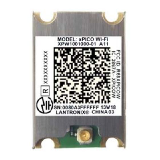
Page 38: Product Information Label
MAC address Figure 3-5 x xPico Produ uct Label Part Numb AC Address Revisi Manufactur ring Date Co Prod uct Model Lantronix Coun ntry of Origin Datamat trix Barcode gure 3-6 xPic co Wi-Fi Pro duct Label Revision Num mber Canad... -
Page 39: Specifications Electrical Specifications
4: Specifications 4. Specifications Electrical Specifications Caution: Stressing the device above the rating listed in this table may cause permanent damage to the xPico embedded device server. Exposure to Absolute Maximum Rating conditions for extended periods may affect the xPico unit’s reliability. -
Page 40: Table 4-3 Xpico Wi-Fi Recommended Operating Conditions
4: Specifications Table 4-3 xPico Wi-Fi Recommended Operating Conditions Parameter Symbol Typical Units Supply Voltage 3.15 3.46 Supply Voltage Ripples CC_PP TX Power @ 16.5dBm, 802.11b, 11Mbps TX Power @ 15dBm, 802.11g, 6Mbps TX Power @ 13dBm, 802.11g, 54Mbps TX Power @ 14.5dBm, 802.11n, MCS0 TX Power @ 12dBm, 802.11n, MCS7 RX Power @ 802.11b, 11Mbps RX Power @ 802.11g, 54Mbps... -
Page 41: Technical Specifications
Metal shell Temperature Operating range: -40°C to +85°C (-40°F to 185°F) Warranty For details on the Lantronix warranty policy, go to our web site at www.lantronix.com/support/warranty. Included Software Windows 98/NT/2000/XP-based Lantronix® DeviceInstaller™ configuration software and Windows based Com Port Redirector EMI Compliance See A:Compliance. -
Page 42: Table 4-5 Xpico Wi-Fi Technical Specification
4: Specifications Table 4-5 xPico Wi-Fi Technical Specification Category Description CPU, Memory Cortex M3 CPU, 1MB Flash, 128KB+4KB SRAM, Additional 1MB on board Flash Firmware Upgradeable via TFTP and serial port WLAN Standards 802.11 b/g/n Wireless LAN with external antenna Antenna Connector U.FL connector for external antenna Frequency Band... - Page 43 Operating range: -40°C to +85°C (-40°F to 185°F) with use of heat pad between module and mating PCB Warranty For details on the Lantronix warranty policy, go to our web site at www.lantronix.com/support/warranty. Included Software Windows 98/NT/2000/XP-based DeviceInstaller configuration software...
-
Page 44: A: Compliance (Xpico Embedded Device Server)
Compliance (xPico Embedded Device Server) (According to ISO/IEC Guide 22 and EN 45014) Manufacturer’s Name & Address: Lantronix, Inc. 7535 Irvine Center Drive, Suite 100, Irvine, CA 92618 USA Declares that the following product: xPico® Embedded Device Server Product Name Model:... - Page 45 Figu ure A-1 Certifi cate of Compli iance for Halog g en Free Manu ufacturer’s C Contact: Lantro onix, Inc. 7535 I rvine Center Drive Suite 1 Irvine, CA 92618 U Tel: (8 800) 526-876 Tel: (9 949) 453-399 Fax: (9 949) 453-399 xPico®...
-
Page 46: B: Compliance (Xpico Wi-Fi Embedded Device Server)
omplia ance (x xPico W Wi-Fi E Embed dded D Device Serv ver) According to I SO/IEC Guid de and EN 45 014) Manufacturer 's Name & A Address: antronix, Inc. 535 Irvine Ce enter Drive, S uite 100, Irvin ne, CA 92618 8 USA Declares that t... -
Page 47: Table B-2 Country Transmitter Ids
øvrige relevan te krav i direkti 1999/5/EF. Deutsch [ German] Hiermit erkl lärt Lantronix, I Inc., dass sich das Gerät xPic co Wi-Fi in Übereinstim mmung mit den n grundlegende en Anforderung gen und den üb brigen einschlägig... - Page 48 Español [S Spanish] Por medio d de la presente . declara que e el xPico Wi-Fi c cumple Lantronix, Inc. con los requ uisitos esencia ales y cualesqu uiera otras disp posiciones aplic cables o exigibles de la Directiva a 1999/5/CE.
- Page 49 Federal Communication Commission Interference Statement This device complies with Part 15 of the FCC Rules. Operation is subject to the following two conditions: (1) This device may not cause harmful interference, and (2) this device must accept any interference received, including interference that may cause undesired operation. This equipment has been tested and found to comply with the limits for a Class B digital device, pursuant to Part 15 of the FCC Rules.
- Page 50 Manual Information To the End User The OEM integrator has to be aware not to provide information to the end user regarding how to install or remove this RF module in the user’s manual of the end product which integrates this module.
- Page 51 Tant que les 2 conditions ci-dessus sont remplies, des essais supplémentaires sur l'émetteur ne seront pas nécessaires. Toutefois, l'intégrateur OEM est toujours responsable des essais sur son produit final pour toutes exigences de conformité supplémentaires requis pour ce module installé. IMPORTANT NOTE: In the event that these conditions can not be met (for example certain laptop configurations or co-location with another transmitter), then the Canada...
-
Page 52: Table B-5 Approved Antenna(S) List
Under Industry Canada regulations, this radio transmitter may only operate using an antenna of a type and maximum (or lesser) gain approved for the transmitter by Industry Canada. To reduce potential radio interference to other users, the antenna type and its gain should be so chosen that the equivalent isotropically radiated power (e.i.r.p.) is not more than that necessary for successful communication. - Page 53 Figu ure B-1 Certifi cate of Compli iance for Halog g en Free Manuf facturer's Co ontact: Lantro onix, Inc. 7535 I rvine Center Drive Suite 1 Irvine, CA 92618 U Tel: 9 49-453-3990 Fax: 9 49-453-3995 xPico® Em mbedded Dev vice Server In ntegration Gu uide...
- Page 54 RoHS Notice All Lantronix products in the following families are China RoHS-compliant and free of the following hazardous substances and elements: Lead (Pb) Mercury (Hg) Polybrominated biphenyls (PBB) Cadmium (Cd) Hexavalent Chromium (Cr (VI))
Need help?
Do you have a question about the xPico XPW100A003-01-B and is the answer not in the manual?
Questions and answers