
Related Manuals for LINET PURA


Summary of Contents for LINET PURA
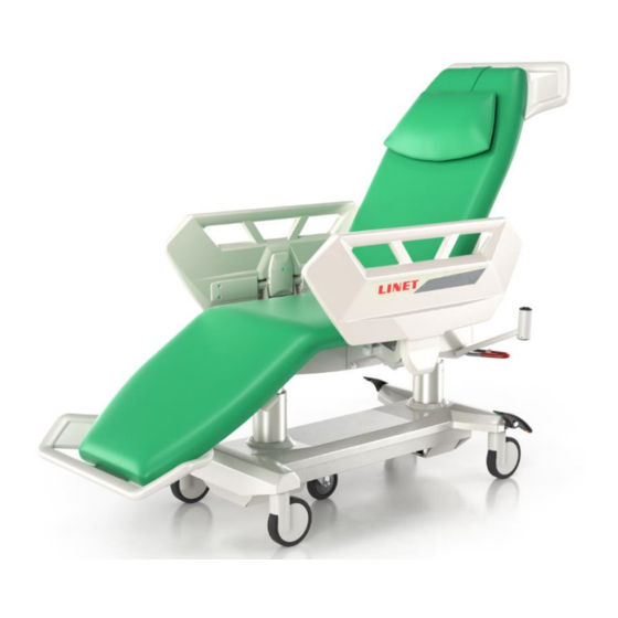
- Page 1 SERVICE MANUAL PURA Multifunctional chair D9S001ODA-0101 Version: 01 Date of publication: 2019-06...
- Page 2 Multifunctional chair PURA Author: LINET, s.r.o. Related links: www.linet.com Copyright © LINET, s.r.o., 2019 Translation © LINET, 2019 All rights reserved. Any and all trademarks and brands shall be the property of their respective owners. The man- ufacturer reserves the right to amend the content of this manual in terms of technical requirements of the product.
-
Page 3: Table Of Contents
1 SERVICE AND REPAIRS ..........................5 Caution........................5 Warranty ......................... 5 Standards ........................ 6 External parts of the product ................... 6 PRODUCT IDENTIFICATION ........................ 7 Nameplate ....................... 7 List of basic versions ....................8 List of colour versions ....................8 Identification of chair sides .................. - Page 4 Rest area frame .....................31 Control unit and power unit..................32 5.7.1 Technical parameters: ..................32 5.7.2 Description of main functions ................33 5.7.3 Sound signals:....................34 5.7.4 Block diagram of the control unit: ..............35 5.7.5 Control unit dismounting: .................36 5.7.6 ACP Controller ....................37 5.7.6.1 Light signals using LEDs ................43 5.7.6.2 Lifting column and accelerometer calibration ..........44...
-
Page 5: Service And Repairs
1.1 Caution All service inspections, safety and technical inspections or service action may be carried out exclusively by the technician trained by LINET s.r.o. Diagrams, product part lists, descriptions or other information intended to assist service staff in repairs of product parts repairable by service staff as identified by the manufacturer are available from manufacturer upon request. -
Page 6: Standards
1.3 Standards The product complies with requirements of valid standards EN 60601-1 ed. 2 and IEC 60601-1-2 ed. 3. According to the current version of Directive on Medical Instrumentation 93/42/EEC, the chair is classified as “class I medical device” without the measurement fea- ture. -
Page 7: Product Identification
2 Product identification 2.1 Nameplate The nameplate is located on the right outer side of the seat framework Type Manufacture date Serial number designation (Year-Month-Day) Manufacturer address 1D bar code EAN128 Symbols (serial number) Specification electro Meaning of type designation: ODA-XYZ0 X –... -
Page 8: List Of Basic Versions
2.2 List of basic versions ODA-AX Basic type 2.3 List of colour versions Substituted by letter “X”. A – Violet M – Yellow B – Blue P – Orange F – Green 2.4 Identification of chair sides Left Head Legs Right 2.5 Symbols Pictogram... - Page 9 Pictogram Meaning Applied parts of type B Applied parts of type BF Serial number Symbol for discontinuous operation – it means that if the product is continuously used for the period of “x”, it may not be used then for the period of “y”. For example, int x/y int 10 / 20 means that after 10 minutes of use / continuous positioning the product may not be used / positioned for the period of 20 minutes.
- Page 10 Pictogram Meaning Symbol for transport Symbol for “air pressure”. Symbol in accordance with Directive 2002/96/CE (Waste Electrical and Electronic Equipment Directive). Symbol for “Do not dispose of this product in the local collection points for waste electrical and electronic equipment”. Recycling sign GO BUTTON STOP BUTTON...
-
Page 11: Parameters
3 Parameters 3.1 Technical parameters Support area 2123 ± 3 mm Total length of the support area 965 ± 2 mm Length of the backrest 528 ± 2 mm Length of the sitting section 630 ± 2 mm Length of the foot section 590 –... -
Page 12: Electrical Parameters
3.2 Electrical parameters Battery – backup 24V/1.2 Ah Voltage – input power 100/110/120/127/240 V* Frequency 50/60 Hz Motor voltage 24 V Protection against water penetration IPX4 Device protection class Classification of the used parts Maximum power input 370 VA Pb AKU 2 x 12 V / 1.2 Ah / Battery Fuse 15A *Depending on the power supply unit used... -
Page 13: Components
5 Components 5.1 Underframe 1 - Underframe cover 2 - Underframe base 3 - Fifth castor 4 - 150 mm braked castor 4a - 150 mm directional castor (version without the fifth castor) 5 - 150 mm antistatic castor 6 - Brake pedal – right 7 - Brake pedal –... -
Page 14: Castors And Controlling Brake Pedals
5.1.1 Castors and controlling brake pedals 1 - Brake pedal – right 2 - Brake pedal –left 3 - Brake control rod 4 - 150 mm braked castor 4a - 150 mm directional castor (version without the fifth castor) 5 - 150 mm antistatic castor 6 - Insert 7 - Brake lever 8 - Hexagon 1... -
Page 15: Dismounting
5.1.1.1 Dismounting 1. Unscrew the lock screw of the brake lever and remove the lever (1) (Fig. 6.1.1.1.) 2. Loosen the nut of the brake control rod (2) (Fig. 6.1.1.1.2) 3. Push out the hexagon by about 15 cm (3), unscrew the screws locking the castor (4) (Fig. -
Page 16: Fifth Castor
5.1.2 Fifth castor 1 - Girder bracket 1 of 5th castor 2 - Girder bracket 2 of 5th castor 3 - Control rod lock of the 5th castor 4 - Spring bracket 5 - Spring 6 - Arm 7 - Arresting lever 8 - Castor lock 9 - Castor holder 10 - 125 mm castor... -
Page 17: Dismounting
5.1.2.1 Dismounting: 1. Unscrew locking screws (1) and remove the weight (Fig. 6.1.2.1.1) 2. Pull out the cotter pin (2) and remove plastic washers (3) and the spring (4) (Fig. 6.1.2.1.2) 3. Push out the draw bar of the 5th castor brake from the control rod 4. -
Page 18: Lifting Columns
5.2 Lifting columns 4-6 Nm 4-6 Nm 8-10 Nm 7-10 Nm 8-10 Nm 7-10 Nm 1 - Underframe base 2 - Foot lifting column 3 - Head lifting column 4 - Collar 5 - Lower plate 6 - Head column yoke 7 - Column screw washer 5.2.1 Head column 5.2.1.1 Technical parameters... - Page 19 4. If the column may be positioned, disconnect the foot lifting column (connector No. 4) and position the head lifting column in the lowest position, then disconnect connector No. 5 from the control unit 5. Loosen the column collar (3) (Fig. 6.2.1.2.3) 6.
-
Page 20: Foot Column
5.2.2 Foot column 5.2.2.1 Technical parameters Coverage: IP54 Input voltage: Maximum current: 5.5A Load factor: 10%, Max. 2min on/ Min. 18min off Maximum pressure load: 2000N Maximum tensile load: 500N 5.2.2.2 Dismounting 1. Remove the cover of the control unit (Chapter 6.7.5, paragraphs 1 and 2) 2. - Page 21 Figure 6.2.2.2.3 Figure 6.2.2.2.4 Figure 6.2.2.2.5...
-
Page 22: Rest Area Upholstery
5.3 Rest area upholstery 1 - Back section upholstery 2 - Seat upholstery 3 - Back section cover 4 - Back cover holder – right 5 - Back cover holder – left 6 - Rear handle 7 - Cable holder 8 - Hook 9 - Front handle... -
Page 23: Back Section Upholstery
5.3.1 Back section upholstery 5.3.1.1 Dismounting: 1. Use wide flat bladed screwdriver to remove covers (1) (Fig. 6.3.1.1.1) 2. Unscrew (2) and remove the handle of the back section (Fig. 6.3.1.1.2) 3. Unscrew (3) and remove the plastic handle of the back section (Fig. 6.3.1.1.2) 4. -
Page 24: Seat Upholstery
5.3.2 Seat upholstery 5.3.2.1 Dismounting: 1. Unscrew locking screws (1) and remove the foot bumper (Fig. 6.3.2.1.1) 2. Unscrew locking screws of upholstery (2) and remove upholstery (Fig. 6.3.2.1.2) Figure 6.3.2.1.1 Figure 6.3.2.1.2... -
Page 25: Rest Area Drives
5.4 Rest area drives 1 - Rest area frame 2 - Back section drive 3 - Foot section drive 5.4.1 Back section drive 5.4.1.1 Technical parameters Drive with CPR Coverage: IP54 Input voltage: Maximum current: Load factor: 10%, Max. 2min on/ Min. 18min off Maximum pressure load: 10000N Drive without CPR... -
Page 26: Dismounting Of The Drive With Cpr
5.4.1.2 Dismounting of the drive with CPR 1. If the back section motor is not in its lowest position and manual or controlled positioning is impossible, secure the back section appropriately 2. Remove the cover of the control unit (Chapter 6.7.5, paragraphs 1 and 2) 3. -
Page 27: Cpr Mechanism
5.4.1.3 CPR mechanism 1 - Back section drive with CPR 2 - CPR Bowden 3 - Adjusting screw 4 - Wire 5 - Bowden holder 6 - CPR handle 5.4.2 Foot section drive 5.4.2.1 Technical parameters Coverage: IP54 Input voltage: Maximum current: Load factor: 10%, Max. -
Page 28: Dismounting
5.4.2.2 Dismounting 1. Remove the cover of the control unit (Chapter 6.7.5, paragraphs 1 and 2) 2. Disconnect motor from the control unit (connector 7) 3. Remove the retaining ring (1) and pull out the motor pin (2) (Fig. 6.4.2.2.1) 4. -
Page 29: Footrest
5.5 Footrest 1 - Foot section frame 2 - Footrest drive 3 - Footrest frame 4 - Slide rail 5 - Footrest 6 - Casing 7 - Latch 8 - Corner insert 9 - Bearing box 5.5.1 Footrest drive 5.5.1.1 Technical parameters Coverage: IP54 Input voltage:... -
Page 30: Dismounting
5.5.1.2 Dismounting 1. Remove the cover of the control unit (Chapter 6.7.5, paragraphs 1 and 2) 2. Disconnect motor from the control unit (connector 8) 3. Remove Starlock (1) and pull out motor pin (2) (Fig. 6.5.1.2.1) 4. Remove the retaining ring (3), pull out the motor pin (4) and remove footrests (Fig. 6.5.1.2.2) Figure 6.5.1.2.1 Figure 6.5.1.2.2... -
Page 31: Rest Area Frame
5.6 Rest area frame 1 - Back section frame 2 - Upper frame 3 - Foot section frame 4 - Control unit 1 panel 5 - Control unit cover 6 - Head column yoke 7 - Column screw washer 8 - Cable 1 holder 9 - Cable 2 holder 10 - Upper frame cover 11 - Slide... -
Page 32: Control Unit And Power Unit
5.7 Control unit and power unit Labelling: PB53 ODA control unit: DB-F-00170 Power supply unit for PB53 ODA: DB-F-0024X where X = 0 for 230V X = 1 for 100V X = 2 for 110V X = 3 for 120V X = 4 for 127V 5.7.1 Technical parameters: Nominal supply voltage:... -
Page 33: Description Of Main Functions
Statistical values, overload and non-standard condition The control unit stores: values, calibration values, list of features and condi- tions accessed *Can drop to 20V under load. Disturbing peak voltage generated by the lifting unit can be max. 60 V. The current peak when starting the motor can take up a maximum of 15A at 42V and it should drop to the maxi- mum value of permanent current consumption in 0.5s. -
Page 34: Sound Signals
Leakage resistance and short circuit measurement – ACP controller contains a RC cell, if the function is disabled, the value of resistance is close to infinity. The value of resistance changes to 390Ω upon pressing the button and the function is considered valid and exe- cuted. -
Page 35: Block Diagram Of The Control Unit
5.7.4 Block diagram of the control unit: Connector for connection Underframe earthing Fixed connection Back Foot Foot Foot Head section rest section lamp column Control- column motor motor motor repro repro repro Lead-in cable plug repro repro repro repro DIN 8 not used DIN 13 repro... -
Page 36: Control Unit Dismounting
5.7.5 Control unit dismounting: 1. Unscrew (1) and remove the control unit cover (Fig. 6.7.5.1) 2. Unscrew (2) and remove connector cover (Fig. 6.7.5.2) 3. Disconnect all connectors 4. Unscrew control unit screws (3) and remove it (Fig. 6.7.5.3) 5. If the control unit is replaced, it needs to be calibrated (Chapter 6.7.6.2) Figure 6.7.5.1 Figure 6.7.5.2 Figure 6.7.5.3... -
Page 37: Acp Controller
5.7.6 ACP Controller ACP controller versions: Version with 4 motors without a battery Version with 4 motors with a battery Version with 5 motors without a battery Version with 5 motors with a battery... - Page 38 ACP controller functions: Buttons 1 and 2 – back section up/down: Retraction (1) and extension (2) of the back sec- tion drive. Full extension/retraction is given by the end position of the drive.
- Page 39 Buttons 3 and 4 – chair up/down: Simultaneous extension (3) and retraction (4) of lifting columns. Full extension/retraction is given by the end position of the column. If one of the columns reaches its end position earlier, other column continues extension/retraction until the button is released or end position reached.
- Page 40 Buttons 7 and 8 – tilt forward/backward: Retraction (7) / extension (8) of the foot column + extension (7) / retraction (8) of the head column. If any of the columns reaches its end posi- tion, only the second column moves until the button is released or min. 0° or max. 12° of the seat tilt is reached.
- Page 41 Button 11 – preprogrammed lying position: It the seat angle is 0°, the back section drive starts retracting + foot section starts extending until the button is released or end positions are reached. If the angle is different, the foot column starts retracting + the head column starts extending until the button is released or 0°...
- Page 42 Button 15 – Trendelenburg: The back section retraction + foot section drive extension until the button is released or their end positions are reached. Foot column extension + head column retraction until the button is released or 12° angle of seat tilt is reached.
-
Page 43: Light Signals Using Leds
5.7.6.1 Light signals using LEDs LED 1: continuous light – the keyboard is active (using GO button (14)) flashing – positioning attempted using inactive keyboard No light – the keyboard is not activated LED 2: continuous light – positioning functions are locked flashing 0.5s/0.5s –... -
Page 44: Lifting Column And Accelerometer Calibration
5.7.6.2 Lifting column and accelerometer calibration Replaced lifting column or control unit need to be calibrated in order to synchronize column positioning and determine correct chair tilt angle. Before calibration takes place, control unit must be installed correctly. 1. Hold the combination of the buttons to position the foot section (9), (10) and the but- ton of the pre-programmed lying position (11), before LED 2 and LED 4 start flashing (approx. -
Page 45: Power Unit Dismounting
5.7.7 Power unit dismounting: 1. Disconnect the chair from power supply 2. Remove the control unit (Chapter 6.7.5) 3. Remove supply cable catch (1) and disconnect it from the power unit (Fig. 6.7.7.1) 4. Unscrew the power source screws (2) and cut the lacing course (3) (Fig. 6.7.7.2) 5. -
Page 46: Power Unit Fuses
5.7.7.1 Power unit fuses 1. Dismount the power unit (Chapter 6.7.7) 2. Unscrew bayonet caps of fuses (1) (Fig. 6.7.7.1.1) 3. Replace fuses according to the power unit type (2) (Fig. 6.7.7.1.2) T1.6AL for 230V; T3.15AL for 100-127V Figure 6.7.7.1.1 Figure 6.7.7.1.2 5.8 Siderails 1 - Siderail body... - Page 47 Siderail mechanism 1 - Siderail closure 2 - ABS cover 3 - Siderail holder 4 - Siderail holder panel 5 - Siderail arm 6 - Slide bearing 1 7 - Siderail draw bar 8 - Slide bearing 2 9 - Slide bearing 10 - Latch 11 - Arm 12 - Hydraulic damper...
-
Page 48: Armrests
5.9 Armrests 1 - Armrest arm –left 2 - Armrest arm –right 3 - Armrest axis 4 - Back stop 5 - Arm 1 6a - Arm 2 – left 6b - Arm 2 – right 7 - Axis of armrest arm 8 - Securing panel Armrest arm: 1 - Armrest upholstery... -
Page 49: List Of Tools And Equipment Necessary To Service The Chair
6 List of tools and equipment necessary to service the chair Tools Gola set Screwdriver set Wrench set Socket head bits Torx bit set Allan wrench set Knife Set of pliers Torque wrench Hammer, plastic stick Metre Multimetre...
Need help?
Do you have a question about the PURA and is the answer not in the manual?
Questions and answers