Advertisement
D 10 Quick Start Guide
M
Appearance & Installation
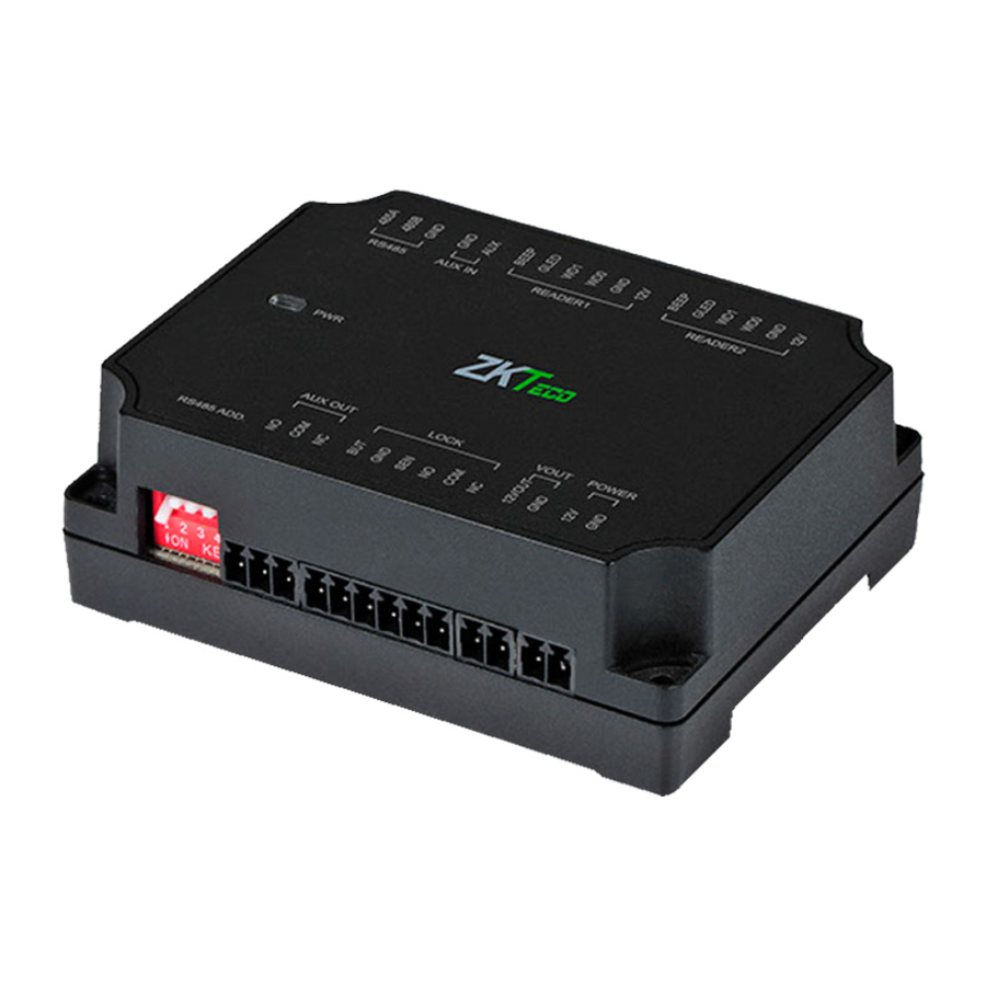
1. Appearance
Auxiliary input
EXT RS485
Wiegand reader
Indicator LED
Auxiliary
output
DIP switch
Version:1.0
Wiegand reader
12V output
Power
Lock
Date:2018.11
Status of indicator
Normal communication: the indicator
flash
es
every two seconds
Abnormal communication: the indicator
will be constant on.
The indicator flashes rapidly within 30s
after the device is connected to the power
supply.
address
switch setting
1
1 2 3 4
2
1 2 3 4
3
1 2 3 4
4
1 2 3 4
5
1 2 3 4
1
.
address
switch setting
6
1 2 3 4
7
1 2 3 4
8
1 2 3 4
9
1 2 3 4
10
1 2 3 4
Advertisement
Table of Contents

Related Manuals for ZKTeco DM10


Summary of Contents for ZKTeco DM10
- Page 1 D 10 Quick Start Guide Version:1.0 Date:2018.11 Appearance & Installation 1. Appearance Auxiliary input Wiegand reader Status of indicator Normal communication: the indicator EXT RS485 Wiegand reader flash every two seconds Abnormal communication: the indicator will be constant on. The indicator flashes rapidly within 30s after the device is connected to the power supply.
- Page 2 2 Installation Fix the guide rail on the wall 2 Install the device Wiring to Master Device The DM10 has to be connected to F18(master device) in order to use the software. 485+ 485A 485- 485B DC12V DC12V DC12V Router A access controller can connect eight DM10 at most.
- Page 3 Open ZKAccess3.5 software, click Device > New , input the name and IP address of F18 , and then click OK . Step 2 ...] [ Click More > Add IO Expansion Board , check RS485 address of DM10, and then click OK .
- Page 4 After successful configuration, the Indicator LED flashes every two 2 seconds, indicating communicate normally. After adding successfully, the parameters of the access control could be set, please refer to ZKAccess 3.5 user manual.
Need help?
Do you have a question about the DM10 and is the answer not in the manual?
Questions and answers