Table of Contents
Advertisement
Quick Links
Advertisement
Table of Contents

Related Manuals for Henny Penny CW-216


Summary of Contents for Henny Penny CW-216
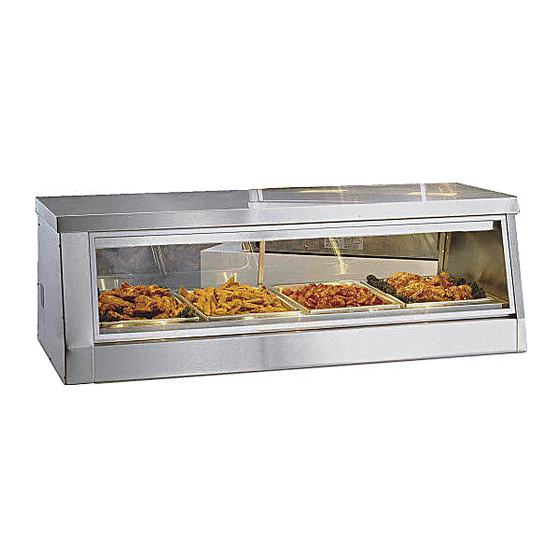
- Page 1 Henny Penny Display Counter Warmer Model CW-216/CW-114 TECHNICAL MANUAL...
-
Page 3: Table Of Contents
Model CW-216/CW-114 TABLE OF CONTENTS Section Page Section 1. TROUBLESHOOTING ....................1-1 1-1. Introduction ......................1-1 1-2. Safety ......................... 1-1 1-3. Troubleshooting ....................1-1 Section 2. MAINTENANCE ......................2-1 2-1. Introduction ......................2-1 2-2. Test Instruments ....................2-1 2-3. Light Bulb ......................2-1 2-4. -
Page 5: Section 1. Troubleshooting
Model CW-216/CW-114 SECTION 1. TROUBLESHOOTING 1-1. INTRODUCTION The section provides troubleshooting information in the form of an easy to read table. If a problem occurs during the first operation of a new cabinet, recheck the Installation Section of the Operator’s Manual. - Page 6 Model CW-216/CW-114 1-3. TROUBLESHOOTING (Continued) PROBLEM CAUSE CORRECTION THERMOMETER A. Reading does • Thermometer bulb is not in • Insert bulb in block not match holding block actual temperature • Replace per Thermometer Section • Faulty thermometer OPERATIONS A. Product not •...
- Page 7 Model CW-216/CW-114 1-3. TROUBLESHOOTING (Continued) PROBLEM CAUSE CORRECTION WATER SYSTEM A. Water will • Faulty float switch • Check float switch per Float Switch not fill Section • Faulty water control switch • Check water control switch per Water Control Switch Section •...
- Page 8 Model CW-216/CW-114 1-3. TROUBLESHOOTING (Continued) PROBLEM CAUSE CORRECTION HEATING SECTION A. Water will • Faulty contactor • Replace contactor per Contactor Section not heat • Faulty thermostat • Check thermostat per Thermostat Section • Faulty high limit switch • Check high limit switch per High Limit Switch Section B.
-
Page 9: Section 2. Maintenance
Model CW-216/CW-114 SECTION 2. MAINTENANCE 2-1. INTRODUCTION This section provides procedures for the checkout and replace- ment of the various parts used within the cabinet. Before replacing any parts, refer to the Troubleshooting Section. It will aid you in determining the cause of the malfunction. -
Page 10: Fuse
Model CW-216/CW-114 2-3. LIGHT BULB 3. Replace the light bulb with a Westinghouse (Continued) #60A19/35, 130 Volt bulb. If this bulb is not available, a standard 60 watt bulb will work until a long life bulb can be obtained. 4. Replace the glass panel. - Page 11 Model CW-216/CW-114 2-5. CLEANING WATER 3. Remove the control side end panel. STRAINER (Continued) 4. Remove the hex cap at the bottom of the water strainer. 5. Remove the screen from inside the strainer and clean. Step 4 6. Reassemble in reverse order.
-
Page 12: Water Strainer (Replacement)
Model CW-216/CW-114 2-6. WATER STRAINER 1. Remove electrical power supplied to the cabinet. (REPLACEMENT) To avoid electrical shock or property damage, move the power switch to OFF and disconnect main circuit breaker, or unplug cord at wall receptacle. 2. Shut off the water supply. - Page 13 Model CW-216/CW-114 2-7. WATER VALVE 4. Check across terminals of the water valve with an ohmmeter. (Continued) The meter reading should be 600-650, if reading is not correct replace the water valve by continuing with this procedure. 5. Remove the electrical wires from the water valve.
-
Page 14: Float Switch
Model CW-216/CW-114 2-8. FLOAT SWITCH 1. Remove electrical power supplied to the cabinet. To avoid electrical shock or property damage, move the power switch to OFF and disconnect main circuit breaker, or unplug cord at wall receptacle. 2. Drain the water pan by removing the drain standpipe. -
Page 15: Light Switch
Model CW-216/CW-114 2-9. LIGHT SWITCH 1. Remove electrical power supplied to the cabinet. To avoid electrical shock or property damage, move the power switch to OFF and disconnect main circuit breaker, or unplug cord at wall receptacle. 2. Remove control side and panel. -
Page 16: Water Control Switch
Model CW-216/CW-114 2-10. POWER SWITCH 4. Remove the nut from the control panel side of switch and (Continued) remove switch. 5. Install a new switch in reverse order. 6. Replace the end panel. 7. Turn on the power supply at the breaker box. -
Page 17: Infinite Switch
Model CW-216/CW-114 2-12. INFINITE SWITCH 1. Remove electrical power supplied to the cabinet. To avoid electrical shock or property damage, move the power switch to OFF and disconnect main circuit breaker, or unplug cord at wall receptacle. 2. Remove the control side end panel. -
Page 18: Indicating Light
Model CW-216/CW-114 2-13. THERMOSTAT 4. Remove the thermostat knob by loosening the set screw (Continued) and pulling it off. 5. Remove the sensor bulb by pulling on the capillary tube. 6. Remove the two mounting screws from the thermostat. 7. Install a new thermostat in reverse order. -
Page 19: Thermometer
Model CW-216/CW-114 2-14. INDICATING LIGHT 5. Install a new light by pushing the light through the control (Continued) panel until the light snaps securely in the panel. 6. Strip the wires and reconnect with wire nuts. 7. Replace the end panel. -
Page 20: Contactor
Model CW-216/CW-114 2-16. CONTACTOR 1. Remove electrical power supplied to the cabinet. To avoid electrical shock or property damage, move the power switch to OFF and disconnect main circuit breaker, or unplug cord at wall receptacle. 2. Remove the control side panel. -
Page 21: Water Pan Heater
Model CW-216/CW-114 2-18. WATER PAN HEATER 1. Remove electrical power supplied to the cabinet. To avoid electrical shock or property damage, move the power switch to OFF and disconnect main circuit breaker, or unplug cord at wall receptacle. 2. Remove the heater cover plates. -
Page 22: Light Socket
CW-114 (208 volts) ........ 43 ohms CW-114 (230 volts) ........ 53 ohms CW-216 lower (208 volts) ...... 43 ohms CW-216 lower (230 volts) ...... 53 ohms CW-216 upper (208 volts) ...... 108 ohms CW-216 upper (230 volts) ...... 132 ohms If a heater checks defective, replace it by continuing with this procedure. -
Page 23: High Limit Switch
Model CW-216/CW-114 2-21. HIGH LIMIT 1. Remove electrical power supplied to the cabinet. SWITCH To avoid electrical shock or property damage, move the power switch to OFF and disconnect main circuit breaker, or unplug cord at wall receptacle. 2. Remove control end panel. -
Page 24: Wiring Diagrams
Model CW-216/CW-114 2-22. WIRING DIAGRAMS 2-16... - Page 25 Model CW-216/CW-114 2-22. WIRING DIAGRAMS (Continued) 2-17...
- Page 26 Model CW-216/CW-114 2-22. WIRING DIAGRAMS (Continued) 2-18...
- Page 27 Model CW-216/CW-114 2-22. WIRING DIAGRAMS (Continued) 2-19...
- Page 28 Model CW-216/CW-114 2-22. WIRING DIAGRAMS (Continued) 2-20...
- Page 29 Model CW-216/CW-114 2-22. WIRING DIAGRAMS (Continued) 2-21...
- Page 30 Model CW-216/CW-114 2-22. WIRING DIAGRAMS (Continued) 2-22...
- Page 31 Model CW-216/CW-114 2-22. WIRING DIAGRAMS (Continued) 2-23...
- Page 32 Model CW-216/CW-114 2-24...
- Page 33 Model CW-216/CW-114 2-25...
- Page 34 Model CW-216/CW-114 2-26...
Need help?
Do you have a question about the CW-216 and is the answer not in the manual?
Questions and answers