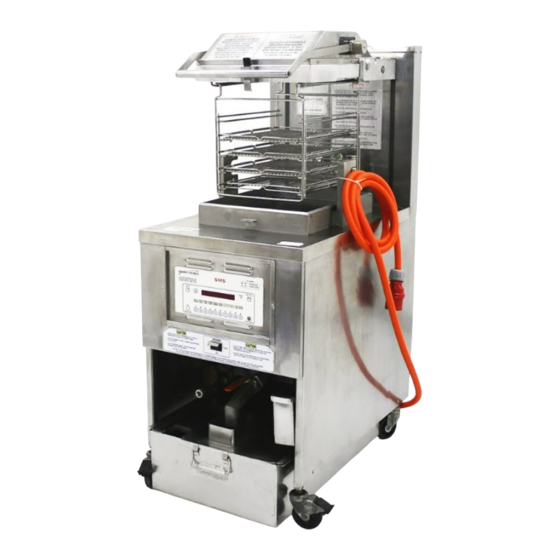
Advertisement
Quick Links
3-4.
CONTROLS AND
INDICATORS
2
1
10160009
9
Item
Name
1
SCAN Button
2
Temperature Button
3
Digital Display
4
HEAT Indicator
5
EXIT FILL Button
6
Menu Strip
7
EXIT COOL Button
8
Product Select Buttons
9
FUNTION Button
Oct 2016
3
8
Allows the operator to toggle through any running multiple
timers.
Allows the operator to read the temperature of the shortening
while in a Cook Cycle.
Display shows cooking times along with any prompts or
messages.
Illuminates whenever the control calls for heat; when short-
ening temperature is reached, the heat light goes off.
After filtering the fryer, if in the Filter Lockout Mode, the
display reads "FILL" and the EXIT FILL button must be
pressed.
Shows the name of the product associated with each product
button.
After cooking or filtering the fryer automatically goes into
cool mode (this keeps shorteneing at a lower temperature to
preserve shortenening life). The EXIT COOL button must be
pressed to heat the shortening to setpoint temperature.
Select the product to be cooked.
Used in the programming of the controls
23
Model 590/592
4
Description
5
6
7
Advertisement

Summary of Contents for Henny Penny 590
- Page 1 Model 590/592 3-4. CONTROLS AND INDICATORS 10160009 Item Name Description SCAN Button Allows the operator to toggle through any running multiple timers. Temperature Button Allows the operator to read the temperature of the shortening while in a Cook Cycle. Digital Display Display shows cooking times along with any prompts or messages.
-
Page 2: Number Keys
SMS 20 AUTO POLISH PROGRAMMING INSTRUCTIONS POWER PU M P ENABLING THE POLISH FUNCTION KEYS 1. Press and hold the FUNCTION key until “REG PROGRM” appears. 2. Release the key for a second and then at approximately 1 second intervals press and release the FUNCTION key until “PLSH ENABL”... - Page 3 SMS 20 AUTO POLISH PROGRAMMING INSTRUCTIONS POWER PU M P CHANGING AM/PM TIME OF DAY 1. Depressing any of the number keys will toggle the AM indicator to PM (and then back again to AM). 2. When the correct option is selected, press and release the FUNCTION key to set the 12 hour mode option.
- Page 4 SMS 20 AUTO POLISH PROGRAMMING INSTRUCTIONS POWER PU M P CHANGING THE YEAR 1. Use the number keys to enter the correct year setting. 2. After the year is set, press and release the FUNCTION key to save the year setting. The display will show “XX:YY P1”...
- Page 5 SMS 20 AUTO POLISH PROGRAMMING INSTRUCTIONS POWER PU M P CHANGING THE EVENT POLISH TIME 1. Use the number keys to change the length of the event polish time in minutes. Valid entries are 0 (for no event) to 60 minutes. 2.
- Page 6 SMS 20 AUTO POLISH PROGRAMMING INSTRUCTIONS POWER PU M P POLISH TEMPERATURE PROGRAMMING 1. Use the number keys to enter the desired temperature at which the controller will regulate (thermostatically) during the polish program. The default temperature is 300° F. 2.
- Page 7 SMS 20 AUTO POLISH PROGRAMMING INSTRUCTIONS POWER PU M P ENABLING DAYLIGHT SAVINGS Depressing any of the number keys will toggle the daylight savings option from “OFF” to “ON” (and from “ON” to “OFF”). If you are located in a part of the country which uses daylight savings time, turn this option ON, otherwise leave it OFF.
-
Page 8: Section 4. Sms Programming
Model 690 SECTION 4. SMS PROGRAMMING Programming information is provided in this section. Operator menus are described in the Operator’s manual and are not included in this manual. All menus that pertain to maintenance are described in this section. To enter the menus perform the following steps: 1. - Page 9 Model 690 Table: 4-2 Tech I/O Menu (access code 246) Option Parameters/Functions Inputs Looks at the condition of the pump either On or Off. User Calibration Calibrates the temperature probe inside of the vat. RTD Test Shows offset of temperature probe when Product button 1 is pressed.
- Page 10 Model 690 Option Parameters/Functions Cool Proportional Temperature below cool set temp at which proportional control Bandwidth takes over. Example - if set to 15, at 15 degrees below cool set point, control starts pulsing the heat. Up to that point heat is ther- mostatically controlled.
- Page 11 Model 500/561/600 The SMS control has been replaced by the SMS 20 control. The SMS control is no longer orderable. The SMS kits have been updated to include to the SMS-20. The kit numbers are the same execpt the SMS has been replaced by the SMS-20 and any additional hardware needed to install the SMS-20. Refer to the tables below when ordering a replacement SMS20 control. 10160012 Figure 3-36.
- Page 12 ITEM NO. NUMBER DESCRIPTION PER ASSY PFE-500 KFC SMS-20 CONTROLS & SPARE PARTS 3-36 97924 SMS-20 Control, PFE-500 .............. 92495 CARD, Menu 580/590/690 ............. 97984 CARD, Menu KFC 600 SMS-20 ............. 97501 DECAL, KFC 600 SMS 20 ............. 51877 SPEAKER, w/wire ................14789 KIT, SMS-20 Conversion Dom. (SN: KA020JJ & Below) (Units with wiring diagram 24853, 24718 or 63211) .........
- Page 13 UNITS ITEM NO. NUMBER DESCRIPTION PER ASSY PFG-600 KFC SMS-20 CONTROLS & SPARE PARTS 3-36 97925 SMS-20 Control, PFE-600 ..............92495 CARD, Menu 580/590/690 ..............97984 CARD, Menu KFC 600 SMS-20 ............97501 DECAL, KFC 600 SMS 20 ..............51877 SPEAKER, w/wire................14807 KIT, SMS-20 Conversion Dom. (SN: KA020JJ & Below) ....14811 KIT, SMS-20 Conversion Dom.
- Page 14 Errors 4, 5, 6, 41, 46, and 71. 600 (96824): Errors 4, 5, 6, 41, 46, and 71. JAPAN 580,590 (97412): Errors 4, 5, 6, 16, 41, 46, and 71. JAPAN 390,690 (97413): Errors 4, 5, 6, 16, 32, 41, 46, and 71.


Need help?
Do you have a question about the 590 and is the answer not in the manual?
Questions and answers