Compaq Armada 7800 Reference Manual
Hide thumbs
Also See for Armada 7800:
- White paper (19 pages) ,
- Quickspecs (13 pages) ,
- Frequently asked questions manual (26 pages)
Table of Contents
Advertisement
Notice
The information in this guide is subject to change without notice.
COMPAQ COMPUTER CORPORATION SHALL NOT BE LIABLE FOR
TECHNICAL OR EDITORIAL ERRORS OR OMISSIONS CONTAINED
HEREIN; NOR FOR INCIDENTAL OR CONSEQUENTIAL DAMAGES
RESULTING FROM THE FURNISHING, PERFORMANCE, OR USE OF
THIS MATERIAL.
This guide contains information protected by copyright. No part of this
guide may be photocopied or reproduced in any form without prior
written consent from Compaq Computer Corporation.
© 1998 Compaq Computer Corporation.
All rights reserved. Printed in U.S.A.
Compaq, Armada, and LTE are registered in the U.S. Patent and
Trademark Office.
Microsoft, MS-DOS, and Windows are registered trademarks of
Microsoft Corporation.
The software described in this guide is furnished under a license
agreement or nondisclosure agreement. The software may be used or
copied only in accordance with the terms of the agreement.
Product names mentioned herein may be trademarks and/or registered
trademarks of their respective companies.
R
G
EFERENCE
UIDE
Armada 7800 Family of Personal Computers
First Edition, March 1998
Part Number 314932-001
Compaq Computer Corporation
Advertisement
Table of Contents

Related Manuals for Compaq Armada 7800


Summary of Contents for Compaq Armada 7800
- Page 1 Compaq Computer Corporation. © 1998 Compaq Computer Corporation. All rights reserved. Printed in U.S.A. Compaq, Armada, and LTE are registered in the U.S. Patent and Trademark Office. Microsoft, MS-DOS, and Windows are registered trademarks of Microsoft Corporation.
-
Page 2: Table Of Contents
Setting Up the Software ..............1-9 Operating the Computer During Setup........1-9 Choosing a Language..............1-9 Removing the Operating System ..........1-10 Restoring Your Operating System and Software Preinstalled by Compaq .................1-10 Completing Setup................1-11 Registering the Computer ............1-11 Locating Online Resources............1-11 chapter 2 AKING A... - Page 3 chapter 3 SING THE EYBOARD AND OINTING EVICE Using the Pointing Device ............... 3-1 Keyboard Components ..............3-3 Hotkey Quick Reference..............3-4 Moving the Hotkey Popup Window Location ......3-5 Switching Displays..............3-6 Adjusting System Warning Beep Volume ........3-7 Initiating QuickLock/QuickBlank..........
- Page 4 Hibernation Overview ..............4-8 Initiating Hibernation..............4-9 Enabling/Disabling Hibernation ..........4-10 Exiting Hibernation..............4-10 Timeout Overview................4-11 Setting the Screen Save Timeout..........4-11 AC Energy Saver Overview............4-12 Enabling/Disabling PC Card Slots..........4-12 chapter 5 SING ATTERY ACKS Battery Components.................5-1 Using a New Battery Pack ...............5-2 Charging Battery Packs..............5-2 Charging Battery Packs in the Computer ........5-2 Charging Battery Packs Outside of Normal Operating Conditions..............5-3...
- Page 5 chapter 6 ORKING WITH EMOVABLE RIVES Removable Drive Bays ..............6-1 Caring for Removable Drives ............6-2 MultiBay Weight Saver ..............6-3 Hard Drives ..................6-4 Removing a Hard Drive from the Hard Drive Bay ..... 6-4 Inserting a Hard Drive into the Hard Drive Bay ......6-6 Removing a Hard Drive from the MultiBay .......
- Page 6 Using Online Mode ................7-10 Escaping from an Online Session to the Command Mode..7-10 Creating a Command Mode Shortcut ........7-11 Creating a Command Mode Icon..........7-12 Using the Modem with a Cellular Phone (United States Only)..7-13 Choosing Cellular Direct Components........7-13 Connecting the Modem to a Cellular Phone......7-14 Registering the Phone with the Modem ........7-15 Using PIN Dialing ..............7-16 PIN Dialing When Using a Stored Dial Suffix ......7-16...
- Page 7 chapter 10 SING UDIO EATURES Introducing the Audio Components ..........10-1 Using Internal and External Microphones........10-2 Using Internal and External Speakers ........... 10-4 Internal Speakers ............... 10-4 External Speakers ..............10-4 Identifying Audio Connections ............. 10-6 Controlling Audio Volume ............10-8 chapter 11 RAM M PGRADING...
- Page 8 Setup Password ................13-6 Setting the Setup Password............13-6 Entering the Setup Password .............13-7 Changing the Setup Password ...........13-7 Deleting the Setup Password .............13-8 Change/Delete Password Symbols..........13-9 Using the Quick Controls.............13-10 Enabling and Disabling QuickLock/QuickBlank } Using Windows 95..............13-10 Enabling and Disabling QuickLock/QuickBlank Using Windows NT ..............13-11 DriveLock Overview..............13-11 User and Master Passwords Overview ........13-12...
- Page 9 Using Compaq Utilities ..............15-3 Running Computer Checkup (TEST)........15-4 Running View System Information (INSPECT) ...... 15-5 Running Compaq Diagnostics........... 15-5 Boot Sequencing ................15-6 Factory Default Settings ..............15-7 chapter 16 ROUBLESHOOTING Checklist for Solving Problems ............. 16-1 Solving Audio Problems..............16-2 Computer does not beep after the Power-On Self-Test (POST) ...............
- Page 10 Solving Infrared Problems ............16-16 Cannot communicate with another computer......16-16 Cannot transmit data ..............16-17 Infrared port does not work .............16-19 Solving Keyboard/Numeric Keypad Problems......16-20 Screen is blank and keyboard is working ........16-20 Embedded numeric keypad on computer keyboard is disabled.................16-20 Solving PC Card Problems............16-21 Computer does not beep when a PC Card is inserted....16-21 Computer beeps only once when a PC Card is inserted..16-22 PC Card drivers fail with error messages during...
- Page 11 Solving Modem Problems ............16-32 Modem loses connection ............16-32 Characters are garbled/transfer rates are slow......16-32 Phone line noise causes a disconnection......... 16-33 No dial tone ................16-33 Cellular connection doesn’t work (United States only)..16-34 Ten digit dialing does not work correctly under Windows 95................
- Page 12 preface SING UIDE Some or all of the following format conventions are used in this guide to distinguish elements of text: Names of keys are shown in bold type as they appear on the keyboard, for example, Ctrl, Backspace, Tab. Keys that you should press at the same time are represented by the key names and the plus (+) symbol, for example, Ctrl+Alt+Delete.
-
Page 13: Getting Started
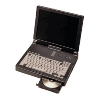
chapter ETTING TARTED Unpacking the Computer You should have the following items in the packing box: 1 Computer 2 Diskette drive 3 MultiBay weight saver 4 Hard drive 5 Lithium ion battery pack 6 CD-ROM drive 7 Hard drive carrying case 8 Power cord 9 Modem cable : MultiBay device carrying case... - Page 14 Items not illustrated vary by model and geographical region: Owner Registration Card Warranty and service information Printed documentation about the computer 1-2 Getting Started...
-
Page 15: Taking The Battery Pack Out Of Ship Mode
Taking the Battery Pack Out of Ship Mode Before you set up the computer, you must take the battery pack out of ship mode so that it can be charged. Take the battery pack out of ship mode by removing and reinserting the battery pack: 1 Tilt the computer 1 to access the battery release latch. - Page 16 3 Pull the battery pack out of the battery bay. 4 Remove the sticker from the battery pack. 5 Reinsert the battery pack into the battery bay until it clicks into place. NOTE: Ship mode does not apply to traveling with or shipping the computer.
-
Page 17: Setting Up The Computer
Although a new battery pack can be used to power the computer after receiving a partial charge, Compaq recommends that a new battery pack be allowed to fully charge before the computer is disconnected from external power or before the battery pack is removed from the computer. -
Page 18: Connecting The Power Cord
Connecting the Power Cord 1 Place the computer on a flat surface near an electrical outlet. 2 Plug the power cord into the power connector on the rear panel of the computer 1, then into the electrical outlet 2. NOTE: In Japan, you must first plug the power cord into the 3-to-2- prong plug adapter included with the computer. -
Page 19: Opening The Computer
Opening the Computer Slide forward the display release latch 1 on the front of the display, then raise the display 2 to a comfortable viewing angle. Adjusting the Keyboard To elevate the back of the keyboard, swivel the tilt feet back and down. -
Page 20: Turning On The Computer
Turning On the Computer Slide the power switch and release it. Whenever the computer is turned on, the power/suspend light turns on to indicate that power is turned on. NOTE: To restore the screen if it is cleared by the screen saver during a period of keyboard and mouse inactivity, press the Shift key. -
Page 21: Setting Up The Software
Setting Up the Software When you begin software setup, online instructions guide you through the setup process. IMPORTANT: After you begin software setup, you must complete the entire process, which may require up to 20 minutes. Make sure the computer is plugged in for this process to ensure that software setup is uninterrupted. -
Page 22: Removing The Operating System
If it is necessary to reinstall the operating system and you do not want to lose these enhancements, it will also be necessary to reinstall all Compaq software for your computer. Contact Compaq customer support for more information on this additional software and the various tools available to help reinstall. -
Page 23: Completing Setup
Click Start Æ Compaq Information Center Æ Reference Guide Click Start Æ Help Æ Contents Æ Reference Guide To access the Options Catalog online: Click Start Æ Compaq Information Center Æ Options Catalog To access information on the Internet, go to www.compaq.com. Getting Started 1-11... -
Page 25: Aking A
chapter AKING A OOK AT THE OMPUTER Front Components Front Components Component Function Mono microphone Built-in monophonic microphone for the multimedia sound system. Stereo speakers Built-in speakers for computer sounds and the multimedia sound system. Continued Taking a Look at the Computer 2-1... - Page 26 Front Components Continued Component Function MultiBay A multifunction device compartment in the computer base that supports a removable hard drive, diskette drive, or CD- ROM drive, or an extra battery pack. Hard drive bay Holds the removable hard drive shipped with the computer. Battery bay Holds the main battery pack in the computer.
-
Page 27: Left Side Components
Left Side Components Left Side Components Component Function Airflow exhaust used to keep the internal components of the computer cool. The fan will automatically run when needed. Battery bay Holds the main battery pack in the computer. Taking a Look at the Computer 2-3... -
Page 28: Rear Components
Rear Components Rear Components Component Function USB connector Connects a Universal Serial Bus (USB) device or a hub that connects multiple USB devices.* Mono microphone jack Connects an external monophonic microphone. Stereo speaker/headphone Connects stereo headphones or jack external stereo speakers to the computer. - Page 29 Rear Components Continued Component Function External monitor connector Connects an optional external display, such as an external CRT monitor. Also connects a TV adapter, allowing a TV to be connected to the computer. Keyboard/mouse connector Connects an optional full-sized keyboard or a PS/2 compatible mouse.
-
Page 30: Right Side Components
Right Side Components Right Side Components Component Function Security slot A slot for an optional cable lock to secure the computer to a fixed object. PC Card eject levers Located on the right side of the computer and used to release the PC Cards from the PC Card slots. -
Page 31: Top Components
Top Components Top Components Component Function Display switch Turns off the display if the display is closed while the computer is still on. If warning beeps are enabled in Computer Setup, a beep will sound if the display is closed when the computer is on. - Page 32 Top Components Continued Component Function Volume control Controls volume to the built-in speakers or to external speakers or headphones plugged into the stereo speaker/headphone jack on the computer. Power switch Turns the computer on or off, or exits Suspend. When the computer is in Suspend, sliding the power switch exits Suspend but does not turn off the computer.
-
Page 33: Bottom Components
Bottom Components Bottom Components Component Function Battery release latch Releases the battery pack from the battery bay. Hard drive release latch Releases the hard drive from the hard drive bay. Docking restraint latch recess Helps to secure the computer to the desktop expansion base. -
Page 34: Display Controls
Display Controls Display Controls Component Function Display release latch Slides to the right to open the computer. Display switch Turns off the display if the display is closed while the computer is still on. If warning beeps are enabled in Computer Setup, a beep sounds if the display is closed when the computer is on. -
Page 35: Mpeg Overview
MPEG Overview MPEG (Moving Pictures Experts Group) refers to a type of data compression optimized for video and audio data. By analyzing the changes between frames (differencing), an MPEG encoder is able to reduce the file size of the data by a ratio of up to 200 to 1. This compression method provides true full-screen and full-motion video and CD quality audio to be stored in a relatively small sized file. -
Page 36: Ordering Preinstalled Software
Compaq worldwide telephone numbers in Appendix A, “Compaq Customer Support.” Have the computer serial number available when you IMPORTANT: call Compaq. The serial number is on the bottom of the computer. 2-12 Taking a Look at the Computer... -
Page 37: Using The Keyboard And Pointing Device
chapter SING THE EYBOARD AND OINTING EVICE Using the Pointing Device Using the Keyboard and Pointing Device 3-1... - Page 38 Pointing Device Components Component Function EasyPoint III pointing device Provides mouse functions in all software that supports a Microsoft- compatible mouse. Left mouse button Initiates an action or confirms a selection. Right mouse button Initiates an action or confirms a selection.
-
Page 39: Keyboard Components
Keyboard Components 1 Function keys (F1-F12) 2 Screen control keys 3 Embedded numeric keypad 4 Enter key 5 Cursor keys 6 Alt keys 7 Ctrl keys 8 Fn key 9 Shift key : Caps Lock key ; Tab key < Esc key Using the Keyboard and Pointing Device 3-3... -
Page 40: Hotkey Quick Reference
Hotkey Quick Reference Hotkeys are keys that simplify performing special computer operations. The special hotkey features are activated by pressing the Fn key and the function key. The function keys work as normally defined by application software when they are not used in conjunction with the Fn key. -
Page 41: Moving The Hotkey Popup Window Location
Moving the Hotkey Popup Window Location Press the Fn+F1 hotkeys to move the popup window location. Press the up and down arrow keys to move the icon up or down. Press the left and right arrow keys to move the icon left or right. -
Page 42: Switching Displays
Switching Displays Press the Fn+F4 hotkeys to display information on the computer display, external monitor, or TV screen. Pressing these hotkeys toggles between several display modes, depending on the equipment connected to the computer. All scenarios assume you are starting from the computer display enabled. -
Page 43: Adjusting System Warning Beep Volume
Adjusting System Warning Beep Volume Press the Fn+F5 hotkeys to adjust the system warning beep volume. To increase volume, press the right arrow key. To decrease volume, press the left arrow key. (The arrows in this illustration indicate the increase or decrease in volume levels.) Using the Keyboard and Pointing Device 3-7... -
Page 44: Initiating Quicklock/Quickblank
Initiating QuickLock/QuickBlank Before QuickLock/QuickBlank can be initiated, a IMPORTANT: power-on password must be set and QuickLock/QuickBlank must be enabled. Press the Fn+F6 hotkeys to initiate QuickLock/QuickBlank at any time and from within any application. This hotkey Disables the keyboard and the pointing device. Clears the display. -
Page 45: Selecting A Power Management Level
Selecting a Power Management Level Use the Fn+7 hotkeys to Select one of the three preset power conservation levels. Customize the power conservation level. Press the Fn+F7 hotkeys to view or change the Power Management level. Press the left or right arrow keys to select a different level. The power conservation level assists you in extending the life of the battery pack(s). -
Page 46: Accessing The Battery Gauge
Accessing the Battery Gauge Press the Fn+F8 hotkeys to show the status of the battery pack(s). Four numbered boxes indicate the status of each installed battery pack: Battery pack 1—Primary battery in the computer battery bay. Battery pack 2—Battery in the computer MultiBay. Battery pack 3—Battery in the expansion base MultiBay or the convenience base battery charging bay. -
Page 47: Adjusting The Brightness Control
Adjusting the Brightness Control Press the Fn+F10 hotkeys to adjust the display brightness: Press the right arrow key to increase light intensity. Press the left arrow key to decrease light intensity. Using the Keyboard and Pointing Device 3-11... -
Page 48: Accessing The Bios Version Number
Accessing the BIOS Version Number Press the Fn+Esc hotkeys to find out what version of BIOS you are running. BIOS stands for “Basic Input/Output System” and is a ROM- resident software that provides basic functionality for the computer. Press the up and down arrow keys to display other software version numbers. -
Page 49: Accessing The Embedded Numeric Keypad
Accessing the Embedded Numeric Keypad The embedded numeric keypad is a section of the computer keyboard that converts to a numeric keypad when the number lock function is enabled. The embedded numeric keypad is disabled if an external NOTE: keyboard or keypad is attached. Press the Fn+Num Lk hotkeys to Enable the embedded numeric keypad. -
Page 50: Stretching Text
Stretching Text To stretch the image so that more of the screen is filled, press the Fn+T hotkeys. The Fn+T function is available whenever the desktop area resolution is set lower than the resolution of the internal display device (LCD). When running MS-DOS under Windows (text mode), toggle the Fn+T hotkeys to switch between stretched text mode and regular mode. -
Page 51: Programmable Keys Overview
Programmable Keys Overview 1 First Programmable Key 2 Second Programmable Key 3 Third Programmable Key 4 Fourth Programmable Key Programmable Keys allow you to assign functions such as opening an application or bringing up a document. You can assign the programmable keys to quickly open an application on your computer, bring up a document, or emulate one of the Microsoft Windows and Application Logo keys. -
Page 52: Assigning Or Reassigning Programmable Keys
Assigning or Reassigning Programmable Keys 1 Access the Programmable Keys utility. 2 Select the programmable key you wish to assign or reassign for the current scheme by clicking its radio button in the Key assignments box. To assign keys in other than the current scheme, click NOTE: Show Advanced Options and look in the Scheme box to choose another scheme. -
Page 53: Unassigning Programmable Keys
Unassigning Programmable Keys 1 Access the Programmable Keys utility. 2 Select the programmable key you wish to unassign and click the corresponding button in the Key assignments group box. : To unassign keys in other than the current scheme, NOTE click Show Advanced Options and select a different scheme. -
Page 54: Removing Schemes
Removing Schemes 1 Access the Programmable Keys utility. 2 Place a check in the Show advanced options checkbox if one is not already there. 3 Select the scheme you want to remove from the drop-down list. The Default scheme is not removable. NOTE: Click the Remove button. -
Page 55: Using Power And Power Management
chapter SING OWER AND OWER ANAGEMENT Leaving On the Computer When you need to leave the computer unattended but don’t want to turn if off, you can conserve power by initiating Suspend. Always initiate Suspend when a battery pack is your only power source. -
Page 56: Power Management Overview
Power Management Overview The computer comes standard with a collection of power management features that allow you to extend battery operating time and conserve power. Power management monitors most of the computer components such as the hard drive, processor, and display. When a component is inactive for a specified period of time, called a timeout, you can use power management settings to shut it down temporarily. -
Page 57: Setting The Power Management Level
Setting the Power Management Level Power Management Levels To extend the life of your battery packs, use the Battery Conservation tab in Power Properties. You can customize the level of battery conservation or use one of four power management levels: High—Select this level for the maximum amount of power conservation possible in an automatic setting. -
Page 58: Setting The Power Management Level With Power Properties
Setting the Power Management Level With Power Properties Change the default levels of battery conservation through the Conservation Settings tab in Power Properties. Choose a preset level or customize your own. The level you set remains in effect until you change it. Setting the Power Management Level With Computer Setup If you are experiencing difficulty accessing Power Properties through Windows, you may set Power Management using... -
Page 59: Suspend Overview
Suspend Overview Suspend is a condition in which the computer uses a low amount of power by shutting down most of the subsystems. Suspend can be user-initiated or system-initiated (if a Suspend timeout has been set). When you initiate Suspend, system information is saved in random access memory (RAM). - Page 60 System-initiated Suspend Initiates after five minutes (default) or a user-selected timeout during normal battery operations. Initiates when the system reaches a critical low battery condition and Hibernation has been disabled. CAUTION: If Hibernation is disabled, the computer does not initiate Hibernation when a critical low battery condition is reached.
-
Page 61: Exiting Suspend
Exiting Suspend If Suspend was initiated because the timeout expired, press the suspend button 1 or slide the power switch 2. If Suspend was initiated because the system reached a critical low battery condition while Hibernation was disabled, exit in one of these ways: Connect the power cord or the Automobile Adapter or dock the computer in the optional desktop expansion base or... -
Page 62: Hibernation Overview
Conserve battery power—Conserve battery power by customizing the Hibernation timeout to save information in memory after a specified period of inactivity. CAUTION: It is possible to remove Compaq Power Management from the computer using Add/Remove Programs. Compaq strongly recommends against doing so, however. Removing... -
Page 63: Initiating Hibernation
Initiating Hibernation User-initiated Hibernation Press Fn and the suspend button simultaneously at any time and from anywhere within an application. : Hibernation cannot be initiated when the computer is NOTE docked in the desktop expansion base or convenience base. System-initiated Hibernation Initiates when the computer is on but idle, left unattended, and reaches critical low battery condition. -
Page 64: Enabling/Disabling Hibernation
Enabling/Disabling Hibernation Hibernation is automatically turned on when you first set up the computer. In order for Hibernation to work, it must allocate space on the hard drive equal to the amount of RAM installed. You can disable Hibernation to free up disk space. However, disabling it is not recommended. -
Page 65: Timeout Overview
Timeout Overview A timeout is a specified period of inactivity for the computer or its components. After this time period passes, power management shuts down the computer or its components to save battery power. For example, the hard drive component default timeout is two minutes. -
Page 66: Ac Energy Saver Overview
AC Energy Saver Overview When the computer is connected to AC power, the AC Energy Saver shuts down the hard drive and initiates the screen saver after set timeouts expire. Enabling/Disabling PC Card Slots PC Cards are small form factor options that require power when inserted in the computer. -
Page 67: Using Battery Packs
chapter SING ATTERY ACKS Battery Components The quick check feature on the lithium-ion (Li-ion) battery pack shows the remaining charge level when the battery pack is outside of the battery bay or MultiBay. To see the remaining power in the battery pack, press the battery gauge 1. -
Page 68: Using A New Battery Pack
Using a New Battery Pack A new battery pack should be charged fully before it is used for the first time. The battery pack will work without being fully charged, but the battery gauge will not show an accurate charge until the battery pack receives its first full charge. -
Page 69: Charging Battery Packs Outside Of Normal Operating Conditions
Charging Battery Packs Outside of Normal Operating Conditions Under normal operating conditions, charging a battery pack begins when the computer is connected to a power source (Automobile Adapter, power cord, optional desktop expansion base, or optional convenience base). Although the battery power light may turn on, charging may not occur immediately if one of the following conditions exists: The battery pack temperature is outside the normal operating... -
Page 70: Identifying A Low Battery Condition
Identifying a Low Battery Condition The computer beeps every 15 seconds and the battery power light blinks to indicate a low battery condition. Beeps can be turned off using Computer Setup. NOTE: CAUTION: When you are alerted to a low battery condition, very little battery charge remains. -
Page 71: Resolving A Low Battery Condition
Resolving a Low Battery Condition Resolving a Low Battery Condition by Connecting to an Electrical Outlet To charge battery packs in the computer while connected to an electrical outlet: 1 Connect the power cord to the power connector on the rear panel of the computer. -
Page 72: Resolving A Low Battery Condition By Connecting To The Automobile Adapter
Resolving a Low Battery Condition by Connecting to the Automobile Adapter 1 Connect the pronged end of the power cord into the Automobile Adapter 1. 2 Connect the power cord to the rear of the computer 2. 5-6 Using Battery Packs... - Page 73 Insert the large end of the Automobile Adapter cable into the cigarette lighter. Leaving the computer connected to the vehicle with IMPORTANT: the Automobile Adapter for an extended period of time when the vehicle is off may deplete the vehicle battery. Depletion occurs regardless of whether the computer is turned on or off.
-
Page 74: Resolving A Low Battery Condition By Replacing The Battery Pack
Resolving a Low Battery Condition by Replacing the Battery Pack CAUTION: If you are removing the battery pack while the computer is on, you can prevent loss of information by initiating Suspend before removing the battery pack. Be sure to replace the discharged battery pack with a charged one within 10 minutes. -
Page 75: Replacing Battery Packs
Replacing Battery Packs Removing the Battery Pack from the Battery Bay CAUTION: If you are removing the battery pack while the computer is on, you can prevent loss of information by initiating Suspend before removing the battery pack. Be sure to replace the discharged battery pack with a charged one within 10 minutes 1 Save your data. - Page 76 4 Remove the battery pack. 5-10 Using Battery Packs...
-
Page 77: Inserting The Battery Pack In The Battery Bay
Inserting the Battery Pack in the Battery Bay CAUTION: If you are removing the battery pack while the computer is on, you can prevent loss of information by initiating Suspend before removing the battery pack. Be sure to replace the discharged battery pack with a charged one within 10 minutes. -
Page 78: Removing The Battery Pack From The Multibay
Removing the Battery Pack from the MultiBay CAUTION: If you are removing the battery pack while the computer is on, you can prevent loss of information by initiating Suspend before removing the battery pack. Be sure to replace the discharged battery pack with a charged one within 10 minutes. - Page 79 3 Remove the battery pack. Using Battery Packs 5-13...
-
Page 80: Inserting The Battery Pack In The Multibay
Inserting the Battery Pack in the MultiBay CAUTION: If you are removing the battery pack while the computer is on, you can prevent loss of information by initiating Suspend before removing the battery pack. Be sure to replace the discharged battery pack with a charged one within 10 minutes. -
Page 81: Storing Battery Packs
Storing Battery Packs When storing the computer for more than two weeks, remove the battery packs and store them separately to reduce the discharge rate and increase battery life. Battery packs self-discharge even when they are not being used. The rate of self-discharge is affected by temperature. To prolong battery charge, store them in a cool, dry place. -
Page 82: Maximizing Battery Pack Life
Maximizing Battery Pack Life Battery pack operating time varies depending on the system components, options, and applications being used. You can increase battery operating time by as much as 50 percent by controlling the energy required by the computer and the energy stored in the battery pack. -
Page 83: Beeps When Display Is Closed And Computer Is Turned On
To find out if the battery pack recycling program is available in your geographical location, check the worldwide telephone numbers in Appendix A. If a number for recycling is not listed for your area, contact your Compaq authorized dealer, reseller, or service provider. Using Battery Packs 5-17... -
Page 85: Working With Removable Drives
chapter ORKING WITH EMOVABLE RIVES Removable Drive Bays The computer has two bays for removable drives: A hard drive bay that supports only the primary hard drive. A MultiBay that supports a diskette drive, CD-ROM drive, secondary hard drive, or second battery pack. The optional desktop expansion base has two bays: A MultiBay that supports a diskette drive, CD-ROM drive, second hard drive, or second battery pack. -
Page 86: Caring For Removable Drives
Caring for Removable Drives Removable drives (hard drive, CD-ROM drive, diskette drive) are fragile computer components that must be handled with care. CAUTION: To prevent damage to the computer or removable drive or loss of information, observe the following precautions. Back up the information on a hard drive before removing it. -
Page 87: Multibay Weight Saver
After removing a hard drive, place it into the hard drive carrying case. After removing a CD-ROM drive or diskette drive, place it into the MultiBay device carrying case. Do not use the MultiBay device carrying case to store or transport a hard drive. -
Page 88: Hard Drives
Hard Drives Removing a Hard Drive from the Hard Drive Bay CAUTION: To prevent damage to the computer and hard drive, and loss of information, turn off the computer before removing the hard drive from the hard drive bay. Do not remove the hard drive while the computer is turned on, in Suspend, or in Hibernation. - Page 89 3 Remove the hard drive. 4 Grasp the drive by the metal edges and pull it out of the hard drive carrier. 5 Put the hard drive into the hard drive carrying case. Working with Removable Drives 6-5...
-
Page 90: Inserting A Hard Drive Into The Hard Drive Bay
Inserting a Hard Drive into the Hard Drive Bay CAUTION: To prevent damage to the computer and hard drive, and loss of information, turn off the computer before inserting the hard drive into the hard drive bay. Do not insert the hard drive while the computer is turned on, in Suspend, or in Hibernation. -
Page 91: Removing A Hard Drive From The Multibay
Removing a Hard Drive from the MultiBay CAUTION: To prevent damage to the computer and hard drive and loss of information, turn off the computer before removing a hard drive from the MultiBay. Do not remove the hard drive while the computer is turned on, in Suspend, or in Hibernation. - Page 92 3 Remove the Hard Drive MultiBay Adapter. 4 Remove the hard drive from the Hard Drive MultiBay Adapter. 5 Put the hard drive into the hard drive carrying case. 6-8 Working with Removable Drives...
-
Page 93: Inserting A Hard Drive Into The Multibay
Inserting a Hard Drive into the MultiBay CAUTION: To prevent damage to the computer and hard drive and loss of information, turn off the computer before inserting a hard drive into the MultiBay. Do not insert the hard drive while the computer is turned on, in Suspend, or in Hibernation. -
Page 94: Cd-Rom Drives
CD-ROM Drives Removing a CD-ROM Drive from the MultiBay CAUTION: To prevent damage to the computer and CD-ROM drive and loss of information, turn off the computer before removing a CD- ROM drive from the MultiBay. Do not remove the CD-ROM drive while the computer is turned on, in Suspend, or in Hibernation. - Page 95 5 Pull out the CD-ROM drive and put it in the MultiBay device carrying case. Working with Removable Drives 6-11...
-
Page 96: Inserting A Cd-Rom Drive Into The Multibay
Inserting a CD-ROM Drive into the MultiBay CAUTION: To prevent damage to the computer and CD-ROM drive and loss of information, turn off the computer before inserting a CD- ROM drive into the MultiBay. Do not insert the CD-ROM drive while the computer is turned on, in Suspend, or in Hibernation. -
Page 97: Working With Compact Discs
Working with Compact Discs Inserting a Compact Disc into the CD-ROM Drive 1 Turn on the computer. 2 Press the eject button on the bezel of the CD-ROM drive to release the CD loading tray. 3 Slowly pull out the CD loading tray until it is fully extended. 4 Remove the CD from its protective case and place it in the CD loading tray, label side up. - Page 98 5 Push lightly on the bezel of the CD loading tray to close it. The light on the CD-ROM drive turns on while the CD is checked and the Table of Contents is being read. The light turns off when the CD-ROM drive is ready to receive commands.
- Page 99 Removing a Compact Disc from the CD-ROM Drive 1 Turn on the computer. 2 Press the eject button on the front panel to open the CD loading tray. 3 Slowly pull out the CD loading tray until it is fully extended. Working with Removable Drives 6-15...
- Page 100 4 Remove the CD from the tray. Handle the CD by the edges, not by the flat surfaces. 5 Place the CD in its protective case. 6 Push the front panel of the CD loading tray to close it. 6-16 Working with Removable Drives...
-
Page 101: Diskette Drives
Diskette Drives Removing a Diskette Drive from the MultiBay CAUTION: To prevent damage to the computer and diskette drive and loss of information, turn off the computer before removing a diskette drive from the MultiBay. Do not remove the diskette drive while the computer is turned on, in Suspend, or in Hibernation. - Page 102 4 Pull out the diskette drive. 6-18 Working with Removable Drives...
-
Page 103: Inserting A Diskette Drive Into The Multibay
Inserting a Diskette Drive into the MultiBay CAUTION: To prevent damage to the computer and diskette drive and loss of information, turn off the computer before inserting a diskette drive into the MultiBay. Do not insert the diskette drive while the computer is turned on, in Suspend, or in Hibernation. Electrostatic discharge can damage electronic components. -
Page 104: Working With Diskettes
Working with Diskettes Selecting Diskettes The diskette drive stores (writes) information to and reads information from a 3.5-inch diskette. You can use the following diskette capacities: 1.44 megabytes, 720 kilobytes, 1.2 megabytes. Diskette Capacity and Type Storage Capacity in Text Pages 1.44-MB high-density (HD) Approximately 250 full pages 1.2-MB high-density (HD) (Japan... - Page 105 Inserting a Diskette into the Diskette Drive Hold the diskette by the edge that contains the label. Insert the diskette, label facing up, into the diskette drive until it clicks into place. If the diskette is inserted correctly, it drops into position in the diskette drive and the diskette drive button pops out.
- Page 106 Removing a Diskette from the Diskette Drive 1 Press the diskette drive button to eject the diskette. 2 Remove the diskette from the diskette drive. 6-22 Working with Removable Drives...
- Page 107 Write-Protecting a Diskette When a diskette is write-protected, the information stored on it can be read, but cannot be permanently changed. Each 3.5-inch diskette has a sliding write-protect tab. To write-protect a diskette, slide the tab on the corner of the diskette until the window is open.
- Page 108 Removing Write-Protection from a Diskette To remove write-protection, slide the write-protect tab on the corner of the diskette to cover the hole. Removing write-protection from a diskette allows additional information to be stored (written) on the diskette. 6-24 Working with Removable Drives...
-
Page 109: Using The Internal Modem
chapter SING THE NTERNAL ODEM This chapter applies only to computers with internal modems. Modem Basics Understanding How a Modem Works The modem serves two major functions: Data communications function—Sends information to and receives information from an online service, a host mainframe computer that provides electronic mail, and other personal computers. -
Page 110: Understanding Modem Software
There is also a wide range of communications software available that can be used with this modem for tasks such as accessing your computer from a remote location. Contact your Compaq authorized dealer, reseller, or service provider for a complete list of communications software applications. -
Page 111: Connecting The Modem
Connecting the Modem Connecting the Modem in North America, Latin America, Japan, or Hong Kong The telephone connector (RJ-11) that came with your modem is intended for an analog line, the type found connected to a standard telephone wall jack. If you are in an office, the analog line is often the one connected to a fax machine or modem. -
Page 112: Connecting The Modem In Europe, The Middle East, Or Africa
Connecting the Modem in Europe, The Middle East, or Africa : The modem cable included with the computer is IMPORTANT approved for a specific country. If you plan to travel with the computer, refer to “Using a Country-Specific Modem Cable,” the next section, for information about purchasing additional country- specific modem cables. -
Page 113: Using A Country-Specific Modem Cable
Using a Country-Specific Modem Cable When traveling, use the following international modem cables for approved connections in other countries. To ensure safe and reliable operation, use only UL LISTED NOTE: modem cables. Country Part Number Country Part Number Australia 234407-013 Luxembourg 234407-183 Austria... - Page 114 The International Modem Adapter is not necessary for computers purchased outside of those locations. For more information, contact your Compaq authorized dealer, reseller, or service provider. You do not need to turn the computer on or place it in NOTE: Suspend to connect the modem.
- Page 115 Plug the free end of the modem cable into the modem wall jack 3. The country-specific cable in this illustration is NOTE: representative of this type cable. Connector size and wall jacks vary depending on country requirements. Using the Internal Modem 7-7...
-
Page 116: Setting Modem Defaults
Some data and fax communications software prompts you for specific information about the modem model you are using. Select the Compaq Armada 7000 Series II Modem, or, if it is not available as a choice, select one of the following modems:... -
Page 117: Setting S Register Default Values
Setting S Register Default Values The S register default values function reliably under most circumstances. However, these values may be modified if necessary. For example, it may take an especially long time to get a dial tone in your office, so you may choose to reset S7 for a longer wait time. -
Page 118: Using Online Mode
Using Online Mode In the online mode, the transmitting modem receives characters from the computer, converts the data to analog signals, then transmits these signals over the telephone line. The process of altering a signal for transmission is called modulation. The receiving modem receives analog signals from the telephone when in the online mode and converts or demodulates the signal, returning it to the digital form that can be used by the computer. -
Page 119: Creating A Command Mode Shortcut
Creating a Command Mode Shortcut An easy way to issue commands to the modem is via HyperTerminal, included with Windows 95 and Windows NT. You can create a shortcut for accessing HyperTerminal and sending commands to the modem. To create a command mode shortcut on the Windows desktop: Create a Command Mode Icon. -
Page 120: Creating A Command Mode Icon
Creating a Command Mode Icon To create a command mode icon using HyperTerminal: Click Start Æ Programs Æ Accessories Æ HyperTerminal. Double-click the Hypertrm.exe icon. The Connection Description dialog box is displayed. Type Command in the Name option. Click OK. The Phone Number dialog box is displayed. -
Page 121: Using The Modem With A Cellular Phone (United States Only)
You need to purchase the following items separately to make a cellular modem connection: One of the cellular phone models supported by this modem. Cellular phone connection cable. (Contact your Compaq authorized reseller or service provider.) Cellular airtime. (Contact a cellular carrier in your area.) Using the Internal Modem 7-13... -
Page 122: Connecting The Modem To A Cellular Phone
Connecting the Modem to a Cellular Phone CAUTION: Using the wrong cellular phone cable could permanently damage the modem. Contact your Compaq authorized dealer, reseller, or service provider for information about purchasing a cable designed for this modem. Turn off the computer. -
Page 123: Registering The Phone With The Modem
Registering the Phone with the Modem Use Windows HyperTerminal to enter command mode and NOTE: register the phone with the modem. If you want to use a cellular phone with the modem, use one of the following commands to register or set up the cellular phone with the modem. -
Page 124: Using Pin Dialing
Using PIN Dialing Personal identification numbers (PIN) are issued by cellular airtime providers to protect customers against unauthorized calls. From the data or fax communications application: In the space provided for the phone number, type the 7-digit phone number XXXXXXX where X equals each digit of the phone number. -
Page 125: Modem Cellular Basics
Modem Cellular Basics To place data (sending information) calls, you can connect the modem to specific cellular phones with a cable. This makes the modem function exactly as it would if you were placing the call over a standard telephone line. For example, you can transfer information when you are mobile and a standard RJ-11 telephone jack is unavailable. -
Page 126: Checking The Phone And Modem Connection
Checking the Phone and Modem Connection Use Windows HyperTerminal to enter command mode to NOTE: check the phone and modem connection. Check the phone and modem connection by using the AT$ command. After issuing the AT$ commands, you may see one of the following responses: If the connection is good, the modem displays the number of the cellular phone. -
Page 127: Using The &J Command (Telephone Interface Control)
Using the &J Command (Telephone Interface Control) After the $M1, $M2, or $M4 command has been issued, the modem checks for the presence of the cellular phone or noncellular connection depending on the setting of the &J command as follows: This factory default setting performs autosense, whereby it &J0 detects the presence of a cellular phone or noncellular... -
Page 128: How The Environment Affects Cellular Performance
How the Environment Affects Cellular Performance Cellular data communications can be used from most locations where you are able to connect with a cellular phone. However, cellular networks were designed for voice communications and do not work as well for data communications. Due to the inherent nature of communication lines in a cellular environment, you must have different performance expectations for cellular data communications than for traditional noncellular communications. - Page 129 Dead Spots and Dropouts Dead spots are areas where cellular network radio signals cannot be received. Dropouts occur when the mobile user temporarily passes through an area (dead spot) where the radio signal is blocked or reduced. Bandwidth Limitations A large portion of the cellular voice channel is reserved for out-of- band signaling, therefore reducing the available bandwidth on the cellular network.
- Page 130 Power-Down Requests To reduce interference between the variety of phones and to balance system traffic, the MTSO (Mobile Telephone Switching Office) may send a signal over the control channel commanding the phone to reduce its transmitting power. The modem may disconnect from the line due to this interruption of the link.
-
Page 131: Using Windows Or Dsvd Application Software
Using Windows or DSVD Application Software The following instructions apply when you are using NOTE: modem drivers from Windows to communicate with the modem. If you are using a communications application other than Windows to initiate a DSVD call, refer to the software documentation for instructions on manually entering AT commands. -
Page 132: Starting With A Voice Connection
Starting with a Voice Connection From the command mode of Windows HyperTerminal, follow these instructions. To initiate a voice call: Type AT-SSE=1 then press Enter to enable DSVD operation. The modem responds OK. Type AT+FCLASS=8;DTXXXXXXX (where X = each digit of the phone number) then press Enter. -
Page 133: Starting With A Data Connection
Starting with a Data Connection From the command mode of Windows HyperTerminal, follow these instructions. To initiate a data call: Type AT-SSE=1 then press Enter to enable DSVD operation. The modem responds OK. Type ATDTXXXXXXX (where X = each digit of the phone number) then press Enter. -
Page 134: Changing From A Dsvd Connection To A Data Connection
Changing from a DSVD Connection to a Data Connection From the command mode of Windows HyperTerminal: Escape to command mode by typing Shift+++ then wait for Type AT+VLS=0;O then press Enter. The modem responds OK and is now in data mode. Changing from a DSVD Connection to a Speakerphone Connection While in DSVD mode from Windows HyperTerminal:... -
Page 135: Using The Infrared Port
chapter SING THE NFRARED Infrared Connection Overview Infrared-equipped computers are IrDA-compliant (4 Mbps standard). Infrared performance may vary depending on performance of infrared peripherals, distance between infrared devices, and applications used. The infrared port allows wireless communication between your computer or a desktop expansion base and other infrared-equipped devices. -
Page 136: Establishing An Infrared Link
Establishing an Infrared Link Be sure the infrared ports on both computers are turned on and facing each other at a distance no greater than 1.5 feet (about 0.5 meter). Avoid moving the infrared ports away from each other during data transmission. -
Page 137: Using Pc Cards
chapter PC C SING ARDS Types of PC Cards PC Cards are credit card-sized options designed to conform to the standard specifications of the Personal Computer Memory Card International Association (PCMCIA). Examples of PC Cards include memory expansion cards, diskette drive cards, fax/modem cards, and network interface cards. - Page 138 The computer supports the following 16-bit and CardBus (32-bit) PC Cards at the same time: Two Type I PC Cards Two Type II PC Cards One Type III PC Card One Type I and one Type II PC Card The computer also supports several kinds of PC Cards, including network cards, hard drive cards, memory cards, and fax/modem cards.
-
Page 139: Inserting A Pc Card
Card. If you are running Windows NT and CardWare 5.0 from Compaq, insertion of the PC Card while the computer is on is supported for most PC Cards. Contact your PC Card vendor directly for information about the level of support they offer for “hot insertion”... - Page 140 If you are running Windows 95 and your computer is on, the computer automatically configures a Plug and Play card and most other PC Cards. If the computer is turned off or in Suspend, a card is not configured until you turn on the computer or exit Suspend. Windows NT is not Plug and Play.
-
Page 141: Removing A Pc Card
Removing a PC Card 1 If you are running Windows 95, stop the PC Card. You do not need to turn the computer off or initiate Suspend. CAUTION: Failure to stop a PC Card before it is removed may damage the PC Card or computer. If you are running Windows NT, turn off the computer. -
Page 142: Stopping A Pc Card
Stopping a PC Card If you are running Windows 95, you should always stop a PC Card before removing it from a PC Card slot. To stop a PC Card: 1 Click the PC Card icon in the notification area on the taskbar. A list of PC Cards in the system appears. -
Page 143: Pc Card Device Drivers
Card and Socket Services, even if prompted to do so. CAUTION: Compaq has tested the PC Card software preinstalled on the computer. If you install Card and Socket Services or enablers provided by other vendors over software preinstalled on the computer, the computer may no longer work properly with all of your PC Cards. -
Page 145: Using Audio Features
chapter SING UDIO EATURES Introducing the Audio Components The computer provides both internal and external audio capabilities. You can record and play sound, enhance an interactive demonstration with high-quality stereo sound, and take advantage of business programs, presentations, and multimedia educational and entertainment software. -
Page 146: Using Internal And External Microphones
Using Internal and External Microphones The internal microphone is accessible even when the display is closed. The internal microphone is disabled when an electret condenser microphone with a 3.5-mm plug is plugged into the external mono microphone jack. 10-2 Using Audio Features... - Page 147 A mono electret condenser microphone in the mono IMPORTANT: microphone jack is acceptable, but the left channel will be recorded on both the left and right channels. A dynamic microphone will not achieve the recommended sensitivity. Using Audio Features 10-3...
-
Page 148: Using Internal And External Speakers
Using Internal and External Speakers Internal Speakers The internal stereo speakers are disabled when external speakers or headphones are connected to the stereo speaker/headphone jack External Speakers Provide more separation for the left and right audio channels. Produce more volume with amplified speakers. Produce higher quality sound. - Page 149 CAUTION: Use only a 3.5-mm stereo plug in the stereo speaker/headphone jack. A mono plug can result in damage to the computer. Using Audio Features 10-5...
-
Page 150: Identifying Audio Connections
Identifying Audio Connections Audio Connections Connection Function Mono microphone jack Connects an external monophonic microphone. Stereo speaker/headphone Connects stereo headphones or jack external stereo speakers to the computer. This jack is driven by an amplifier and has volume control. The internal computer speakers are turned off when external speakers are plugged into this jack. - Page 151 A mono electret condenser microphone is IMPORTANT: recommended. Plugging a stereo microphone in the mono microphone jack is acceptable, but the left channel will be recorded on both the left and right channels. A dynamic microphone will not achieve the recommended sensitivity. CAUTION: Use only a 3.5-mm stereo plug in the stereo speaker/headphone jack.
-
Page 152: Controlling Audio Volume
Controlling Audio Volume WARNING: To reduce the risk of personal injury to hearing, check the volume level of software applications before you put on headphones. Controlling the audio volume affects the stereo speakers and headphones or external speakers that are connected to the stereo speaker/headphone jack. - Page 153 Some software applications, such as game programs, include their own volume controls. You may need to adjust the volume controls to get the desired sound levels. The volume control on the computer overrides all other volume controls in the software. That is, the volume from the integrated stereo speakers, external speakers, or headphones will never be louder than the sound level selected using the computer volume control.
-
Page 154: Upgrading Ram Memory
The memory compartment is the only user-accessible internal compartment on the computer. All other areas that require a tool to access should be opened only by a Compaq authorized service provider. When RAM is increased, the space on the hard disk IMPORTANT: reserved for the Hibernation file is also increased. -
Page 155: Obtaining An Optional Memory Expansion Board
Refer to the online Options Catalog by clicking Start Æ Compaq Information Center Æ Options Catalog. Refer to “Worldwide Telephone Numbers” in Appendix A for the nearest Compaq authorized dealer, reseller, or service provider. The computer only supports SDRAM (synchronous IMPORTANT: DRAM) memory expansion boards. -
Page 156: Removing A Memory Expansion Slot Cover
Removing a Memory Expansion Slot Cover On a model that ships with a preinstalled memory expansion board, the memory expansion slot cover is secured with a tamper- resistant memory expansion slot cover security screw. Use the Torx T-10 screwdriver included with the computer to remove and reinsert this screw. - Page 157 Remove the screw 1 securing the memory expansion slot cover to the computer. Slide right, then lift away the memory expansion slot cover 11-4 Upgrading RAM Memory...
-
Page 158: Removing A Memory Expansion Board
Removing a Memory Expansion Board Lift and hold back the memory insulator 1. Pull away the plastic retention clips on each side of the memory expansion board to release it 2. The memory expansion board tilts toward you. Lift the edge of the memory expansion board and slide it gently out of the memory expansion slot at a 45-degree angle 3. -
Page 159: Inserting A Memory Expansion Board
Inserting a Memory Expansion Board A memory expansion board is asymmetrically keyed (notched) to ensure correct positioning. Insert the memory expansion board into an empty memory expansion slot at a 45-degree angle 1. Then slide it gently into place until it is seated while tilted. Push the memory expansion board down until the plastic retention clips 2 snap back into place. -
Page 160: Replacing The Memory Expansion Slot Cover
Replacing the Memory Expansion Slot Cover Lay the memory insulator 1 over the installed memory expansion board(s), ensuring that all edges of the memory insulator are tucked inside the memory expansion compartment. Replace the memory expansion slot cover 2 by placing it flush right over the memory expansion compartment, then sliding it left until it is seated. -
Page 162: Maintenance And Travel Guidelines
chapter AINTENANCE AND RAVEL UIDELINES Caring for the Computer Keep the computer in good condition and working properly by following these guidelines: Keep the computer away from excessive moisture and temperature extremes. Do not expose the computer to liquids or precipitation. Remove the battery pack from the computer if the computer will not be used for more than two weeks. -
Page 163: Replacing The Pointing Device Rubber Cap
Replacing the Pointing Device Rubber Cap Shut down the computer by clicking Start Æ Shut Down or exit all applications. Gently pull off the rubber cap. If the plastic cap underneath the rubber cap comes off, NOTE: gently push it back on. Gently push on the new rubber cap. -
Page 164: Cleaning The Screen
Cleaning the Screen Wipe the screen occasionally with a soft, damp cloth moistened only with water. WARNING: Do not spray any type of cleaning fluid directly on the computer screen. Excess liquid may drip inside the computer and damage the components or result in electrical shock. Operating Temperatures The computer is designed to run demanding applications that require PC Cards, CD-ROM drives, and large amounts of RAM... -
Page 165: Traveling With The Computer
Check local customs regulations for restrictions and requirements on traveling with your computer. Purchase (from a Compaq authorized dealer, reseller, or service provider) a power cord for the country where you will be using the computer. These power cords are designed to meet the voltage and frequency requirements of each country. -
Page 166: Shipping The Computer
Shipping the Computer Follow these steps when shipping the computer: 1 Back up your data. Do not expose your backups to electrical or magnetic impulses while stored or in transit. 2 If there is a diskette or compact disc in a drive, remove it. 3 Turn off the computer and external devices. -
Page 168: Security Features
chapter ECURITY EATURES Types of Security Numerous security features protect the computer and the information stored on it from unauthorized access. Power-On Password Prevents unauthorized use of the computer when it is turned on, restarted, or resumed from Suspend or Hibernation. Setup Password Prevents unauthorized users from changing your computer configuration through Computer Setup. - Page 169 Disabling devices through Computer Setup Prevents unauthorized use of specified computer components. Memory compartment cover security screw Helps prevent unauthorized removal of memory expansion boards. Single-bay security screw Secures either the hard drive or the MultiBay. Dual-bay security screw Secures both the hard drive and the MultiBay. Cable lock provision Provides a way to secure the computer, optional desktop expansion base, or optional convenience base to a fixed object.
-
Page 170: Power-On Password
Power-On Password Setting the Power-On Password Using Windows 95 The power-on password prevents unauthorized use of the computer when it is turned on or resumed from Suspend or Hibernation. 1 Click Start Æ Settings Æ Control Panel Æ double-click Passwords Æ Passwords Properties. 2 Click on the Computer Security tab. -
Page 171: Setting The Power-On Password Using Windows Nt
Setting the Power-On Password Using Windows NT The power-on password prevents unauthorized use of the computer when it is turned on or resumed from Suspend or Hibernation. Run Computer Setup. Click the System Features icon Æ Security Management menu. Under Power-On Password, click Set. Enter your new power-on password. -
Page 172: Changing The Power-On Password
Press Enter. If You Forget Your Password CAUTION: If you forget your password, the computer must be disassembled, the memory cleared, and the computer reassembled. Contact your Compaq authorized dealer, reseller, or service provider for assistance. Security Features 13-5... -
Page 173: Setup Password
Setup Password Setting the Setup Password The setup password prevents unauthorized users from changing your computer configuration through Computer Setup. Setup passwords can also be used by the network administrator to protect and access the configuration of computers in a network. After you establish the setup password, you must enter it NOTE: each time you want to change the computer configuration. -
Page 174: Entering The Setup Password
Entering the Setup Password After you set the setup password, you must enter it each time you want to change the computer configuration. Turn on or restart the computer. When the cursor moves to the upper right corner of the screen, press F10. -
Page 175: Deleting The Setup Password
Deleting the Setup Password Press F10 to get to Computer Setup and you are prompted to enter the current setup password. You can delete the password using the computer keyboard. The syntax for deleting the password varies according to the language of your keyboard. -
Page 176: Change/Delete Password Symbols
Change/Delete Password Symbols Once you create a setup or power-on password, you can only delete that password after the computer has restarted and you are prompted to enter the current password. Once you have entered the current setup or power-on password, you can change or delete that password using the computer keyboard. -
Page 177: Using The Quick Controls
Using the Quick Controls The Quick Controls establish security measures on your computer when it is on but not in use. They are located in Passwords Properties. To go to Passwords Properties, click Start Æ Settings Æ Control Panel Æ double-click Passwords Æ Passwords Properties. QuickLock disables your keyboard and pointing device while the computer is running. -
Page 178: Enabling And Disabling Quicklock/Quickblank Using Windows Nt
Enabling and Disabling QuickLock/QuickBlank Using Windows NT QuickLock/QuickBlank must be enabled using Computer Setup before you can initiate the QuickLock/QuickBlank feature with the Fn+F6 hotkeys. QuickLock/QuickBlank remains enabled until you disable it. Run Computer Setup. Click the System Features icon Æ Security Management menu Æ... -
Page 179: User And Master Passwords Overview
In the event you lose the user password, the master password can be used to unlock a protected hard drive and reset the user password. If you forget your user or master password, contact Compaq NOTE: customer support for further instructions before proceeding. -
Page 180: Establishing Drivelock Protection
Establishing DriveLock Protection CAUTION: Forgetting or losing both the user and master passwords will render the protected hard drive permanently unusable. Record your master password and keep it in a secure location physically separate from your computer. In the event you lose the user password, the master password can be used to unlock a protected hard drive and reset the user password. -
Page 181: Changing The User Password
Changing the User Password If you forget your user password, you can access your NOTE: removable hard drive with the master password. Make note of the user password. Record the master password and put it in a safe place physically separate from the computer. Once you create a user password, you can only change the password after the computer has restarted and the protected hard drive has been unlocked. -
Page 182: Removing Drivelock Protection
Removing DriveLock Protection CAUTION: Forgetting or losing both the user and master passwords will render the protected hard drive permanently unusable. Record your master password and keep it in a secure location physically separate from your computer. In the event you lose the user password, the master password can be used to unlock a protected hard drive and reset the user password. -
Page 183: Changing The Master Password
Changing the Master Password CAUTION: Forgetting or losing both the user and master passwords will render the protected hard drive permanently unusable. Record your master password and keep it in a secure location physically separate from your computer. In the event you lose the user password, the master password can be used to unlock a protected hard drive and reset the user password. -
Page 184: Disabling And Enabling Devices
Disabling and Enabling Devices Several devices can be disabled to prevent the unauthorized transfer of data using these devices: Diskette drive Diskette drive boot ability Serial port Infrared port Parallel port PC Card slots To disable or enable a device: Run Computer Setup. -
Page 185: Using The Cable Lock
Insert the lock into the security slot. 4 Lock with the key. The cable lock can be purchased from Kensington NOTE: Microware Limited or Compaq authorized dealers, resellers, and service providers worldwide. Ask for the Kensington MicroSaver Security System, Model 64068. 13-18 Security Features... -
Page 186: Intelligent Manageability
NTELLIGENT ANAGEABILITY Intelligent Manageability Overview Intelligent Manageability consists of preinstalled software tools for the computer and Compaq servers that assist in tracking, troubleshooting, protecting, and maintaining the computer. It provides the following functions: Asset Management—provides detailed configuration and diagnostic information. -
Page 187: Asset Management Overview
Compaq Diagnostics for Windows can be accessed by clicking Start Æ Programs Æ Compaq Utilities Æ Compaq Diagnostics. All of the above information can be viewed, printed, or saved. -
Page 188: Fault Management Overview
Fault Management Overview The Fault Management features minimize downtime and data loss by monitoring system performance and generating the following alerts: Hard drive alert—warns you up to 72 hours in advance of impending hard drive problems and can automatically start optional backup software. -
Page 189: Security Management Overview
Locator Browser—searches for the latest device drivers, utilities, ROM images, and other support software on a CD- ROM and at the Compaq web site at www.compaq.com. Decision Support—provides detailed information about drivers, utilities, and software available on the computer. The information includes descriptions, features, enhancements, dependencies, and necessary upgrades. -
Page 190: Computer Setup And Diagnostics Utilities
chapter OMPUTER ETUP AND IAGNOSTICS TILITIES Computer Setup Overview Computer Setup contains utilities that give you an overall picture of the computer hardware configuration and aid in troubleshooting. These utilities also allow you to set custom features, such as security options, power conservation levels, and startup preferences. -
Page 191: Running Computer Setup
Categories by type: System Features—security, power, boot management Communication—port, modem, and other communication devices Storage—storage-related devices such as hard drive, CD-ROM drive, diskette drive Input Devices—keyboard, mouse, and other input devices Network—network adapter or other network-related devices Audio—sound properties and audio device settings Video—monitor timeouts and video device resources Other—miscellaneous devices Categories by connection:... -
Page 192: Exiting Computer Setup
Exits Computer Setup and restores previous settings. Cancel Returns to Computer Setup. Using Compaq Utilities Compaq Utilities contain several functions that Determine if various computer devices are recognized by the system and are operating properly. Provide information about the system once it is configured. -
Page 193: Running Computer Checkup (Test)
3 Turn on the external devices that you want to test. 4 Turn on or restart the computer. 5 Access Compaq Utilities by pressing F10 when the blinking cursor appears in the upper-right corner of the display. 6 Click Computer Checkup Æ View the Device List. -
Page 194: Running View System Information (Inspect)
Running Compaq Diagnostics Compaq Diagnostics provides computer component information when the operating system is working. If you are running Windows 95, access Compaq Diagnostics for Windows by double-clicking My Computer Æ Control Panel Æ Compaq Diagnostics. If you are running Windows NT, access Windows NT Diagnostics by clicking Start Æ... -
Page 195: Boot Sequencing
Boot Sequencing Run Computer Setup. Click the System Features icon Æ Boot Management box Æ MultiBoot tab. Designate the hard drive boot (startup) sequence you want. Click OK to accept the changes. 15-6 Computer Setup and Diagnostics Utilities... -
Page 196: Factory Default Settings
Factory Default Settings Initialization Enable POST Memory Test Checked (enabled) Keyboard Num Lock Unchecked (Off) Hard Drive Boot Sequence Hard drive in the computer hard drive bay Hard drive in the computer MultiBay Hard drive in the desktop expansion base or convenience base MultiBay Hard drive in the desktop expansion base half-height bay (if... - Page 197 Power Low Battery Warning Beep Checked (enabled) External Energy Saving Monitor Unchecked (not connected) Connected Power Management Enabled While operating power on battery Conservation Level Medium Level Definition High Suspend Time: 5 minutes Hibernation Timeout: Immediate Drive Timeout: 2 minutes Screen Timeout: 2 minutes Medium Suspend Time: 10 minutes...
-
Page 198: Troubleshooting
If the problem appears related to a software application, also check the documentation provided with the software. You may discover something you can resolve easily by yourself. If the condition persists, contact your Compaq authorized dealer or service provider. Troubleshooting 16-1... -
Page 199: Solving Audio Problems
Solving Audio Problems Computer does not beep after the Power-On Self-Test (POST) Possible Cause Speaker volume has been turned down. Solution Adjust the volume with the volume control buttons located at the top right corner of the computer. Internal speaker does not produce sound when an external audio source is connected to the stereo line-in jack Possible Cause Volume may be turned off or set too low. -
Page 200: External Microphone Does Not Work
Possible Cause Headphones or speakers are connected to the stereo speaker/headphone jack, which disables the internal speakers. Solution Disconnect the headphones or speakers to enable the internal speakers. External microphone does not work Possible Cause You are using the wrong type of microphone or microphone plug for the computer. -
Page 201: No Sound From Game Program
No sound from game program Possible Cause Audio settings are not set correctly. Solution Check the game program’s audio settings. Possible Cause Computer volume control is turned down. Solution Adjust the volume with the volume control buttons located at the top right corner of the computer. -
Page 202: No Sound From Headphones
No sound from headphones Possible Cause Volume or mixing controls set incorrectly. Solutions Adjust the volume with the volume control buttons located at the top right corner of the computer. Use the volume control and mixing features available in Control Panel Æ Multimedia. Possible Cause Sound source not selected. -
Page 203: Solving Battery Pack/Battery Gauge Problems
Solving Battery Pack/Battery Gauge Problems Computer is beeping and battery power light is blinking Possible Cause Battery pack charge is low. Solutions Charge the battery pack. Replace the battery pack. Connect the computer to an external power source. Initiate Hibernation. Computer battery power light blinks to indicate low battery condition, but computer does not beep Possible Cause... -
Page 204: Computer Shut Down And Memory Was Lost When Replacing
Possible Cause Battery pack was exposed to temperature extremes. Solution Allow time for the battery pack to return to room temperature. Possible Cause Battery pack is already charged. Solution No action required. Possible Cause Battery pack has exceeded its useful life cycle. Solution Use a different battery pack. -
Page 205: Every Time Computer Is Turned On, Date And Time Must Be Set
: The auxiliary battery may take up to 24 hours to fully NOTE charge if it is completely discharged. Have a Compaq authorized dealer, reseller, or service provider replace the auxiliary battery. Battery charge does not last very long Possible Cause Battery pack is exposed to higher temperatures. - Page 206 Possible Cause Battery pack has partially self-discharged. Solution Recharge the battery. Possible Cause Battery conservation is disabled or set to drain. Solution Reset the battery conservation level. Possible Cause An external device is draining the battery pack. Solution Turn off or remove any external device when not using it. Troubleshooting 16-9...
-
Page 207: Solving Compact Disc/Cd-Rom Drive Problems
Solving Compact Disc/CD-ROM Drive Problems CD-ROM drive cannot read a compact disc Possible Cause Compact disc is not properly seated in the CD-ROM drive. Solution Open the CD loading tray, lay the compact disc on it, then close the tray. Possible Cause Compact disc is loaded in the CD loading tray upside down. -
Page 208: Cd-Rom Drive Is Not Recognized By The Computer
CD-ROM drive is not recognized by the computer Possible Cause CD-ROM drive is not connected properly. Solution If you are running Windows 95, turn off the computer. Remove the CD-ROM drive from the MultiBay, then reinsert it. If you are running Windows NT, turn off the computer or initiate Suspend. -
Page 209: Solving Diskette/Diskette Drive Problems
Solving Diskette/Diskette Drive Problems Diskette drive cannot read a diskette Possible Cause Diskette media has a bad sector. Solution Copy remaining files to the hard drive or another formatted diskette. Reformat the diskette. Possible Cause Using the wrong diskette type for the diskette drive type. Solution Use the required diskette type. -
Page 210: Diskette Drive Cannot Write To A Diskette
Diskette drive cannot write to a diskette Possible Cause Diskette is not formatted. Solution Format the diskette. If you are using Windows 95: 1 From the Windows 95 desktop, double-click My Computer. 2 Click 3 ½ Floppy (A) Æ File Æ Format. 3 Fill in the appropriate information, then click Start. - Page 211 Possible Cause Diskette drive is disabled. Solution Enable the diskette drive through Device Manager. Possible Cause Disable diskette write ability is turned on. Solution Run Computer Setup. Click on the Storage icon. Make sure Disable diskette write ability is not checked. 16-14 Troubleshooting...
-
Page 212: Solving Hard Drive Problems
Reformatting the hard drive erases all of your files permanently; be sure to make backup diskettes of your information before reformatting the drive. Compaq also recommends that you order a backup of the preinstalled software before reformatting your hard drive. -
Page 213: Hard Drive Does Not Work
Hard drive does not work Possible Cause Hard drive is not seated properly. Solution Turn off and unplug the computer, remove the hard drive, and reinsert the hard drive. Errors occur after starting from an additional hard drive Possible Cause Additional hard drive has not been prepared with required software. -
Page 214: Solving Infrared Problems
Solving Infrared Problems Cannot communicate with another computer Possible Cause The required software is not running on both computers. Solution Install the required software on the second computer, start the second device and start the program on both computers. Possible Cause One computer does not have an IrDA-compliant infrared port. -
Page 215: Cannot Transmit Data
Possible Cause There is a baud rate conflict. Solution Select the same baud rate for both computers. Possible Cause There is a conflict with the # bits. Solution Select the same “# bits” setting for both computers. Possible Cause There is a stop bit conflict. Solution Select the same stop bit for both computers. - Page 216 Possible Cause There is interference from other wireless devices. Solution Keep remote control devices such as wireless headphones and other audio devices away from the infrared connections. Possible Cause A physical obstruction is in the way. Solution Do not place objects that will interfere with a line-of-sight data transmission between the two devices.
-
Page 217: Infrared Port Does Not Work
Infrared port does not work Possible Cause Direct sunlight, fluorescent light, or flashing incandescent light is close to the infrared connection. Solution Remove the interfering light source(s). Possible Cause There is interference from other wireless devices. Solution Keep remote control devices such as wireless headphones and other audio devices away from the infrared connections. -
Page 218: Solving Keyboard/Numeric Keypad Problems
Solving Keyboard/Numeric Keypad Problems Screen is blank and keyboard is working Possible Cause A screen timeout has been initiated. Solution Press any key to return information to the screen. Possible Cause QuickLock/QuickBlank has been initiated. Solution To reenable the keyboard and return your information to the screen, enter your power-on password. -
Page 219: Solving Pc Card Problems
3 Click the option to enable PC Card slots. Possible Cause PC Card or card driver is not PCMCIA compliant. Solution Contact your Compaq authorized dealer, reseller, or service provider for a list of PC Cards tested successfully with Compaq computers. 16-22 Troubleshooting... -
Page 220: Computer Beeps Only Once When A Pc Card Is Inserted
PC Card- specific drivers for a network card. CAUTION: Compaq has tested the PC Card software preinstalled on the computer. If you install card and socket services or enablers provided by other manufacturers over software preinstalled on the computer, your computer may no longer work properly with all of your PC Cards. -
Page 221: Network Pc Card Does Not Work
Ensure the PC Card is inserted correctly. Possible Cause Network PC Card or driver is not PCMCIA compliant. Solution Contact your Compaq authorized dealer, reseller, or service provider for a list of PC Cards tested successfully with Compaq computers. 16-24 Troubleshooting... -
Page 222: Storage Pc Card Does Not Work
PC Card. For ATA cards, run ATAINIT, then run MCFORMAT in MS-DOS Mode to format the PC Card. Possible Cause The card is not supported. Solution Contact your Compaq authorized dealer, reseller, or service provider for a list of PC Cards tested successfully with Compaq computers. Troubleshooting 16-25... -
Page 223: Solving Power Problems
Solving Power Problems Computer will not turn on Possible Cause Battery pack is discharged and the computer is not connected to a power source. Solutions Charge the battery pack. Replace the battery pack. Connect the computer to an external power source. Possible Cause Battery is discharged and cables to the external power source are unplugged. -
Page 224: Computer Turned Off While It Was Left Unattended
Computer turned off while it was left unattended Possible Cause The system initiated Hibernation because of a critical low battery condition. Solutions Charge the battery pack. Replace the battery pack. Connect the computer to an external power source. Possible Cause The system initiated Hibernation after a user-defined timeout expired. -
Page 225: Solving Screen Problems
Solving Screen Problems Characters on computer display are dim Possible Cause Computer is in direct light. Solution Move the computer or adjust the screen. Possible Cause The brightness control is not set properly. Solution Adjust the brightness. Screen is blank Possible Cause A screen saver or screen blanking utility may be installed. - Page 226 Possible Cause System initiated Suspend after a user-defined timeout expired. Solution Press the suspend button to exit Suspend. Possible Cause Computer initiated a low battery Suspend or Hibernation. Solutions Replace the battery pack and exit Suspend or Hibernation. Connect the computer to an external power source and exit Suspend or Hibernation.
-
Page 227: Computer Screen Is Blank And External Monitor Displays Information
Computer screen is blank and external monitor displays information Possible Cause Display was switched to the external monitor. Solution Press Fn+F4 to display information on the computer screen; press Fn+F4 again to display information simultaneously on both screens. Possible Cause Display switch is stuck. -
Page 228: Solving Usb Problems
Solving USB Problems External device connected to a USB connector does not work Possible Cause The operating system limits external devices connected by USB to two tiers which can include no more than two hubs on the first tier and no more than one keyboard and one pointing device on the first or second tier. -
Page 229: External Devices In Lower Tiers Do Not Work
External devices in lower tiers do not work Possible Cause An unpowered hub is connected to another unpowered hub. Solutions Use only powered hubs. Make sure that all unpowered hubs are immediately preceded by powered hubs in the USB chain. 16-32 Troubleshooting... -
Page 230: Solving Modem Problems
Solving Modem Problems Modem loses connection Possible Cause The telephone cable connection between the telephone wall jack and the modem is loose. Solution Check to make sure the telephone cable is properly connected. Possible Cause Call Waiting has not been disabled. Solution Disable Call Waiting. -
Page 231: Phone Line Noise Causes A Disconnection
Phone line noise causes a disconnection Possible Cause Hang-Up Delay S Register (S10) set too low. Solution Change S10 default to 150. 1 Click Start Æ Programs Æ Accessories Æ HyperTerminal 2 Go to Command Mode. 3 Type ATS10=150 and press Enter. This command causes the modem to take longer to disconnect even if there is noise on the line. -
Page 232: Cellular Connection Doesn't Work (United States Only)
Possible Cause The modem is not responding to commands from the computer keyboard. Solution Verify the modem and computer are connected: 1 Click Start Æ Programs Æ Accessories Æ HyperTerminal 2 Go to Terminal Mode. 3 Type AT and press the Enter key. If the modem displays OK, the modem and computer are working together. -
Page 233: Modem Cable Disables/Interferes With Other Telephony Devices (Germany, Austria, And Switzerland Only)
Modem cable disables/interferes with other telephony devices (Germany, Austria, and Switzerland only) Possible Cause The modem cable does not provide the additional 4-wire connection required in Germany, Austria, and Switzerland to form the serial pass-through necessary so that other devices can work on the same phone line. -
Page 234: Modem Does Not Dial Correctly Under Windows 95 (Switzerland And Germany Only)
Modem does not dial correctly under Windows 95 (Switzerland and Germany only) Possible Cause The “Wait for dial tone before dialing” check box is checked. This causes Windows 95 to issue an ATDT; command. A typical dial string would look like this: ATDT;... -
Page 235: Modem Does Not Identify Modem Cable Correctly
Modem does not identify modem cable correctly Possible Cause The internal modem identifies a non-U.S. modem cable as a U.S. model if the cable is defective, from an unsupported country, or if the path to the cable is defective (for example, the expansion base I/O board is defective). -
Page 236: Compaq Customer Support
Chapter 16 and the online Troubleshooting help, you may need to call technical support. To receive the fastest possible solution when you call, follow the instructions in Chapter 15 to run the Compaq diagnostics utilities and have the following available when you call: The computer... - Page 237 If you take your computer to a Compaq authorized reseller, NOTE: dealer, or service provider for service, remember to provide the power-on and setup passwords, if they are set. Worldwide Telephone Numbers Locate your geographical area in the following table and use one of the telephone numbers for Compaq assistance.
- Page 238 1-281-514-4220 Technical Support 1-281-518-2200 Chile General Information -2-274-1911 Technical Support -2-274-3007 China General Information -10-6831-3399 Technical Support -10-6834-6721 Colombia General Information -1-312-0201 Technical Support -1-345-0266 Czech Republic General Information +420 -2-232-8772 Technical Support +420 -2-232-8772 Continued Compaq Customer Support A-3...
- Page 239 FaxPaq 0180/5 21 21 19 Order Software Backup* 0130/81 10 81 Hong Kong General Information 852-28681382 Technical Support 852-90116633 PaqFax 852-28671648 Hungary General Information -1-457-3600 Technical Support -1-457-3682 India General Information 91-80-559-6023 PaqFax 91-80-559-8989 91-80-559-8900 Continued A-4 Compaq Customer Support...
- Page 240 0120-101-589 Windows 95 Support* 0120-505-589 Order Software Backup * 0120-250-589 FaxStation 81-3-5402-0991 Korea Product Information 82-2-523-3575 Customer Support 82-080-902-7777 Malaysia General Information 603-717-1188 Technical Support 603-718-1636 Mexico General Information -5-229-7900 Technical Support -5-229-7910 PaqFax -5-229-7920 Continued Compaq Customer Support A-5...
- Page 241 -1-4128460 Russia General Information -095-967-1700 Technical Support -095-967-1700 PaqFax -095-967-1701 Singapore General Information 65-753-6688 Customer Support Center 65-750-3030 PaqFax 65-750-4514 South Africa General Information 27-11-728-6999 Technical Support 27-11-728-6999 Spain General Information -902.10.14.14 Technical Support -1-640-1302 Continued A-6 Compaq Customer Support...
- Page 242 0181-332-3550 QuickLine Bulletin Board 0181-332-9499 United States Product Information* 1-800-345-1518 Technical Support* 1-800-OKCOMPAQ (1-800-652-6672) PaqFax* 1-800-345-1518, Option 1 Download Facility 1-281-518-1418 (modem access only) Order Software Backup* 1-800-952-7689 Battery Pack Recycling* 1-800-524-9859 Venezuela General Information -2-953-6944 Compaq Customer Support A-7...
- Page 243 Compaq Customer Support A-8...
- Page 244 Each approved product displays the assigned agency series number. To ensure continued safe and reliable operation, the products listed below should be used only with the Compaq Armada 7800 series of computers. Product Agency Series Number Battery charger...
- Page 245 Modifications The FCC requires the user to be notified that any changes or modifications made to this device that are not expressly approved by Compaq Computer Corporation may void the user’s authority to operate the equipment. Cables Connections to this device must be made with shielded cables with metallic RFI/EMI connector hoods to maintain compliance with FCC Rules and Regulations.
- Page 246 For questions regarding this declaration, write Compaq Computer Corporation P. O. Box 692000, Mail Stop 510101 Houston TX 77269-2000 or call 281-514-3333 To identify your product, refer to the part, series, or model number found on the product. If you have questions about your product that are not related to...
- Page 247 Display Work Places in the Office Sector) when used in conjunction with docking bases, keyboards, and monitors that bear the “GS” approval mark. The Compaq Armada 7800 series of computers in a stand-alone mode are not intended for continuous use in an office environment.
- Page 248 Do not disassemble, crush, puncture, short external contacts, dispose in water or fire, or expose it to temperatures higher than 60ºC (140ºF). Replace only with the Compaq battery pack for this computer. In North America, dispose of nickel metal hydride or lithium ion batteries by taking advantage of the Compaq battery recycling program.
- Page 249 Laser Safety All Compaq systems equipped with laser products comply with appropriate safety standards, including IEC 825. With specific regard to the laser, the equipment complies with laser product performance standards set by government agencies for Class 1 laser products.
- Page 250 Only authorized technicians trained by Compaq should attempt to repair this equipment. All troubleshooting and repair procedures are detailed to allow only subassembly/module level repair. Because of the complexity of the individual boards and sub- assemblies, no one should attempt to make repairs at the component level or to make modifications to any printed wiring board.
- Page 251 The REN for this device is 0.7B. If your telephone equipment causes harm to the telephone network, the telephone company may discontinue your service temporarily. If possible, they will notify you in advance. But, if advance notice is not practical, you will be notified as soon as possible.
- Page 252 For the Compaq Customer Support Center and your nearest Compaq Authorized reseller in North America, call 1-800-345-1518 or write: Compaq Customer Support Center P.O. Box 692000 Houston, Texas 77269-2000 Telephone Consumer Protection Act of 1991 The Telephone Consumer Protection Act of 1991 makes it...
- Page 253 Number of 20 and an “A” type ringer. The Load Number for this device is 5B. For the location of the authorized Canadian maintenance facility nearest you, call 1-800-263-5868 or contact: Compaq Canada, Inc. 45 Vogell Road Richmond Hill, Ontario LA5B 3P6 AUSTEL Requirements...
- Page 254 Safety The Compaq Armada 7000 Series II (Series 577) modem is intended for use in the Compaq Armada 7800 series of computers. For the purposes of BABT approval, the Compaq Armada 7000 Series II modem is classified as a host-independent product.
- Page 255 The fax/voice modem requires a power supply voltage of 5VDC ± 5%, 12VDC ± 5%, or -12VDC ± 5%. The host computer must provide a maximum of 950 mW (U.K.) from the +5VDC power supply, and a maximum of 50 mW from the -12VDC power supply and the +12VDC power supply.
- Page 256 Fault Repair Service. The Compaq Armada 7000 Series II (Series 577) modem specified in this guide is for the Compaq Armada 7800 series of computers. This apparatus has been approved for the following facilities:...
- Page 257 1 & 6. If in doubt, advice must be obtained from a competent telecommunications engineer. Difficulties may occasionally be experienced from other apparatus connected to the BT PSTN via the Compaq Armada 7000 Series II modem apparatus. Such difficulties may include the following: Difficulty in making calls...
- Page 258 There are several options available for auto-answering operation. The default setting is for two incoming rings. This is the recommended setting for normal operation by most computer users. Auto Dialing with the Modem When entering telephone numbers, ensure that the number that appears on the screen is correct before beginning to dial.
- Page 259 appendix LECTROSTATIC ISCHARGE A discharge of static electricity from fingers or other electrostatic conductors may damage electronic components. Before handling electrostatic-sensitive components, discharge static electricity by one of the methods described in this appendix. Preventing Electrostatic Discharge When Handling Removable Drives To prevent electrostatic damage to removable drives, observe these precautions: Before handling a removable drive, discharge static electricity...
- Page 260 1 megohm ± 10 percent resistance in the ground cords. To provide proper ground, wear the strap snug against the skin. If you need more information about static electricity or NOTE: assistance with product installation, contact your Compaq authorized dealer, reseller, or service provider. C-2 Electrostatic Discharge...
- Page 261 appendix PECIFICATIONS The following guidelines provide a safe operating environment for your computer. Operating Environment U.S. Metric Temperature Operating 50 to 104°F 10 to 40°C Nonoperating -4 to 140°F -20 to 60°C Relative Humidy (noncondensing) Operating 10 to 90% Nonoperating 5 to 90%—38.7°C Maximum Wet Bulb Maximum Altitude...
- Page 262 Rated Input Power Operating Voltage 100-120/220-240 VAC RMS Operating Current 1.2/0.6 A RMS Operating Frequency Range 50 to 60 Hz AC NOTE: This product is designed for IT power systems in Norway with phase-to-phase voltage not exceeding 240 Vrms. Computer Dimensions Height 2.0 in 5.08 cm...
- Page 263 AC Energy Saver, 4-12 problems, 16-6 adjusting audio volume, 10-4 command mode, 7-11, 7-12 analog signals, 7-10 Compaq Diagnostics, 15-5, A-1 applications. See software Compaq phone numbers, A-2 audio Compaq Support, A-1 problems, 16-2, 16-3, 16-5 Compaq Utilities, 15-3...
- Page 264 Intelligent Manageability, 14-1 Asset Management, 14-2 asset tag, changing, 14-2 EasyPoint III, 12-2 Configuration Management, 14-4 electrostatic discharge, C-1 diagnostic information, 14-2 embedded numeric keypad Fault Management, 14-3 accessing, 3-13 inventory information, 14-2 problems, 16-21 Security Management, 14-4 energy saving, 3-9 internal microphone, 10-2 error, hard drive, 16-15 internal speakers...
- Page 265 See electrostatic discharge stereo, 10-4, 10-5 stereo line-in jack, 2-4, 10-6 storage PC Card problems, 16-25 quick controls, 13-10 support, Compaq, A-1 QuickLock/QuickBlank, 13-10, 13-11 Suspend, 7-19 suspend button, 2-7 switch, power, 2-8 system information, 15-5 Index I-3...
- Page 266 telephone numbers, worldwide, A-2 volume, problems, 16-2, 16-3, 16-5 telephony, problems, 16-36 TEST, 15-4. See also Computer Checkup (TEST) text stretch, 3-14 Windows 95, problems, 16-35, 16-37 three-to-two-prong plug adapter, 1-6 worldwide phone numbers, A-2 time and date, 16-8 timeout, 4-9, 4-11 top components, 2-8 turning on computer for first time, 1-8 twenty five-pin connector, 2-6, 7-4...
Need help?
Do you have a question about the Armada 7800 and is the answer not in the manual?
Questions and answers