Table of Contents
Advertisement
Available languages
Available languages
Quick Links
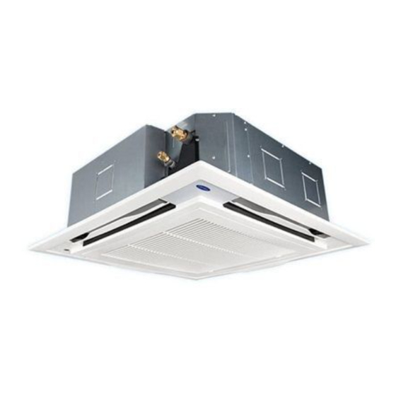
4-Way Cassette air conditioner
Model name:
40TGF____UP
Notice:
quality and reliability standards, and to meet local regulations and market requirements. All
features and specifications are subject to change without prior notice.
is committed to continuously improving its products to ensure the highest
Installation
Manual
1115350146
Installation Manual
1
English
2
5
Advertisement
Chapters
Table of Contents

Related Manuals for Carrier 40TGF UP Series


Summary of Contents for Carrier 40TGF UP Series
- Page 1 1115350146 4-Way Cassette air conditioner Model name: 40TGF____UP Installation Manual Notice: is committed to continuously improving its products to ensure the highest quality and reliability standards, and to meet local regulations and market requirements. All features and specifications are subject to change without prior notice. Installation Manual English...
-
Page 2: Table Of Contents
– 1 – Contents Original instruction Please read this Installation Manual carefully before installing the Air Conditioner. 1 Precautions for safety ..........3 •... - Page 3 Thank you for purchasing this air conditioner. Definition of Protective Gear Please read carefully through these instructions that contain important information which complies with the When the air conditioner is to be transported, installed, maintained, repaired or removed, wear protective gloves Machinery Directive (Directive 2006/42/EC), and ensure that you understand them.
-
Page 4: Precautions For Safety
– 3 – Precautions for safety Warning indications on the air conditioner unit The manufacturer shall not assume any liability for the damage caused by not observing the description of this manual. WARNING WARNING WARNING ELECTRICAL SHOCK HAZARD ELECTRICAL SHOCK HAZARD General Disconnect all remote Disconnect all remote electric power supplies before servicing. - Page 5 • Wear protective gloves and safety work clothing during Selection of installation location installation, servicing and removal. • When the air conditioner is installed in a small room, provide • Do not touch the aluminium n of the unit. You may injure appropriate measures to ensure that the concentration of yourself if you do so.
- Page 6 – 5 – • Follow the instructions in the Installation Manual to install the Electrical wiring • Only a quali ed installer (*1) or quali ed service person (*1) is air conditioner. Failure to follow these instructions may cause allowed to carry out the electrical work of the air conditioner. the product to fall down or topple over or give rise to noise, Under no circumstances must this work be done by an vibration, water leakage or other trouble.
- Page 7 Test run • After the installation work, follow the Owner’s Manual to explain • Before operating the air conditioner after having completed the to the customer how to use and maintain the unit. work, check that the electrical control box cover of the indoor Relocation unit and service panel of the outdoor unit are closed, and set •...
-
Page 8: Accessory Parts
– 7 – Accessory parts Selection of installation place ’ WARNING l l a Install the air conditioner at enough strong place to withstand the weight of the unit. If the strength is not enough, the unit may fall down resulting in injury. s ’... - Page 9 Installation space Ceiling height (Unit:mm) Secure the specified space in the figure for installation and servicing. Model Possible installed ceiling height 0131UP, 0181UP, 0241UP, 0301UP UP to 3.8 m Model A mm 0361UP, 0401UP, 0481UP, 0601UP UP to 4.6 m 0131UP, 0181UP, 0241UP, 0301UP 271 or more 0361UP, 0401UP, 0481UP, 0601UP...
-
Page 10: Installation
– 9 – Installation Discharge direction As shown in the figure below, air discharge directions can be selected according to the shape of the room and REQUIREMENT the location of the indoor unit installation. Strictly comply with the following rules to prevent damage of the indoor units and human injury. Do not put a heavy article on the indoor unit. - Page 11 Opening a ceiling and When hanging a ceiling, open the ceiling along the Existing concrete slab outside dimensions of the installation pattern. installation of hanging bolts Use a hole-in anchors, hole-in plugs, or a hole-in bolts. Consider the piping / wiring after the unit is hung Indoor unit when determining the location of the indoor unit installation and orientation.
-
Page 12: Drain Piping Work
– 11 – Drain piping work Wireless remote controller REQUIREMENT Before installation of the indoor unit, be sure to remove The standard distance for signal reception is For length of the traversing drain pipe, restrict to 20 m the cushion for transportation between the fan and the approximately 8 m vertically against the signal CAUTION or less. - Page 13 Connecting drain pipe Check the draining Perform heat insulating After the electric work has finished, pour water during COOL mode operation. Connect a hard socket (Locally procured) to the hard In the test run, check that water drain is properly As shown in the figure, cover the flexible hose and If the electric work has not yet finished, pull out the socket of the attached supplied flexible hose.
-
Page 14: Refrigerant Piping
– 13 – Refrigerant piping The sealed gas was sealed at the atmospheric REQUIREMENT pressure so when the flare nut is removed, there will Connecting refrigerant piping Charging an excessive or too little amount of no “whooshing” sound: This is normal and is not refrigerant causes a trouble of the compressor. -
Page 15: Electrical Connection
Electrical connection Wire connection REQUIREMENT WARNING Be sure to connect the wires matching the terminal numbers. Incorrect connection causes an error. Use the specified wires for wiring connect the terminals. Securely fix them to prevent external forces applied Be sure to pass the wires through the bushing of wiring connection port of the indoor unit. to the terminals from affecting the terminals. - Page 16 – 15 – Wired remote Controller Wiring (When a wired remote controller System interconnection terminal block is installed) Side D (Space: 8.5 mm) 1 2 3 Side C (Space: 4 mm) For details of wiring / installation of the remote controller, refer to the installation manual enclosed to in the remote controller.
-
Page 17: Applicable Controls
Applicable controls Installing indoor unit on high Procedure Each time you push button, indoor unit ceiling A wired remote controller is required for applicable controls. numbers in the control group change cyclically. Select Purchase a wired remote controller (sold separately). the indoor unit you want to change settings for. - Page 18 – 17 – Filter sign setting Push button to check the setting. Louver lock (No swing) About “Dual swing” The display state changes from flashing to “Dual” means that louvers 01 and 03 are directed According to the installation condition, the lighting time lighting, and the setting is fixed.
- Page 19 Cancelling louver lock Wired remote controller Group control To recognize the position of the switch monitoring function corresponding indoor unit though the Set the wind direction to “0000” of the louver lock setup One wired remote controller can control maximum 8 indoor unit No.
-
Page 20: Test Run
– 19 – Test run Procedure After confirmation, push button to return the mode to the usual mode. Before test run Procedure When pushing button, the display disappears and the status becomes the usual stop status. Cooling test run Before turning on the power supply, carry out the (When pushing button the operation from the After confirming a signal receiving sound “Pi”... -
Page 21: Maintenance
Maintenance Signal receiving unit Procedure Using button, select the operation mode, When TEMPORARY button is pushed for 10 [COOL]. Cleaning air filters The fan is running for self cleaning maintenance after seconds or more, “Pi!” sound is heard and Do not run the air conditioner in a mode other than running the cooling or dry mode. - Page 22 – 21 – Close the air intake grille. Mount the discharge louver. NOTE Close the air intake grille, slide the knob outward, First push in one side of the louver, and then insert Annual maintenance and fix the air intake grille securely. the other side sagging the centre downward.
-
Page 23: Troubleshooting
Troubleshooting Check codes and parts to be checked Procure a wired remote controller (sold separately) and diagnose failure. Wired Wireless remote Temporally troubleshooting can be done with LED display on signal receiving unit. For remote controller controller Sensor block display of detail troubleshooting determination, connect a wired remote controller and diagnose display receiving unit... - Page 24 – 23 – Wired Wireless remote Wired Wireless remote remote controller remote controller controller Sensor block display of controller Sensor block display of display receiving unit display receiving unit Judging Judging Main defective parts Parts to be checked / error description conditioner Main defective parts Parts to be checked / error description...
-
Page 25: Appendix
Appendix 5. When a commercially available dryer is attached to the Work instructions existing pipes. The existing R22 and R410A piping can be reused for There is the possibility that copper green rust has inverter R32 product installations. Existing pipes: Cannot be used. been generated. - Page 26 – 25 – สารบั ญ คำแนะนำเบื ้ อ งต น 1 ข อ ควรระวั ง เพื ่ อ ความปลอดภั ย ....................27 โปรดอ า นค ู ม ื อ การติ ด ตั ้ ง นี ้ อ ย า งละเอี ย ดก อ นการติ ด ตั ้ ง เครื ่ อ งปรั บ อากาศ •...
- Page 27 ขอบคุ ณ ที ่ เ ลื อ กซื ้ อ เครื ่ อ งปรั บ อากาศ คํ า อธิ บ ายอุ ป กรณ ป อ งกั น โปรดอ า นคํ า แนะนํ า ต า งๆ ที ่ ม ี ข อ มู ล สํ า คั ญ ซึ ่ ง ตรงตาม Machinery Directive (Directive 2006/42/EC) อย า งละเอี ย ดถี ่ ถ ว น และโปรด สวมถุ...
-
Page 28: ข อ ควรระวั ง เพื ่ อ ความปลอดภั ย
– 27 – สั ญ ลั ก ษณ ค ํ า เตื อ นบนชุ ด เครื ่ อ งปรั บ อากาศ ข อ ควรระวั ง เพื ่ อ ความปลอดภั ย ■ ผู ้ ผ ลิ ต ไม่ ข อรั บ ผิ ด ชอบต่ อ ความเสี ย หายที ่ ม ี ส าเหตุ ม าจากการละเลยไม่ สั... - Page 29 ก�รเลื อ กสถ�นที ่ เ พื ่ อ ทำ � ก�รติ ด ตั ้ ง สวมถุ ง มื อ ป้ อ งกั น และเสื ้ อ ผ้ า ที ่ ป ลอดภั ย สำ า หรั บ การทำ า งานขณะทำ า การ •...
- Page 30 – 29 – ควรต้ อ งใช้ ก ๊ า ซไนโตรเจนเพื ่ อ ทดสอบการตรวจรอยร ่ ั ว ไม่ ใ ห้ อ ากาศเข้ า หากพ ื ้ น ท ี ่ ด ั ง กล ่ า วไม ่ ส ามารถร ั บ น ำ ้ า หน ั ก ได ้ เ พ ี ย งพอ ต ั ว เคร ื ่ อ งอาจร ่ ว งหล ่ น •...
- Page 31 คำ � อธิ บ �ยสำ � หรั บ ผู ้ ใ ช้ คู ่ ม ื อ การติ ด ตั ้ ง การไม่ ก ระทำ า ตามอาจส่ ง ผลให้ เ สี ย ชี ว ิ ต จากการถู ก ไฟ ช็ อ ต หรื...
- Page 32 – 31 – ข้ อ ควรระวั ง เครื ่ อ งปรั บ อ�ก�ศเครื ่ อ งนี ้ ใ ช้ ต ั ว ทำ � คว�มเย็ น HFC (R32) ซึ ่ ง ไม่ ท ำ � ล�ย ชั ้ น โอโซน เนื...
-
Page 33: ชิ ้ น ส ว นอุ ป กรณ เ สริ ม
ชิ ้ น ส ว นอุ ป กรณ เ สริ ม การเลื อ กสถานที ่ ต ิ ด ตั ้ ง ชื ่ อ ชิ ้ น ส ว น จํ า นวน รู ป ร า ง การใช ง าน คํ... - Page 34 – 33 – พื ้ น ที ่ ต ิ ด ตั ้ ง ความสู ง ของเพดาน (หน ว ย : มม.) ■ ■ เตรี ย มพื ้ น ที ่ ส ํ า หรั บ การติ ด ตั ้ ง และการซ อ มบํ า รุ ง ตามที ่ ก ํ า หนดไว ใ นภาพ รุ...
-
Page 35: การติ ด ตั ้ ง
ทิ ศ ทางการเป า ลม การติ ด ตั ้ ง ■ คุ ณ สามารถเลื อ กทิ ศ ทางการเป า ลมตามรู ป แบบของห อ งและที ่ ตั ้ ง ของตั ว เครื ่ อ งภายในได ต ามรู ป ที ่ แ สดงด า นล า ง ข... - Page 36 – 35 – การเป ด ช อ งเพดานและการติ ด ตั ้ ง สลั ก • ขณะแขวนตั ว เครื ่ อ งบนเพดาน ให เ ป ด ฝ า เพดานตามขนาด แผ น คอนกรี ต ที ่ ม ี อ ยู เ ดิ ม ■...
-
Page 37: งานติ ด ตั ้ ง ท อ ระบาย
ข อ กํ า หนด รี โ มทคอนโทรลไร ส าย • สํ า หรั บ ความยาวของท อ ที ่ พ าดขวาง ควรจํ า กั ด อยู ท ี ่ 20 ม. งานติ ด ตั ้ ง ท อ ระบาย ■... - Page 38 – 37 – การต อ ท อ ระบายนํ ้ า การตรวจสอบการระบายนํ ้ า • หลั ง จากทํ า งานที ่ เ กี ่ ย วกั บ ไฟฟ า เสร็ จ แล ว ให เ ทนํ ้ า ระหว า งที ่ การใช...
-
Page 39: ท อ ส ง สารทํ า ความเย็ น
ท อ ส ง สารทํ า ความเย็ น ข อ ควรระวั ง ข อ ควรระวั ง ห้ า มขี ด ข่ ว นพื ้ น ผิ ว ภายในของส่ ว นที ่ บ านออก เมื ่ อ กำจั ด การขั น น็ อ ตโดยใช แ รงมากเกิ น อาจทํ า ให น ็ อ ตแตกขึ ้ น อยู ก ั บ การต... -
Page 40: การต อ สายไฟ
– 39 – การต อ สายไฟ ขั ้ น ตอนการใช ฉ นวนกั น ความร อ น ใช ท อ ฉนวนกั น ความร อ นแยกกั น ระหว า งด า นของเหลวและ คํ า เตื อ น ด า นก า ซ •... - Page 41 การต อ สายไฟ ■ บล็ อ คขั ้ ว ต อ ที ่ เ ชื ่ อ มระบบ เข า ด ว ยกั น ข อ กํ า หนด ด า น D (เว น ที ่ ว า ง 8.5 มม.) ด...
-
Page 42: การควบคุ ม ด ว ยรี โ มทแบบใช ส าย
– 41 – การเดิ น สายไฟรี โ มทคอนโทรลแบบใช ส าย (เมื ่ อ มี ก ารติ ด ตั ้ ง รี โ มทคอนโทรลแบบใช ส าย) การควบคุ ม ด ว ยรี โ มทแบบใช ส าย ■ • สํ า หรั บ รายละเอี ย ดเกี ่ ย วกั บ การเดิ น สายไฟ/การติ ด ตั ้ ง รี โ มทคอนโทรล โปรดดู ค ู ม ื อ การติ ด ตั ้ ง ที ่ แ นบมากั บ รี โ มทคอนโทรล ควรใช... - Page 43 ขั ้ น ตอนที ่ การติ ด ตั ้ ง ตั ว เครื ่ อ งภายในบนเพดานสู ง การต ั ้ ง ค า สั ญ ญาณเตื อ นทํ า ความสะอาด กดปุ ม เพื ่ อ ทํ า การตั ้ ง ค า ให เ สร็ จ สมบู ร ณ สภาพ ■...
- Page 44 – 43 – • เกี ่ ย วกั บ “การส า ยสองทิ ศ ทาง” การล็ อ กบานเกล็ ด (ไม ส า ย) การยกเลิ ก การล็ อ กบานเกล็ ด ฟ ง ก ช ั น การตรวจสอบสวิ ต ช ■ ■ ■...
- Page 45 การควบคุ ม เป น กลุ ม หากต อ งการจดจํ า ตํ า แหน ง ของตั ว เครื ่ อ งภายใน ขั ้ น ตอนที ่ ■ หลั ง ยื น ยั น แล ว ให ก ดปุ ม เพื...
-
Page 46: การทดสอบการทํ า งาน
– 45 – ขั ้ น ตอนที ่ ตั ว รั บ สั ญ ญาณ ขั ้ น ตอนที ่ การทดสอบการทํ า งาน ◆ กดปุ ม แล ว เลื อ กโหมดการทํ า งาน [COOL] การทดสอบการทํ า ความเย็ น เมื ่ อ กดปุ ม TEMPORARY ค า งไว 10 วิ น าที ขึ ้ น ไป •... -
Page 47: การบํ า รุ ง รั ก ษา
ป ด ตะแกรงช อ งลมเข า ยึ ด บานเกล็ ด ช อ งลมออก การบํ า รุ ง รั ก ษา ป ด ตะแกรงช อ งลมเข า เลื ่ อ นปุ ม ออกด า นนอก แล ว ยึ ด เริ ่ ม จากการกดด า นหนึ ่ ง ของบานเกล็ ด ช อ งลมก อ น แล ว จึ ง ตะแกรงช... -
Page 48: การแก ไ ขป ญ หา
– 47 – ข อ สั ง เกต การแก ไ ขป ญ หา การบํ า รุ ง รั ก ษาประจํ า ป หาซื ้ อ รี โ มทคอนโทรลแบบใช ส าย (แยกจํ า หน า ย) และวิ น ิ จ ฉั ย เหตุ ข ั ด ข อ ง •... - Page 49 รหั ส การตรวจสอบและชิ ้ น ส ว นที ่ ต อ งตรวจสอบ หน า จอ ■ รี โ มทคอนโทรลไร ส าย ของรี โ มท หน า จอบล็ อ คเซ็ น เซอร สถานะ คอนโทรล ของตั ว รั บ สั ญ ญาณ อุ...
- Page 50 – 49 – หน า จอ หน า จอ รี โ มทคอนโทรลไร ส าย รี โ มทคอนโทรลไร ส าย ของรี โ มท ของรี โ มท หน า จอบล็ อ คเซ็ น เซอร หน า จอบล็ อ คเซ็ น เซอร สถานะ สถานะ...
-
Page 51: ภาคผนวก
ภาคผนวก คำ า ชี ้ แ จงการใช้ ง าน 5. หากมี อ ุ ป กรณ์ ด ู ด ความชื ้ น ติ ด ตั ้ ง อยู ่ ใ นท่ อ สารทำ า ความเย็ น 㪋 ท ที ่ อ ่ ง... - Page 52 – 51 – MEMO ..........................................................................................................................................................................................................................................................................................................................................................................................................................................................................................................................................................................................................................................................................................................................................................
- Page 53 MEMO ....................................................................................................................................................................................................................................................................................................................................................................................................................................................................................................................................................................................................................................................................................................................................................................................................................
- Page 54 – 53 – MEMO ..........................................................................................................................................................................................................................................................................................................................................................................................................................................................................................................................................................................................................................................................................................................................................................
- Page 56 Installation Manual Model name: 40TGF____UP 1115350146...
Need help?
Do you have a question about the 40TGF UP Series and is the answer not in the manual?
Questions and answers