Table of Contents
Advertisement
Quality Assurance
Certificate Reg. No:
04 100 950420
Subject to change without notice
Manufacturer's Name: Saudi Airconditioning Manufacturing Co. Ltd.
Country of origin : Jeddah, Saudi Arabia
Nearest port of embarkation: Jeddah Islamic port
Product classification: Commercial and Residential
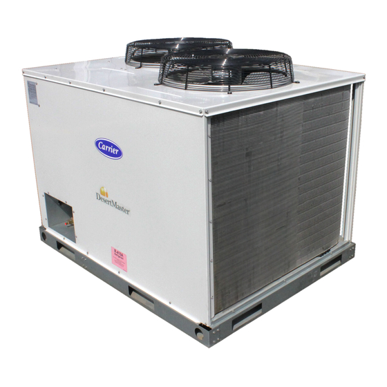
38AUM Air Cooled Condensing Units – 50Hz
The 38AUM series outdoor air cooled condensing units matched with Carrier's 40RUM series indoor air handler's offer
a wide variety of options for your HVAC application needs. Whether it's first cost with the 38AUM single compressor
models or superior part load performance from the two compressor models, this series is designed for long,
dependable operation as a rooftop or on-the-ground installation. All 38AUM and 40RUM series units use
environmentally sound Puron ® R-410A refrigerant. Together, they create a reliable split system that provides easy
solutions to a wide range of commercial HVAC needs.
Contact your local Carrier representative for additional reference materials.
38AUM Air Cooled Condensing Units – 50Hz
Nominal Cooling Capacity 6.0 – 15.0 Tons
HFC R -410A Refrigerant
Page 1
Installation Operation Maintenance Manual
Advertisement
Table of Contents

Related Manuals for Carrier 38AUM Series


Summary of Contents for Carrier 38AUM Series
- Page 1 HFC R -410A Refrigerant The 38AUM series outdoor air cooled condensing units matched with Carrier’s 40RUM series indoor air handler’s offer a wide variety of options for your HVAC application needs. Whether it’s first cost with the 38AUM single compressor models or superior part load performance from the two compressor models, this series is designed for long, dependable operation as a rooftop or on-the-ground installation.
-
Page 2: Table Of Contents
Warranty is based on the general terms and conditions of the manufacturer. Any modifications to the design and/or installation made without discussion with Carrier and without advance written agreement will result in the loss of the right to any warranty claims and any claim for injury to personnel as a result of these modifications. - Page 3 WARNING CAUTION ELECTRIC SHOCK HAZARD CUT HAZARD Failure to follow this warning could cause Failure to follow this warning could cause personal injury or death. personal injury. Before performing service or maintenance Sheet metal parts may have sharp edges or operations on unit, always turn off main burrs.
-
Page 4: Unit Physical Data
UNIT PHYSICAL DATA (ENGLISH UNITS) Unit 38AUM Refrigeration System Puron ® No. of Ckt / No. of Comp. / Type 1 / 1 / Scroll 2 / 2 / Scroll Initial Charge per Circuit (Ib) 7.72 8.16 7.05 / 7.05 9.03 / 9.70 12.57 / 11.57 Operating Charge per Circuit (Ib) -
Page 5: Base Unit Dimensions
BASE UNIT DIMENSIONS – 38AUM Series Size Z07-D14 FRONT VIEW RIGHT SIDE VIEW LEFT SIDE VIEW Center of Gravity Service Valve Unit Height (mm) Unit (mm) Connections Weight 38AUM (kg) Suction Liquid 176.0 1165.0 457.2 609.6 533.4 1-1/8 177.0 1165.0 457.2... - Page 6 BASE UNIT DIMENSIONS – 38AUM Series Size D16 TOP VIEW LEFT SIDE VIEW - Center Of Gravity - Direction of Air Flow FRONT Height Center of Gravity Service Valve Unit Unit (mm) (mm) Connections 38AUM Weight (kg) Suction Liquid 332.0 1339 965.2...
-
Page 7: Installation Guideline
INSTALLATION GUIDELINE Replacement/Retrofit – R-22 to Puron® Replacement/retrofit installations require change-out of outdoor unit, metering device, and filter driers. Change-out of indoor coil (evaporator) and interconnecting tubing is recommended. Existing evaporator coil – If the existing evaporator coil may be re-used, check with the coil manufacturer to verify the coil construction is suitable for operation with the higher pressures of Puron®... - Page 8 Matching 38AUM Model to Evaporator Coil The Model 38AUMZ is a single-circuit unit design, requiring one set of refrigeration piping. This model can be connected to an evaporator coil with one circuit or with two circuits (by manifolding the evaporator connections into a single piping system).
- Page 9 Step 2 — Complete Pre-Installation Checks Check Unit Electrical Characteristics: Confirm before installation of unit that voltage, amperage and circuit protection requirements listed on unit data plate agree with power supply provided. Un-crate Unit: Remove unit packaging except for the top skid assembly, which should be left in place until after the unit is rigged into its final location.
- Page 10 See Equivalent Lengths for Common Fittings (EN units), Equivalent Lengths for Common Fittings, for usual fitting types. Also identify adjustments for refrigeration specialties. Refer to Part 3 of the Carrier System Design Manual for additional data and information on equivalent lengths. Equivalent Lengths for Common Fittings (EN units)
- Page 11 Vertical Separation (outdoor unit above indoor unit) Vertical elevation difference of 60 m (200 ft) is permitted when the outdoor unit (38AUMZ or 38AUMD) is located above the indoor unit. Insulate Suction Lines Apply closed-cell tubular insulation to all suction lines between evaporator coil connection and 38AUM unit’s suction service valve.
- Page 12 40RUM 40RUM Coil Cooling Stage Connect to 38AUMD Arrangement Segment Circuit 1 Vertical Circuit 2 Circuit 1 Horizontal Circuit 2 Fig: - Typical Evaporator Coil Connections (40RUM) Install Filter Drier(s) and Moisture Indicator(s) Every unit MUST have a filter drier in the liquid line. 38AUMD models require two filter driers (one in each liquid line). Locate the filter drier(s) at the indoor unit, close to the evaporator coil’s thermal expansion valve (TXV) inlets.
- Page 13 Fig: - Location of Sight Glass(es) and Filter Driers Typical 38AUMD Systems Install Liquid Line Solenoid Valve It is recommended that a solenoid valve be placed in the main liquid line (see Figs: - Location of Sight Glass(es) and Filter Driers Typical 38AUMZ/D Systems) between the condensing unit and the evaporator coil. Locate the solenoid valve at the outlet end of the liquid line, near the evaporator coil connections, with flow direction arrow pointed at the evaporator coil.
- Page 14 Fig: - Typical Piping Connection Assembly When connecting the field tubing to the 38AU service valves, wrap the valves in wet rags to prevent overheating Pressure-test all joints from outdoor unit connections over to the evaporator coil, using nitrogen as pressure and with soap-and-bubbles.
- Page 15 Circuit 1: 24.5 – 14.7 = 9.8 lbs Circuit 2: 22.9 – 13.7 = 9.2 lbs For linear line lengths longer than 125 ft (38 m), contact your local Carrier representative for system charge value. Step 7 — Install Accessories Accessories requiring modifications to unit wiring should be completed now.
- Page 16 (air handler or packaged fan coil). Fig: - Typical Remote Thermostat Connection depict typical connections to a Carrier 40RUM fan coil unit. Plan for field connections carefully and install control wiring correctly per the project plan. Additional components and supplemental transformer accessory may be required.
- Page 17 The 38AUMD is a dual-circuit, two-stage cooling unit. Select a two—stage cooling thermostat, with or without supplemental heating as needed. Fig: - Typical Remote Thermostat Connections — 38AUMD Select a thermostat cable or equivalent single leads of different colors with minimum of five leads for 38AUMZ or six leads for 38AUMD unit.
- Page 18 PRE-START-UP IMPORTANT: Before beginning Pre-Start-Up or Start-Up, review Start-Up Checklist at the back of this book. The Checklist assures proper start-up of a unit and provides a record of unit condition, application requirements, system information, and operation at initial start-up. CAUTION UNIT DAMAGE HAZARD Failure to follow this caution may result in equipment damage.
- Page 19 START-UP 38AUM Units: The compressor crankcase heater must be on for 24 hours before start-up. After the heater has been on for 24 hours, the unit can be started. If no time elapsed since the preliminary charge step was completed, it is unnecessary to wait the 24-hour period.
- Page 20 Adjust Refrigerant Charge — Refer to Cooling Charging Charts. For applications with line lengths greater than 125 ft (38 m), contact Carrier representative. Make sure that all condenser fans are operating, and on units with the HGBP (hot pass bypass) option make sure that the HGBP solenoid valve is deactivated (see procedure below), before adjusting charge to the charging charts.
- Page 21 OPERATING SEQUENCE Base Unit Controls Indoor (Supply) Fan— The indoor fan contactor (IFC) is remotely located at the fan coil or fan section. If the thermostat fan operation is selected as Continuous, the IFC is energized and the indoor (supply) fan motor runs continuously.
-
Page 22: Routine System Maintenance/Service
ROUTINE SYSTEM MAINTENANCE These items should be part of a routine maintenance program, to be checked every month or two, until a specific schedule for each can be identified for this installation: Quarterly Inspection (and 30 days after initial start) — Indoor section •... - Page 23 Refrigeration System CAUTION EQUIPMENT DAMAGE HAZARD Failure to follow this caution may result in equipment damage. This system uses Puron® refrigerant which has higher pressures than R-22 and other refrigerants. No other refrigerant may be used in this system. Gage set, hoses, and recovery system must be designed to handle Puron. If you are unsure consult the equipment manufacturer.
- Page 24 Comfort Alert Diagnostic Module The Comfort Alert Diagnostic Module (CADM) monitors and analyzes data from the Copeland Scroll® three-phase compressor and the thermostat demand. The CADM also provides a 3-minute anti-recycle time delay to compressor cycling. Each compressor has a separate CADM module. The CADM detects causes for electrical and system related failures without any sensors.
- Page 25 Table - LED Status Codes Status LED Status LED Description Status LED Troubleshooting Information Green “POWER” Module has power Supply voltage is present at module terminals Red “TRIP” LED Thermostat demand signal Y is 1. Compressor protector is open On Solid present, but the compressor is not 2.
- Page 26 Table – CADM Troubleshooting Miswired Module Indication Recommended Troubleshooting Action Green LED is not on, module Determine if both R and C module terminals are connected. Verify voltage in present at module’s R does not power up and C terminals. NOTE: The CADM requires a constant nominal 24VAC power supply.
- Page 27 Periodic cleaning with Totaline® environmentally sound coil cleaner is essential to extend the life of RTPF coils. This cleaner is available from Carrier Replacement parts division as part number P902-0301 for a one gallon container, and part number P902-0305 for a 5 gallon container. It is recommended that all RTPF coils be cleaned with the Totaline environmentally sound coil cleaner as described below.
- Page 28 Totaline Environmentally Sound Coil Cleaner Application Instructions: Note: Proper eye protection such as safety glasses is recommended during mixing and application. 1. Turn off unit power. 2. Remove screws holding rear corner post and top cover in place. Pivot top cover up 12 to 18 inches (305 to 457 mm) and support with a rigid support.
-
Page 29: Piping Recommendation
DNU Do Not Use (pressure drop exceeds available subcooling in this model) NOTE: For applications with equivalent length greater than 188 ft (57 m) and/0r linear length greater than 125 ft (38 m), contact your local Carrier representative. Page 29... -
Page 30: Electrical Data Table
ELECTRICAL DATA TABLE Single Circuit Unit - 400V-3Ph-50Hz VOLTAGE RANGE COMP 1 COMP 2 OFM (ea) POWER SUPPLY Unit MOCP 38AUMZ07 13.5 38AUMZ08 12.2 18.9 Dual Circuit Unit - 400V-3Ph-50Hz VOLTAGE RANGE COMP 1 COMP 2 OFM (ea) POWER SUPPLY V-Ph-Hz MOCP 38AUMD12... - Page 31 TYPICAL WIRING SCHEMATIC – 38AUMZ07/08 Page 31...
- Page 32 TYPICAL WIRING SCHEMATIC – 38AUMD12/14 Page 32...
-
Page 33: Typical Wiring Schematic
TYPICAL WIRING SCHEMATIC – 38AUMD16 Page 33... -
Page 34: Charging Chart
CHARGING CHARTS Page 34... - Page 35 CHARGING CHARTS (cont.) CHARGING CHARTS (cont.) CHARGING CHARTS (cont.) CHARGING CHARTS (cont.) CHARGING CHARTS (cont.) CHARGING CHARTS (cont.) CHARGING CHARTS (cont.) Page 35...
- Page 36 CHARGING CHARTS (cont.) Page 36...
- Page 37 CHARGING CHARTS (cont.) Page 37...
-
Page 38: R-410A Refrigerant Quick Reference Guide
ATTENTION INSTALLERS AND SERVICE TECHNICIANS! R-410A Refrigerant Quick Reference Guide • R-410A refrigerant operates at 50-70 percent higher pressures than R-22. Be sure that servicing equipment and replacement components are designed to operate with R-410A refrigerant. • R-410A refrigerant cylinders are rose colored. •... - Page 39 Troubleshooting Guide Cooling Service Analysis REMEDY PROBLEM CAUSE Power failure. Call power company. Fuse blown or circuit breaker tripped. Replace fuse or reset circuit breaker. Defective thermostat, contactor, transformer, or Replace component. Compressor and condenser fan will not control relay. start.
-
Page 40: Mandatory Startup Checklist And Record
This page is a mandatory checklist & record – the check to be executed and data to be recorded for future reference incase of failure. A copy of this checklist data has to be submitted to carrier representative. Completion of this checklist is a must for any field claim, no field support will be provided for incomplete or blank checklists. - Page 41 NOTES Page 41...
- Page 42 NOTES Page 42...
- Page 43 NOTES Page 43...
- Page 44 Manufacturer reserves the rights to discontinue or change at any time, specifications or designs without notice and without incurring any obligations. Supersedes Version: 38AUM-50Hz-IOMV2 Catalog Number: 38AUM-50Hz-IOMV3 Page 44 Effective Date: 04-09-2016 Phase: 50Hz...
Need help?
Do you have a question about the 38AUM Series and is the answer not in the manual?
Questions and answers