Table of Contents
Advertisement
40MKCB**C/24AHA4
40MKCB**C/124ANS
40MKQB**C/25HHA4
40MKQB**C/224ANS
Cassette Ductless Split
Sizes 18 to 34
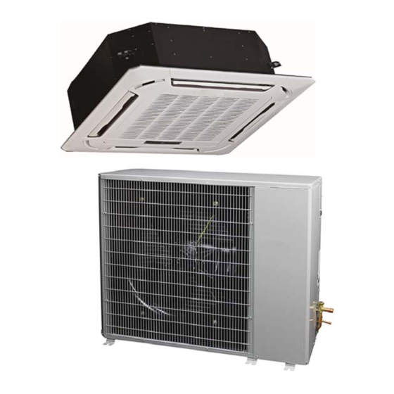
Fig. 1 - - Indoor Unit, Outdoor Unit, and Remote Control
NOTE: Read the entire instruction manual before starting the
installation.
Installation Instructions
TABLE OF CONTENTS
WARNING
!
UNIT OPERATION AND SAFETY HAZARD
Failure to follow this warning could result in personal injury or
equipment damage.
Puron refrigerant systems operate at higher pressures than
standard R- -22 systems. To avoid damage to the unit or
possible personal injury, do not use R- -22 service equipment or
components on Puron refrigerant equipment.
SAFETY CONSIDERATIONS
Improper installation, adjustment, alteration, service, maintenance,
or use can cause explosion, fire, electrical shock, or other
conditions which may cause death, personal injury, or property
damage. Consult a qualified installer, service agency, or your
distributor or branch for information or assistance. The qualified
installer or agency must use factory- -authorized kits or accessories
when modifying this product. Refer to the individual instructions
packaged with the kits or accessories when installing.
Follow all safety codes. Wear safety glasses, protective clothing, and
work gloves. Use quenching cloth for brazing operations. Have a fire
extinguisher available. Read these instructions thoroughly and follow
all warnings or cautions included in the unit literature and on labels
attached to the unit. Consult local building codes and current editions
of the National Electrical Code ( NEC ) NFPA 70. In Canada, refer to
current editions of the Canadian electrical code CSA 22.1.
Recognize safety information. This is the safety- -alert symbol
When you see this symbol on the unit and in instructions or manuals,
be alert to the potential for personal injury. Understand these signal
words; DANGER, WARNING, and CAUTION. These words are
used with the safety- -alert symbol. DANGER identifies the most
serious hazards which will result in severe personal injury or death.
WARNING signifies hazards which could result in personal injury or
death. CAUTION is used to identify unsafe practices which may
result in minor personal injury or product and property damage.
1
2
4
5
7
7
7
9
9
12
16
20
23
! !
Advertisement
Table of Contents

Related Manuals for Carrier 40MKCB**C/24AHA4


Summary of Contents for Carrier 40MKCB**C/24AHA4
-
Page 1: Table Of Contents
40MKCB**C/24AHA4 40MKCB**C/124ANS 40MKQB**C/25HHA4 40MKQB**C/224ANS Cassette Ductless Split Sizes 18 to 34 Installation Instructions TABLE OF CONTENTS SAFETY CONSIDERATIONS PARTS LIST DIMENSIONS - - INDOOR DIMENSIONS - - OUTDOOR CLEARANCES - - INDOOR CLEARANCES - - OUTDOOR SYSTEM REQUIREMENTS INSTALLATION INSTALL INDOOR UNIT... -
Page 2: Parts List
PARTS LIST NOTE is used to highlight suggestions which will result in enhanced installation, reliability, or operation. Indoor Unit WARNING TXV Kit The cassette type unit and horizontal discharge unit (24AHA/124ANS and 25HHA4/224ANS) installation would not be complete without ELECTRICAL SHOCK HAZARD the addition of the TXV kit. - Page 3 Table 2 – Indoor Units Parts List Outdoor Unit Name of Part Qty. Usage The following items are included with the outdoor unit: Owner’s Manual Guide for the homeowner Warranty card Warranty information Installation instructions Guide to install the unit Insulation for refrigerant Pipe insulation Material piping...
-
Page 4: Dimensions - Indoor
DIMENSIONS - INDOOR Cassette Grille Cassette Body Drain pipe Refrigerant pipe connector connector Fresh air intake ( Φ75mm) A150291 Fig. 7 - - 40MKC**C, 40MKQ**C Unit and Panel Dimensions Table 4 – Dimensions Indoor Indoor Unit Size Height (H) Width (W) Depth (D) Operating Weight BTU/Hr... -
Page 5: Dimensions - - Outdoor
DIMENSIONS - - OUTDOOR Fig. 8 - - Outdoor Unit Dimensions NOTE: Center of Gravity All dimensions are in “inches” unless noted. MINIMUM UNIT SIZE MOUNTING PAD DIMENSIONS 18,24 23” x 42” 30,36 24” x 50”... -
Page 7: Clearances - - Indoor
CLEARANCES - - INDOOR A150152 Fig. 9 - - 40MKC**B, 40MKQ**B Unit Clearance CLEARANCES - - OUTDOOR SYSTEM REQUIREMENTS 1. Single Unit Applications: With coil facing wall: Allow 6” Clearances (152.4mm) minimum clearance on coil side and coil end and Allow sufficient space around the indoor and outdoor unit for 20”... -
Page 8: User Interface
Condensate Drain Pipe Sizes Communication Wiring: Refer to table 11 for the required sizes. A separate shielded copper conductor only with a minimum 300 volt rating and 2/64- -inch thick insulation must be used as the Table 11 – Drain Pipe Sizes communication wire from the outdoor unit to the indoor unit. -
Page 9: Installation
INSTALLATION 2. TXV Installation a. Location - - The TXV kit can be affixed directly to the Complete Pre- -installation Checks indoor unit or anywhere between 12 to 18 inches from 1. Unpack Unit - - Store the indoor and outdoor units in the orig- the indoor unit pipe connection. - Page 10 c. Once location and flow direction is identified, connect piping between indoor unit and TXV kit. Flexible pip- ing is recommended. Liquid pipe CAUTION Refrigerant Flow Direction indoor unit Failure to follow the following caution may result in equipment outdoor damage or improper operation.
- Page 11 d. Screw the nuts to suspend the unit. Check the lower side of indoor unit locates at position (10 to 12 mm) higher than the lower surface of the ceiling. L is about half of the screw length of the installation hook. e.
-
Page 12: Install Outdoor Unit
f. Hang the hook behind the air inlet grille on to the panel. g. Connect the display connector to the corresponding plug on the main body (see Fig. 25). h. Close the air inlet grille. Outdoor i. Press the installation cover gently into the panel. Indoor Fig. - Page 13 Connection at Outdoor Unit CAUTION UNIT DAMAGE HAZARD Failure to follow this caution may result in equipment damage or improper operation. To prevent damage to unit or service valves observe the following: S A brazing shield MUST be used. S Wrap service valves with wet cloth or use a heat sink material.
- Page 14 Power Wiring NOTE: The indoor and outdoor units are powered separately. 1. Mount indoor and outdoor power disconnect. The units are factory wired for the voltage shown on the unit nameplates. The fused disconnect switch must be provided within sight of the unit, readily accessible, but out of reach of children.
- Page 15 Fig 33 and 34. A150303 Fig. 33 - - Strain Relief Bracket A150280 Fig. 31 - - 40MKCB**C/24AHA4 or 124ANS Connecting Diagram A150304 Fig. 34 - - Strain Relief Bracket Affixed to Cassette Body A150282 Fig.
-
Page 16: Electrical Data
ELECTRICAL DATA Table 17 – 24AHA4/124ANS Electrical Data MAX FUSE** OPER VOLTS* COMPR Unit Size - - V/PH or CKT BRK voltage series AMPS 18- -30 56.3 0.50 11.8 24- -30 62.9 10.9 0.50 14.1 208/230/1 30- -30 73.0 14.1 0.70 18.3 36- -30... - Page 17 JR 6 Legend: To C C M ....Model sp ecific fe ature C omm.B us CN 1: Live wire L1/Null line L2 CN 17: Null line C CN111 :Comp ressor si gnal CN 8: Fa n interface CN 6: Co nnectors interface JR 6 CN 23...
- Page 18 JR 6 Legend: To C C M ....Model sp ecific fea ture C omm.B us CN 1: Live wire L1/Null l ine L2 CN 17: Controls 24V sign al interfac e(R/C) CN111 : Signal in terface(Y /O) CN 8:New fan interface CN 6: Co nnectors interface...
- Page 19 Run Power Wiring for Indoor Unit Be sure field wiring complies with local building codes and NEC, and unit voltage is within limits shown in Tables 17 through 20. Contact the local power company for correction of improper line voltage. WARNING ELECTRICAL SHOCK HAZARD Failure to follow this warning could result in personal injury...
-
Page 20: Start- -Up
6. Remove the control box cover and finish all indoor unit 8. Disconnect charge hose from charge connection of the low wiring connections as shown on the wiring diagram or in side service valve. the accessory installation instructions. Replace the control 9. - Page 21 Triple Evacuation Method Test Operation For CASSETTE The triple evacuation method should only be used when vacuum Perform test operation after completing gas leak and electrical pump is only capable of pumping down to 28 in. of mercury safety check. (See Fig. 47) vacuum and system does not contain any liquid water.
- Page 22 To Clean or Replace Air Filters Cover Drain pipe 1. Place a plastic sheet on the floor to catch any water that may connection port spill from drain pan. Stow tube 2. Slide filter out. Water intake 3. Vacuum clean or wash filter with soapy water. Rinse and let air dry.
-
Page 23: Troubleshooting
TROUBLESHOOTING Fault code For ease of service, the indoor unit is equipped with diagnostic code display LEDs in the indoor units. This diagnostic display is a combination of flashing LEDs on the display panel or the front of the unit. If possible, always check the diagnostic codes displayed on the indoor unit. - Page 24 Table 22 – Troubleshooting PROBLEM POSSIBLE CAUSE SOLUTION Unit not energized Check the main power connection. Main switch is set to OFF Check and put it to ON position. Compressor and Fan of Main switch fuses are blown Replace fuses. the Outdoor Unit Will Not Compressor cycling protection is on Wait for 3 minutes.
Need help?
Do you have a question about the 40MKCB**C/24AHA4 and is the answer not in the manual?
Questions and answers