Carrier 40MB C Series Service Manual
Hide thumbs
Also See for 40MB C Series:
- Installation instructions manual (19 pages) ,
- Installation instructions manual (42 pages) ,
- Service manual (76 pages)
Table of Contents
Advertisement
Quick Links
40MB*C
Cassette Ductless System
Sizes 09 to 18
TABLE OF CONTENTS
. . . . . . . . . . . . . . . . . . . . . . . . . . . . . . . . . . .
. . . . . . . . . . . . . . . . . . . . . . . . . . . . . . . . . .
DIMENSIONS/CLEARANCES
. . . . . . . . . . . . . . . . . . . . . . . . . . . . . . . .
. . . . . . . . . . . . . . . . . . . . . . . . . . . . . . . . . . . . . . . . . . .
. . . . . . . . . . . . . . . . . . . . . . . . . . . . . . . .
. . . . . . . . . . . . . . . . . . . . . . . . . . . . . . .
. . . . . . . . . . . . . . . . . . . . . . . . . . . . . .
. . . . . . . . . . . . . . . . . . . . . . . . . . . . . . . . . . . . . . .
SAFETY CONSIDERATIONS
Installing, starting up, and servicing air−conditioning equipment
can be hazardous due to system pressures, electrical components,
and equipment location (roofs, elevated structures, etc.).
Only trained, qualified installers and service mechanics should
install, start−up, and service this equipment.
Untrained personnel can perform basic maintenance functions such
as cleaning coils. All other operations should be performed by
trained service personnel.
When working on the equipment, observe precautions in the literature
and on tags, stickers, and labels attached to the equipment.
Follow all safety codes. Wear safety glasses and work gloves. Keep
quenching cloth and fire extinguisher nearby when brazing. Use
care in handling, rigging, and setting bulky equipment.
Read this manual thoroughly and follow all warnings or cautions
included in literature and attached to the unit. Consult local building
codes and National Electrical Code (NEC) for special requirements.
Recognize safety information. This is the safety−alert symbol
When you see this symbol on the unit and in instructions or manuals,
be alert to the potential for personal injury. Understand these signal
words: DANGER, WARNING, and CAUTION.
Service Manual
. . . . . . . . . . . . . . . . . . . . . . . . .
. . . . . . . . .
. . . . . . . . . . . . . . . . . . . . . .
. . . . . . . . . . . . . . . . . . . . . . . . . . .
. . . . . . . . . . . . . . . . . .
. . . . . . . . . . . . .
These words are used with the safety−alert symbol. DANGER
identifies the most serious hazards which will result in severe personal
PAGE
injury or death. WARNING signifies hazards which could result in
1
personal injury or death. CAUTION is used to identify unsafe
1
practices which may result in minor personal injury or product and
2
property damage. NOTE is used to highlight suggestions which will
3
result in enhanced installation, reliability, or operation.
4−5
!
6
6
ELECTRICAL SHOCK HAZARD
7
Failure to follow this warning could result in personal
8
injury or death.
10
Before installing, modifying, or servicing system, the
10
main electrical disconnect switch must be in the OFF
11
position. There may be more than 1 disconnect switch.
15
Lock out and tag switch with a suitable warning label.
32
!
!
EQUIPMENT DAMAGE HAZARD
Failure to follow this caution may result in equipment
damage or improper operation.
! !
.
Do not bury more than 36 in. (914 mm) of refrigerant pipe
in the ground. If any section of pipe is buried, there must be
a 6 in. (152 mm) vertical rise to the valve connections on
the outdoor units. If more than the recommended length is
buried, refrigerant may migrate to the cooler buried section
during extended periods of system shutdown. This causes
refrigerant slugging and could possibly damage the
compressor at start−up.
INTRODUCTION
This service manual provides the necessary information to service,
repair, and maintain the indoor units. Section 2 of this manual has an
appendix with data required to perform troubleshooting. Use the Table
of Contents to locate a desired topic.
WARNING
WARNING
EXPLOSION HAZARD
Failure to follow this warning could
result in death, serious personal injury,
and/or property damage.
Never use air or gases containing
oxygen for leak testing or operating
refrigerant compressors. Pressurized
mixtures of air or gases containing
oxygen can lead to an explosion.
CAUTION
Advertisement
Table of Contents

Subscribe to Our Youtube Channel
Related Manuals for Carrier 40MB C Series


Summary of Contents for Carrier 40MB C Series
-
Page 1: Table Of Contents
40MB*C Cassette Ductless System Sizes 09 to 18 Service Manual TABLE OF CONTENTS These words are used with the safety−alert symbol. DANGER identifies the most serious hazards which will result in severe personal PAGE injury or death. WARNING signifies hazards which could result in SAFETY CONSIDERATIONS . -
Page 2: Model Serial Number Nomenclatures
MODEL SERIAL NUMBER NOMENCLATURES Table 1—Unit Sizes SYSTEM TONS VOLTAGE/PH/HZ INDOOR MODEL 40MBQB09C--3 208-230/1/60 40MBQB12C--3 40MBQB18C--3 INDOOR UNIT 40 = FAN COIL UNIT VOLTAGE MB = MODEL 3 = 208/230-1-60 SYSTEM TYPE Q = HEAT PUMP B = ALL MODELS NOT USED NOMINAL CAPACITY 09 - 3/4 TON... -
Page 3: Specifications
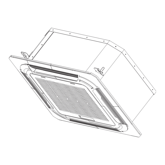
SPECIFICATIONS Table 2—Cassette SIZE System Indoor Model 40MBQB09C--3 40MBQB12C--3 40MBQB18C--3 Voltage, Phase, Cycle V/Ph/Hz 208/230-1-60 208/230-1-60 208/230-1-60 Electrical Power Supply Indoor unit powered from outdoor unit Wireless Remote Controller (°F/°C Convertible) Standard Standard Standard Controls Wired Remote Controller (°F/°C Convertible) Optional Optional Optional... - Page 4 DIMENSIONS Liquid side Gas side Body Drain hole Wiring connection port ( for Service ) E-parts box 4-Screw hole (for install panel) 4-install hanger 21.46(545) 10.24(260) 22.44(570) Drain pipe Outside Air Intake Wiring connection port 1.65(42) 1.65(42) Panel 1.97(50) 25.47(647) Fig.
- Page 5 CLEARANCES Fig. 2 – Indoor Unit Clearance...
-
Page 6: Electrical Data
ELECTRICAL DATA Table 4—Cassette Indoor Unit Electrical Data OPER. VOLTAGE OPER. VOLTAGE INDOOR FAN UNIT SIZE MAX FUSE CB AMP MAX FUSE CB AMP MAX / MIN* V-PH-HZ 0.146 0.061 Refer to outdoor unit installation instructions – 253 / 187 208-230/1/60 0.146 0.061... -
Page 7: Connection Diagram
CONNECTION DIAGRAM Fig. 3 – Connection Diagram Notes: 1. Do not use thermostat wire for any connection between indoor and outdoor units. 2. All connections between indoor and outdoor units must be as shown. The connections are sensitive to polarity and will result in a fault code. -
Page 8: Wiring Diagrams
WIRING DIAGRAMS Fig. 4 – Wiring Diagram Sizes 09 − 12 Table 5—Dimensions Sizes 09 − 12 INDOOR UNIT CODE PART NAME Input: 230VAC High voltage Connection of the terminal Output: 0-5VDC Connection of the CCM Output: 0V Connection of the earth Output: 1-5VDC Connection of the Water level switch Output: 5VDC Connection of the Room and Pipe temperature CN10A... - Page 9 WIRING DIAGRAMS (CONTINUED) Fig. 5 – Wiring Diagram Size 18 Table 6—Dimensions Size 18 INDOOR UNIT CODE PART NAME Input: 230VAC High voltage Connection of the terminal Output: 0-5VDC Connection of the CCM Output: 0V Connection of the earth Output: 1-5VDC Connection of the Water level switch Output: 5VDC Connection of the Room and Pipe temperature CN10A Output: 12VDC Connection of the Display board...
-
Page 10: Refigeration Cycle Diagram
REFRIGERATION CYCLE DIAGRAM Fig. 6 – Refrigerant Cycle Diagram REFRIGERANT LINES 4 Both lines must be insulated. Use a minimum of 1/2−in. (12.7 mm) thick insulation. Closed−cell insulation is General refrigerant line sizing: recommended in all long−line applications. 1 The outdoor units are shipped with a full charge of R410A 5 Special consideration should be given to isolating refrigerant. -
Page 11: System Evacuation And Charging
Deep Vacuum Method SYSTEM EVACUATION AND The deep vacuum method requires a vacuum pump capable of CHARGING pulling a vacuum of 500 microns and a vacuum gage capable of accurately measuring this vacuum depth. The deep vacuum method CAUTION is the most positive way of assuring a system is free of air and liquid water. - Page 12 COOLING Mode Main Protection Indoor Fan Running Rules Fan Speed is Out of Control In the COOLING mode, the indoor fan runs all the time and the When the indoor fan speed remains too low (lower than 300RPM) speed can be selected as high, medium, low and auto. When the for 50s, the indoor fan will shut off and restarts 30 sec later, if setting temperature is reached, if the compressor stops running, the protection occurred 3 times when the fan motor restarts...
- Page 13 HEATING Mode Evaporator Coil Temperature Protection Indoor Fan Running Rules When the compressor is on, the indoor fan can be set to high/med/low/auto/mute. When the indoor unit coil temperature is low, the anti−cold air function starts and the indoor fan motor runs at a low speed and the speed can not be changed.
- Page 14 Evaporator Anti−Freezing Protection Refrigerant Leakage Detection The evaporator anti−freezing protection condenser high With this new technology, the display area displays “EC” when the temperature protection and outdoor unit frequency limit are active outdoor unit detects a refrigerant leak. This function is only active and the same as that in the COOLING mode.
-
Page 15: Troubleshooting
Problems may occur that are not covered by a diagnostic code, but TROUBLESHOOTING are covered by the diagnostic flow charts. These problems are This section provides the required flow charts to troubleshoot typical air conditioning mechanical or electrical issues that can be problems that may arise. - Page 16 Indoor Unit Diagnostic Guide Table 7—Indoor Unit Error Display Operation Lamp Timer Lamp Display LED Status ☆ Indoor unit EEPROM error 1 time ☆ 2 times Communication malfunction between indoor and outdoor units ☆4 times Indoor fan speed has been out of control ☆5 times Indoor room temperature sensor T1 open circuit or short circuit ☆6 times...
- Page 17 Diagnosis and Solution EEPROM error diagnosis and solution (E0/F4) Error Code E0/F4 Malfunction decision conditions Indoor or outdoor PCB main chip does not receive feedback from EEPROM chip. Installation mistake Supposed causes PCB faulty Troubleshooting: Fig. 20 – Troubleshooting Fig. 21 – Indoor PCB Fig.
- Page 18 Communication malfunction between indoor and outdoor units diagnosis and solution (E1) Error Code Indoor unit does not receive the feedback from outdoor unit during 110 seconds and this Malfunction decision conditions condition happens four times continuously. Wiring mistake Supposed causes Indoor or outdoor PCB faulty Power off, then restart the unit 2 minutes later.
- Page 19 Remark: Use a multimeter to test the DC voltage between L2 port and S port of outdoor unit. The red probe of the multimeter connects with L2 port while the black pin is for S port. When the system is running normal, the voltage will move alternately between -50V to 50V.
- Page 20 Fan speed is out of control diagnosis and solution (E3) Error Code When the indoor fan speed keeps too low (300RPM) for certain time, the unit stops and Malfunction decision conditions the LED displays the failure. Wiring mistake Fan assembly faulty Supposed causes Fan motor faulty PCB faulty...
- Page 21 Index 1: 1 Indoor DC fan motor (control chip is inside fan motor) Power on and when the unit is in standby, measure the voltage of pin1−pin3, pin4−pin3 in fan motor connector. If the value of the voltage is not in the range showing in below table, the PCB must have problems and need to be replaced. Fig.
- Page 22 Open circuit or short circuit of temperature sensor diagnosis and solution (E4/E5/F1/F2/F3) Error Code E4/E5/F1/F2/F3 If the sampling voltage is lower than 0.06V or higher than 4.94V, the LED displays the Malfunction decision conditions failure. Wiring mistake Supposed causes Sensor faulty Replace the sensor Fig.
- Page 23 Refrigerant Leakage Detection diagnosis and solution (EC) Error Code Define the evaporator coil temp.T2 of the compressor just starts running as Tcool. In the beginning 5 minutes after the compressor starts up, if T2 35 Tcool 35_F does not keep Malfunction decision conditions continuous 4 seconds and this situation happens 3 times, the display area will show “EC”...
- Page 24 Water−level alarm malfunction diagnosis and solution Error Code Malfunction decision conditions If the sampling voltage is not 5V, the LED will display the failure. Wiring mistake Water-level switch faulty Supposed causes Water pump faulty Indoor PCB faulty Fig. 31 – Troubleshooting...
- Page 25 IPM malfunction or IGBT over−strong current protection diagnosis and solution (P0) Error Code Malfunction decision conditions When the voltage signal that IPM send to compressor drive chip is abnormal, the display LED shows “P0” and AC turns off. Supposed causes Wiring mistake;...
- Page 26 Fig. 33 – P−U Fig. 34 – P−V...
- Page 27 Fig. 35 – P−W Fig. 36 – P−N...
- Page 28 Over voltage or too low voltage protection diagnosis and solution (P1) Error Code An abnormal voltage rise or drop is detected by checking the specified voltage detection Malfunction decision conditions circuit. Power supply problems Supposed causes System leakage or block PCB faulty Stop the unit Check the power supply...
- Page 29 High temperature protection of compressor top diagnosis and solution (P2) Error Code Malfunction decision conditions If the sampling voltage is not 5V, the LED displays the failure. Power supply problems Supposed causes System leakage or block PCB faulty Check the air flow system Clear up the air inlet and outlet or the heat of indoor and outdoor units exchanger of indoor and outdoor units.
- Page 30 Inverter compressor drive error diagnosis and solution (P4) Error Code An abnormal inverter compressor drive is detected by a special detection circuit, including communication signal detection, voltage detection, compressor rotation speed Malfunction decision conditions signal detection. Wiring mistake; IPM malfunction; outdoor fan ass'y faulty Supposed causes Compressor malfunction;...
- Page 31 APPENDIX 1 Table 9— Temperature Sensor Resistance Value Table for T1,T2,T3,T4 (t−−K) K Ohm K Ohm K Ohm K Ohm 115.266 12.6431 2.35774 0.62973 108.146 12.0561 2.27249 0.61148 101.517 11.5 2.19073 0.59386 96.3423 10.9731 2.11241 0.57683 89.5865 10.4736 2.03732 0.56038 84.219 1.96532 0.54448...
-
Page 32: Appendix 2
APPENDIX 2 Table 10— Temperature Sensor Resistance Value Table for T5 (t−−K) K Ohm K Ohm K Ohm K Ohm 542.7 68.66 13.59 3.702 511.9 65.62 13.11 3.595 62.73 12.65 3.492 455.9 59.98 12.21 3.392 430.5 57.37 11.79 3.296 406.7 54.89 11.38 3.203... - Page 33 IPM Continuity Check Turn off the power, let the large capacity electrolytic capacitors discharge completely, and dismount the IPM. Use a digital tester to measure the resistance between P and UVWN; UVW and N. Table 12— IPM Continuity Check Digital Tester Normal Resistance value Digital Tester Normal Resistance Value...
- Page 34 Heating Chart Table 14—Heating Chart Outdoor Temperature _F/_C Indoor temp. 57 (13.89) 47 (8.33) 37 (2.78) 27 (-2.78) 17 (-8.33) 30.3 28.5 25.3 22.8 20.8 32.5 30.0 26.6 25.4 23.3 33.8 31.5 27.8 26.3 24.9 3.03 2.85 2.53 2.28 2.08 3.25 3.00 2.66...
- Page 35 Disassembly Instructions Cassette Parts name Procedures Remarks Remove the 1) Open the grille filter Grill switch 2) Remove the filter Note: the filter is easy to be damaged, be careful when removing it. Remove the 1) Open the grille Repeat the operation of step1 of No.1 panel 2) Remove the grille Screw off two screws.
- Page 36 board cover(4 screws) Remove the display board(4 screws) 4 screws Remove the 1) Remove the panel Repeat the operation of step1,2,3 of No.2 swing 2) Unscrew the 3 screws to motor remove the swing motor assy. 3 screws 3) Unscrew 1 screw to remove the swing motor.
- Page 37 3) Pull out all the Indoor fan Pump connection wires to other Water lever Temp. sensors parts, then the PCB can be replaced. Swing motor Power Input Display board 4) There are 2 buckles fixing the PCB. To draw out the PCB, you should open them.
- Page 38 3) Remove the fixing nut to disassemble the fan wheel 4) Pull out the fan wheel Remove the 1) Repeat the operation of fan motor No.6 2) Remove the fixing board of fan motor wire 3 nuts 3) Remove the 5 screws to disassemble the fan motor 5 screws...
- Page 39 1) Remove the panel Repeat the operation of No.2 Remove the water collecting 2) Remove the electronic Repeat the operation of No.6 control box assembly 3) Unscrew the 4 screws inside the 4 holes (1 is under a protection cover) to remove the water collecting assembly.
- Page 40 6) There are 2 screws under the supporter to fixing the pump. Release them to take the pump out of the supporter. Remove the 1) Remove the water Repeat the operation of No.9 evaporator collecting assembly 2) Remove the seal board of evaporator 3 screws 3) Remove the evaporator...
- Page 41 Catalog No: 40MBC-01SM Copyright 2017 Carrier Corp. D 7310 W. Morris St. D Indianapolis, IN 46231 Edition Date: 01/17 Manufacturer reserves the right to change, at any time, specifications and designs without notice and without obligations. Replaces: NEW...
Need help?
Do you have a question about the 40MB C Series and is the answer not in the manual?
Questions and answers