Table of Contents
Advertisement
Quick Links
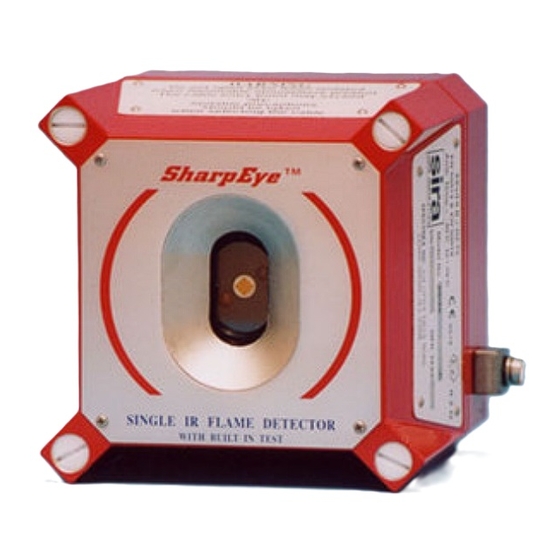
Single IR Flame Detector
User and Maintenance Manual
218 Little Falls Rd., Cedar Grove, NJ 07009 USA;
Phone: +1 (973) 239 8398 Fax: +1 (973) 239 7614
Web -Site:
www.spectrex-inc.com
Model 20/20R
TM 20/20R, Rev. A January 2005
ATEX Approved
Ex II 2G
EExd IIB + H
2
EExde IIB + H
; Email:
T5
T5
2
spectrex@spectrex-inc.com
Advertisement
Table of Contents

Subscribe to Our Youtube Channel
Related Manuals for Spectrex SharpEye 20/20R


Summary of Contents for Spectrex SharpEye 20/20R
- Page 1 TM 20/20R, Rev. A January 2005 ATEX Approved Ex II 2G EExd IIB + H EExde IIB + H 218 Little Falls Rd., Cedar Grove, NJ 07009 USA; Phone: +1 (973) 239 8398 Fax: +1 (973) 239 7614 Web -Site: www.spectrex-inc.com ; Email: spectrex@spectrex-inc.com...
- Page 3 The information in this document has been carefully checked and is believed to be entirely reliable with all of the necessary information included. Spectrex Inc. reserves the right to make changes to any products described herein to improve reliability, function, or...
-
Page 5: Table Of Contents
Spectrex Inc. - SharpEye Single IR Flame Detector Manual – TM 20/20R, Rev. A January2005 ABLE OF CONTENTS 1. Scope ...........................1 1.1 P ....................1 RODUCT VERVIEW 1.2 D ....................1 OCUMENT VERVIEW 2. Technical Description ...................2 2.1 P ..................2 RINCIPLE S PERATION 3. - Page 6 Spectrex Inc. - SharpEye Single IR Flame Detector Manual – TM 20/20R, Rev. A January2005 8.1 S ........................36 COPE 8.2 M ..........36 AINTENANCE INSTRUMENTATION AND ERSONNEL 8.3 P ............36 REVENTIVE AINTENANCE ROCEDURES 8.4 P ..............36 ERIODIC AINTENANCE ROCEDURES 8.4.1 Power-Up Procedure ...................36 8.4.2 Functional Test Procedure................36...
- Page 7 Spectrex Inc. - SharpEye Single IR Flame Detector Manual – TM 20/20R, Rev. A January2005 IGURES Figure 1: IR Flame Detector ....................2 Figure 2: Flame Detector Assembly - Outline Drawing ............ 3 Figure 3: Horizontal and Vertical Fields of View.............. 6 Figure 4: Indication LEDs ....................
- Page 8 Spectrex Inc. - SharpEye Single IR Flame Detector Manual – TM 20/20R, Rev. A January2005...
-
Page 9: Scope
1. Scope 1.1 Product Overview The Spectrex Model 20/20R Single IR Flame Detector provides early warning of flaming fires involving organic (hydrocarbon fuels and vapours) materials. These fires emit strong IR radiation in the 4.4-micron spectral band where the CO (main combustion product of any organic substance) has a unique spectral peak. -
Page 10: Technical Description
Spectrex Inc. - SharpEye Single IR Flame Detector Manual – TM 20/20R, Rev. A January2005 2. Technical Description • Detection Range: up to 50ft (15m) for a 1ft x 1ft (0.3m x 0.3m) fire. • Field Programmable Sensitivity: two ranges. -
Page 11: Figure 2: Flame Detector Assembly - Outline Drawing
Spectrex Inc. - SharpEye Single IR Flame Detector Manual – TM 20/20R, Rev. A January2005 Figure 2: Flame Detector Assembly - Outline Drawing... -
Page 12: Performance
Spectrex Inc. - SharpEye Single IR Flame Detector Manual – TM 20/20R, Rev. A January2005 3. Performance 3.1 Detection Sensitivity Detection sensitivity is the maximum distance at which the detector will reliably detect a specific size of fire & typical type of fuel (standard fire). -
Page 13: Table 2: Response Sensitivity Ranges
Spectrex Inc. - SharpEye Single IR Flame Detector Manual – TM 20/20R, Rev. A January2005 Other fuels The detector will react to other types of fires as follows: Pan Fire Size: 1ft x 1ft (0.3m x 0.3m) Maximum Wind Speed: 6.5 ft/sec (2 m/sec) -
Page 14: Cone Of Vision
Spectrex Inc. - SharpEye Single IR Flame Detector Manual – TM 20/20R, Rev. A January2005 3.2 Cone Of Vision Horizontal: 90° Vertical: 90° Figure 3: Horizontal and Vertical Fields of View... -
Page 15: False Alarms Prevention
Spectrex Inc. - SharpEye Single IR Flame Detector Manual – TM 20/20R, Rev. A January2005 3.3 False Alarms Prevention The detector will not provide an alarm or a warning signal as a reaction to the radiation sources specified below. Notes: IAD = Immune at Any Distance. -
Page 16: Operation
Spectrex Inc. - SharpEye Single IR Flame Detector Manual – TM 20/20R, Rev. A January2005 4. Operation 4.1 Visual Indications Two LED-indications are located in the detector front window: Power LED (Yellow) Normal - LED ON BIT failure - LED flashes (4 Hz) ii. -
Page 17: Output Signals
Spectrex Inc. - SharpEye Single IR Flame Detector Manual – TM 20/20R, Rev. A January2005 4.2 Output Signals The detector controls the following outputs: • Alarm relay • Accessory relay • Fault relay • 4-20mA current output • RS-485 communication The detector can be in one of the following states. -
Page 18: Optional Latching
Spectrex Inc. - SharpEye Single IR Flame Detector Manual – TM 20/20R, Rev. A January2005 4.2.1 Optional latching The detector includes a latched alarm output capability, which operates according to the DIPswitch SW1-1 position. Upon the detection of a fire, the detection signal is latched until manually reset (disconnecting the power supply or performing a manual BIT). -
Page 19: Function Switch (Sw1)
Spectrex Inc. - SharpEye Single IR Flame Detector Manual – TM 20/20R, Rev. A January2005 4.3.1 Function switch (SW1): The user can select the desired mode of operation by means of this switch according to table 5: Table 5: Function Switch SW1... -
Page 20: Address Switch (Sw2) (Optional)
Spectrex Inc. - SharpEye Single IR Flame Detector Manual – TM 20/20R, Rev. A January2005 4.3.2 Address switch (SW2) (Optional): The address switch provides 64 alternative addresses that can be used with the RS-485 communication link. See tables 7 and 8. -
Page 21: Alarm Delay Switch (Sw3)
Spectrex Inc. - SharpEye Single IR Flame Detector Manual – TM 20/20R, Rev. A January2005 4.3.3 Alarm Delay switch (SW3): The detector is equipped with an Alarm Delay option, which provides programmable time delays of 0 to 30 seconds with eight (8) fixed settings at: 0, anti-flare, 3, 5, 10, 15, 20, and 30 seconds, using SW3 switches 1-3. -
Page 22: Built In Test
Spectrex Inc. - SharpEye Single IR Flame Detector Manual – TM 20/20R, Rev. A January2005 ANTI FLARE Anti Flare mode is selected to prevent false alarm in locations where fast flares may be present. The Time delay for fire alarm in this mode is from 2.5 to 15 seconds (mostly less than 10 seconds). - Page 23 Spectrex Inc. - SharpEye Single IR Flame Detector Manual – TM 20/20R, Rev. A January2005 B. Principles If the result of a BIT is the same as the detector’s current status (NORMAL or FAULT), the detector's status will not change.
- Page 24 Spectrex Inc. - SharpEye Single IR Flame Detector Manual – TM 20/20R, Rev. A January2005 D. Automatic & Manual BIT (SW1-3 = ON) Manual Bit Functions as described in Para. 4.4.c. In the case of an unsuccessful BIT all outputs will function as described in para. 4.4.c, but the BIT will be automatically executed every 1-minute.
-
Page 25: Technical Specifications
Spectrex Inc. - SharpEye Single IR Flame Detector Manual – TM 20/20R, Rev. A January2005 5.Technical Specifications 5.1 Electrical Specifications A. Operating Voltage: 18-32 VDC B. Power Consumption: Max. 150mA in Stand-by Max. 200mA in Alarm C. Electric input protection: The input circuit is protected against voltage- reversed polarity, voltage transients, surges and spikes according to MIL- STD-1275A. -
Page 26: Figure 6: Electrical Interface
Spectrex Inc. - SharpEye Single IR Flame Detector Manual – TM 20/20R, Rev. A January2005 D. Terminals: Figure 6: Electrical Interface... -
Page 27: Figure 7: Flame Detector Assembly - Schematic Section
Spectrex Inc. - SharpEye Single IR Flame Detector Manual – TM 20/20R, Rev. A January2005 E. Electrical outputs • Dry Contact Relays: Table 10: Contact Ratings Relay Type Normal Maximum Ratings Name position Alarm SPDT N.O. N.C. 2A at 30VDC or 0.5A at 250 VAC Accessory SPST N.O. -
Page 28: Mechanical Specifications
Spectrex Inc. - SharpEye Single IR Flame Detector Manual – TM 20/20R, Rev. A January2005 5.2 Mechanical Specifications A. Enclosure Aluminum: Chromate coating and Epoxy enamel finish Stainless Steel 316: Electrochemical passivated coating B. Explosion proof ATEX Ex II 2G SIRA 00ATEX 1163, 1164 EExd IIB + H Temp. -
Page 29: Environmental Specifications
Spectrex Inc. - SharpEye Single IR Flame Detector Manual – TM 20/20R, Rev. A January2005 5.3 Environmental Specifications A. High Temperature Design to meet MIL-STD-810C, method 501.1 procedure II Operating temperature: +160 °F (+70 °C) Optional operating temperature: +185 °F (+85 °C) Storage temperature: +185 °F (+85 °C) -
Page 30: Installation Instructions
6. Installation Instructions 6.1 Scope The "Spectrex" Model 20/20R is a self-contained Optical Flame Detector, designed to operate as a stand-alone unit directly connected to alarm systems or automatic fire extinguishing systems. The detector can form part of a more complex system where many detectors and other devices are integrated through a common control unit. -
Page 31: Preparations For Installation
Spectrex Inc. - SharpEye Single IR Flame Detector Manual – TM 20/20R, Rev. A January2005 6.3 Preparations for Installation Installation should comply with NFPA 72E, as applicable to flame detectors, where required. The detectors can be installed with the use of general-purpose common tools and equipment. -
Page 32: Detector Mounting
Spectrex Inc. - SharpEye Single IR Flame Detector Manual – TM 20/20R, Rev. A January2005 6.5 Detector Mounting The detector may be mounted on a simple fabricated bracket, or preferably the optional Swivel Mount, Model 20/20-003. The Swivel Mount enables the detector to be rotated up to 40 degrees in all directions. -
Page 33: Figure 8: Ir Detector And Swivel Mount Assembly
Spectrex Inc. - SharpEye Single IR Flame Detector Manual – TM 20/20R, Rev. A January2005 Figure 8: IR Detector and Swivel Mount Assembly... -
Page 34: Figure 9: Swivel Mount Assembly - Outline Drawing
Spectrex Inc. - SharpEye Single IR Flame Detector Manual – TM 20/20R, Rev. A January2005 Description Protective Set Screws Ground Terminal (for ATEX) or Ground Thread (for FM) Back Cover Housing Swivel Mount Screw Hole Swivel Mount Holding Plate Locking Screws... -
Page 35: Wiring (Refer To Fig. 12)
Spectrex Inc. - SharpEye Single IR Flame Detector Manual – TM 20/20R, Rev. A January2005 6.6 Wiring (Refer to Fig. 12) 1 Disconnect power. 2 Remove the four (4) protective set-screws from detector front. (Fig. 8 Item 1) 3 Release the four (4) socket-head screws that secure the detector housing (Item 1) to its back cover (Item 5) Using HEX KEY No. -
Page 36: Terminal Wiring (See Fig. No.10 And No.11.)
Spectrex Inc. - SharpEye Single IR Flame Detector Manual – TM 20/20R, Rev. A January2005 6.7 Terminal wiring (See Fig. No.10 and No.11.) The detector contains a Terminal Board consisting of two (2) terminal blocks (Item 4). The left terminal block is labeled 1 to 7, the right terminal block is labeled 8 to... -
Page 37: Figure 10: Terminal Board
Spectrex Inc. - SharpEye Single IR Flame Detector Manual – TM 20/20R, Rev. A January2005 • 4-20mA Output (Terminal Numbers 11, 12): Terminal Numbers 11 and 12 are used for analog, 4-20mA current output as specified in paragraph 4.e Terminal No. 11 - output Terminal. -
Page 38: Figure 11: Flame Detector Assembly - Wiring Diagram
Spectrex Inc. - SharpEye Single IR Flame Detector Manual – TM 20/20R, Rev. A January2005 Figure 11: Flame Detector Assembly - Wiring Diagram... -
Page 39: Figure 12: Ir Flame Detector With Cover Removed
Spectrex Inc. - SharpEye Single IR Flame Detector Manual – TM 20/20R, Rev. A January2005 Description Housing Securing Cable Cable Clamp Terminal Board Back Cover Inlet Conduit DIP Switch1 DIP Switch2 DIP Switch3 Figure 12: IR Flame Detector with cover removed... -
Page 40: Mode Selection
Spectrex Inc. - SharpEye Single IR Flame Detector Manual – TM 20/20R, Rev. A January2005 6.8 Mode Selection When wiring is completed the operational mode can be selected. Mode selection is achieved by means of 3 DIPswitches listed below: SW1 - Function switch – Fig. 12 Item 7 (see table 6) SW2 - Address switch –... -
Page 41: Operating Instructions
ALARM state, is achieved by disconnecting power (terminal No. 1 or terminal No. 2), or initiation of a manual BIT. 7.4 Functional testing Following is a test procedure for proper functioning of the detector. The detector can be tested using the Manual Built-in-Test or the Spectrex IR Fire Simulator - 20/20-312... -
Page 42: Manual Bit Test
Power LED turns on. If the detector is on, skip this step. Aim the Spectrex Fire Simulator Model 20/20-312 to the target point of the detector (see Fig. 22), in a way that the radiation emitted by it is facing directly towards the detector. -
Page 43: Safety Precautions
Spectrex Inc. - SharpEye Single IR Flame Detector Manual – TM 20/20R, Rev. A January2005 7.5 Safety Precautions After Powering-up, the detector requires hardly any attention in order to function properly, but the following should be noted: 1 Follow the instructions in the manual and refer to the drawings and specifications issued by the manufacturer. -
Page 44: Maintenance Instructions
Spectrex Inc. - SharpEye Single IR Flame Detector Manual – TM 20/20R, Rev. A January2005 8. Maintenance Instructions 8.1 Scope This chapter deals with preventive maintenance, describes possible faults in detector operation and indicates corrective measures. Ignoring these instructions may cause problems with the detector and may invalidate the warranty. Whenever a unit requires service, please contact the manufacturer or its authorized distributor for assistance. -
Page 45: Maintenance Records
Spectrex Inc. - SharpEye Single IR Flame Detector Manual – TM 20/20R, Rev. A January2005 8.5 Maintenance Records It is recommended to record maintenance operations performed on a detector in a system Log-book. The record should include information, which identifies the unit, the installation date, contractor, and entries for every maintenance operation performed including the description of the operation, date and personnel ID. - Page 46 Spectrex Inc. - SharpEye Single IR Flame Detector Manual – TM 20/20R, Rev. A January2005...
-
Page 47: Appendix A - Wire Selection Tables
Spectrex Inc. - SharpEye Single IR Flame Detector Manual – TM 20/20R, Rev. A January2005 Appendix A - Wire Selection Tables General Instructions For Electrical Wiring 1. Refer to Table 13 to determine the required wire gauge for general wiring, such as relay wiring. - Page 48 Spectrex Inc. - SharpEye Single IR Flame Detector Manual – TM 20/20R, Rev. A January2005...
-
Page 49: Appendix B - Typical Wiring Configurations
Spectrex Inc. - SharpEye Single IR Flame Detector Manual – TM 20/20R, Rev. A January2005 Appendix B – Typical Wiring Configurations Figure 13: Flame Detector Wiring Diagram... -
Page 50: Figure 14: Typical Wiring Diagram For 4 Wire Controllers
Spectrex Inc. - SharpEye Single IR Flame Detector Manual – TM 20/20R, Rev. A January2005 Figure 14: Typical wiring diagram for 4 wire controllers... -
Page 51: Figure 15: Typical Wiring Diagram For Controllers With Alarm & Fault Loops
Spectrex Inc. - SharpEye Single IR Flame Detector Manual – TM 20/20R, Rev. A January2005 Figure 15: Typical wiring diagram for controllers with alarm & fault loops Notes: 1. For EOL Resistors Values See Controller Manual 2. The Accessory Relay in The Last Detector Should be Configured as an EOL... -
Page 52: Figure 16: 4-20Ma Wiring
Spectrex Inc. - SharpEye Single IR Flame Detector Manual – TM 20/20R, Rev. A January2005 Figure 16: 4-20mA wiring Notes: The detectors are factory set to isolated 4-20mA ‘sink’ version. To work at non-isolated 4-20mA version (“source”), connect Terminal 12 to... -
Page 53: Appendix C - Rs-485 Communication Network
Spectrex Inc. - SharpEye Single IR Flame Detector Manual – TM 20/20R, Rev. A January2005 Appendix C – RS-485 Communication Network Using the RS-485 network capability of the IR detector and additional software it is possible to connect up to 32 detectors in an addressable system with 4 wires only (2 for power &... - Page 54 Spectrex Inc. - SharpEye Single IR Flame Detector Manual – TM 20/20R, Rev. A January2005...
-
Page 55: Appendix D - Mounting The "Eexde Approved" Version
Spectrex Inc. - SharpEye Single IR Flame Detector Manual – TM 20/20R, Rev. A January2005 Appendix D - Mounting the “EExde approved” version The EExde approved version provides an additional EExe terminal box attached below the EExd detector and therefore allows easier access for wiring in difficult environments and hazardous areas (see fig. - Page 56 Spectrex Inc. - SharpEye Single IR Flame Detector Manual – TM 20/20R, Rev. A January2005 2. W . 18.) IRING EFER TO Disconnect power. Release the four (4) slotted-head screws (item 3) that secure the chamber cover (Item 2). The chamber is now revealed.
-
Page 57: Figure 18: Flame Detector Assembly - Wiring Diagram
Spectrex Inc. - SharpEye Single IR Flame Detector Manual – TM 20/20R, Rev. A January2005 Figure 18: Flame Detector Assembly - Wiring Diagram Description 1. Modified Back Cover 5. Ground Terminal 2. EExe Chamber Cover 6. Mounting Thread 3. Slotted Screw 7. -
Page 58: Figure 19: Option A Flame Detector Assembly - Wiring Diagram ("De Version")
Spectrex Inc. - SharpEye Single IR Flame Detector Manual – TM 20/20R, Rev. A January2005 2.1 Terminal Wiring The detector contains an EExe chamber consisting of a terminal block (Item 4). The terminal block is labeled 1 to 6. (See Fig. No.18) -
Page 59: Appendix E - Ir Fire Simulator
Spectrex Inc. - SharpEye Single IR Flame Detector Manual – TM 20/20R, Rev. A January2005 Appendix E - IR Fire Simulator Figure 21: Fire Simulator Product Description The SharpEye IR Long Range Fire simulator 20/20-312 is designed specifically for use with the IR flame detectors. The Fire Simulator emits IR radiation in a unique sequential pattern corresponding and recognizable by the IR detector as fire. -
Page 60: Figure 22: Ir Detector Target Point
Spectrex Inc. - SharpEye Single IR Flame Detector Manual – TM 20/20R, Rev. A January2005 Figure 22: IR Detector Target Point Follow these instructions to simulate a fire: 1. Aim the Fire Simulator towards the detector’s “Target Point”. 2. For testing keep a distance of at least 20 inches (50cm) from the detector. - Page 61 Spectrex Inc. - SharpEye Single IR Flame Detector Manual – TM 20/20R, Rev. A January2005 Specifications Mechanical Explosion Proof Enclosure: NFPA (designed to meet) Class I, Division 1 & 2 Groups B, C and D Class II, Division 1 & 2 Groups E, F, and G ATEX (designed to meet) EX II2G EExd IIB T5 50 C per En 50-014 &...
- Page 62 Spectrex Inc. - SharpEye Single IR Flame Detector Manual – TM 20/20R, Rev. A January2005 For additional details or assistance, please contact 218 Little Falls Road Cedar Grove, NJ 07009, USA Tel: (973) 239-8398 Fax: (973) 239-7614 Email: spectrex@spectrex-inc.com Web-site: www.spectrex-inc.com...
Need help?
Do you have a question about the SharpEye 20/20R and is the answer not in the manual?
Questions and answers