Siemens ST950 Plus+ User Manual
Hide thumbs
Also See for ST950 Plus+:
- Handbook (154 pages) ,
- Installation method statement (14 pages) ,
- Handbook (125 pages)
Table of Contents
Advertisement
Quick Links
Advertisement
Table of Contents

Subscribe to Our Youtube Channel
Related Manuals for Siemens ST950 Plus+


Summary of Contents for Siemens ST950 Plus+
- Page 1 Plus+ ST950 Plus+ User Manual Issue 6 Issue 2 Sept-19 Apr-21 667/HE/53000/000...
-
Page 2: Change History
First Issue Siemens Apr 2021 Updates and corrections Siemens The electronic version of this handbook can be found on the Siemens website www.siemens.co.uk/traffic in the Handbooks section under Downloads. SAFETY INFORMATION General Hazards IT IS RECOMMENDED THAT DUE TO THE MAINS PRESENT WITHIN THE CONTROLLER CABINET ALL POWER TO THE CABINET IS DISCONNECTED BEFORE REMOVING OR INSTALLING ANY MAINS POWERED EQUIPMENT INTO THE CABINET. - Page 3 Equipment Compatibility Do not connect any device that has not been specifically designed or evaluated for compatibility with the ST950 Plus system. If in doubt, contact Siemens Mobility Limited for further information. ST950 Plus compatible equipment such as Helios Plus...
- Page 4 ST950 Plus+ User Manual Safety of Road Users It is important that all personnel are aware of the dangers to road users that could arise during repair and maintenance of traffic control equipment. Ensure that appropriate traffic management and is signed at the junction area to warn motorists and pedestrians of any dangers and to help protect the personnel working on the site.
- Page 5 ST950 Plus+ User Manual Important Plus Considerations To provide the most reliable operation, the Siemens ST950 Plus controllers use a DC supply. To maintain all street voltages within ELV limits, equipment outside the cabinet must be supplied with voltages within the band 0 to +48V DC with respect to earth. Voltages beyond that will result in overall voltages within the system being in excess of the ELV limit as defined by BS7671.
-
Page 6: Table Of Contents
ST950 Plus+ User Manual Contents Change History ........................2 SAFETY INFORMATION ....................... 2 Introduction ........................8 Purpose ........................8 Contact Us ......................8 Reference Documents ..................... 8 Pre-Requisites ......................9 Definitions ......................11 Abbreviations ....................... 11 Third Party Information ..................13 Trademarks ...................... - Page 7 ST950 Plus+ User Manual Connection ......................99 Types of User Interface ..................99 Installation and Commissioning Procedure ..............101 Service-Centre Cabinet Testing ................101 Checking Site Suitability ..................102 Cabinet Installation - Summary ................103 Installation of Stool ..................... 104 Installation of Traffic Signal Poles.
-
Page 8: Introduction
Ongoing development means that some of the delivered items may differ in detail from the photographs included in this handbook. Contact Us If you have any comments on this handbook, or need any further information, you can contact us at support.ts.uk.mobility@siemens.com. Reference Documents 1.3.1 Controller (Essential) -
Page 9: Pre-Requisites
ST950 Plus+ User Manual 1.3.3 Installation and Commissioning Publisher Reference Number Document Title 667/HQ/53000/300 ST950 Plus Installation App Quick Start Guide 667/HE/20662/000 Installation & Commissioning – Signals & Poles 667/HB/30000/000 Helios General Handbook 667/HB/31900/000 Heimdall Above Ground User Manual 667/HB/45200/000 SLD4 Loop Detector Handbook 667/HE/20663/000 Loop Detector and Cable Terminations –... - Page 10 ST950 Plus+ User Manual 1.4.2 Required Tools In addition to a standard Engineer’s tool kit, the following tools are required when carrying out any work on the ST950 family of controllers. User Interface One of the following is required depending on the user interface chosen to be used during the installation.
-
Page 11: Definitions
Controller identification number (ElectroMatic). Configuration Identity Code (equivalent to EM above) Generic Versatile Platform - used by ST950 and other Siemens products to provide general services such as comms, user interface, etc. A scale drawing of the intersection including controller position, detector loop... - Page 12 ST950 Plus+ User Manual Abbreviation Meaning HTTP Hypertext Transfer Protocol HTTPS HTTP Secure Intersection Configurator v.4 (UK controller configuration application) Intelligent Detector Backplane Input/Output Intelligent Traffic Systems Kit of Parts Light Emitting Diode Lamp Monitoring Unit Logic Power Unit LSLS Lamp Switch Low-Voltage Serial Network Time Protocol OCSP...
-
Page 13: Third Party Information
Generally, these embedded free software files are distributed in the hope that they will be useful, but WITHOUT ANY WARRANTY, without even implied warranty such as for MERCHANTABILITY or FITNESS FOR A PARTICULAR PURPOSE, and without liability for any Siemens entity other than as explicitly documented in your purchase contract. -
Page 14: Plus + Introduction And Basic Principles
ST950 Plus+ User Manual NTRODUCTION AND ASIC RINCIPLES The Siemens ST950 Plus system is part of the wider ST950 family of controllers and associated equipment. The ST950 Plus system will run very similar firmware and offers same facilities as the rest of the ST950 family, including license enabled integral MOVA8 and integral UTMC OTU facilities. - Page 15 ST950 Plus+ User Manual Figure 2 – System Overview On the street, the armoured street cables terminate at a “Pole Top Board” (PTB) within the Traffic Signal Pole, located inside the Pole Cap. An option for mid-level or low-level access poles is also available (using a 16-way protected terminal block assembly, 667/1/58200/026).
-
Page 16: Plus+ System Components: An Overview
ST950 Plus+ User Manual Plus+ System Components: An Overview 2.1.1 ST950 CPU Card The CPU Card performs all high-level control functions for the junction and communicates with the peripheral I/O cards and CIC cards using high speed serial communication protocols. The physical interfaces are the same as those used in the existing ST950 family of controllers. - Page 17 ST950 Plus+ User Manual • CPUA and CPUB microprocessors • EEPROM / FRAM for inventory, identification and fault information • Lightning protection for the RS485 ring/arm interfaces • Diagnostic LEDs Reference section 3.16 for further information. 2.1.3 Nodes and Bypass Module An example of a Node is the RAG Node.
- Page 18 ST950 Plus+ User Manual The RAG Node is provided with a cover to give some mechanical protection and has several status LEDs. which indicate the operational status of the Node. The RAG Node PCB is conformally coated to provide additional protection and improve reliability. A Bypass Module is included which plugs into the RAG Node.
-
Page 19: The Principles Of Plus + Wiring
ST950 Plus+ User Manual 2.1.4 Smartloop Modules The Smartloop unit is a combination of a node and an SLD4. The combination of these devices, developed as a single PCB, is housed in a plastic enclosure and then fully potted. The Smartloop device can then be connected to the Plus+ network and provide an interface for inductive traffic detection loops. - Page 20 ST950 Plus+ User Manual Street Cable (Return to make Ring) Bypass/PDU (Stubby) Pole Top Pole Top Pole Top Termination Termination Termination Board Board Board Bypass/RAG Bypass/RAG Bypass/Nearside Node Node Street Cable Dropper Cable Bypass/PDU +48VDC +48VDC Smartloop D+ (back to pole top) D- (back to pole top) Figure 4 : Principles of Plus Wiring...
- Page 21 ST950 Plus+ User Manual Figure 5 : Stub Pole Wiring Arrangements 2.2.4 Smartloop Wiring Options The Smartloop can be wired in a number of different arrangements depending on the design/topology. The following diagrams are examples of possible installation configurations. Loop Feeder Cable Cable Joint...
- Page 22 ST950 Plus+ User Manual Cable Cable Cable joint joint joint Plus+ Street Cable From RAG Node Loop Feeder Cable Cable joint Joint Plus+ Street Cable From upstream Smartloop Plus+ Loops Plus+ Loops SmartLoop SmartLoop Figure 7 : Smartloop Layout Example 2 : VA Note: Unlike other Plus+ Nodes the Smartloop has no Bypass Module.
-
Page 23: Configuration
Design Layout Configuration now provides the link between the IC4 configuration and the junction layout as designed – as opposed to wiring in a Lamp Switch Card. Siemens Mobility has developed the Plus Design Layout Tool, which works hand in hand with KeySignals (KeySoft product). - Page 24 ST950 Plus+ User Manual The Plus+ Design Layout Tool exposes the features, within KeySignals, such as Traffic Phases and Detection naming, that is referenced by the controller when defined by IC4. AutoCad Design Layout Tool (KeySignals) Layout Design Layout Drawing (*.pdf) Configuration (*.zip) Installation App...
-
Page 25: Plus + : Key Considerations
ST950 Plus+ User Manual Plus+ STS drawing On completion of a Traffic Junction Design (STS Drawing) the Plus+ Design Layout Tool will be used to generate the Plus+ Design Layout Configuration. This configuration can either be imported directly to a controller or passed to the Plus+ Installation App. The STS drawing contains all the pertinent information for on- street cable connections and should be referred to accordingly. - Page 26 ST950 Plus+ User Manual This warning occurs when, in the LMU General screen, a customer has “RLF2 only cleared by RFL=1” ticked on this screen. This warning has been added because the Plus+ Controller may trigger RLM faults during some power and/or communications scenarios.
-
Page 27: St950 Plus Controller Cabinet
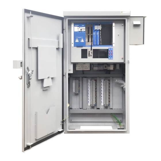
ST950 Plus+ User Manual ST950 P ONTROLLER ABINET This section details the main elements, of the ST950 Plus system, that are held within the controller cabinet. The Primary Plus Controller Cabinet Figure 12 and Figure 13 below show the ST950 Plus controller CPU card fitted in a standard ST950 Controller Cabinet. - Page 28 ST950 Plus+ User Manual I/O Card I/O Card Manual Panel Manual Panel CIC/CTB Card CIC/CTB Card SLD4 SLD4 Detectors Detectors Cards Cards ST950 CPU Gemini Outstation Unit Switch Panel Master Switch 48V PSU 48V PSU Panel On-Street On-Street Plus+ Plus+ Cable Cable Loop Feeder Cable...
-
Page 29: The Controller Rack
ST950 Plus+ User Manual The Controller Rack Figure 13, below, shows the ST950 Plus controller in a 6U 19" rack. The 19” Controller Rack is sub-divided into one 6U-high bay and two 3U-high bays. The 6U bay is fitted with the CPU Card. The arrangement of the rear panel and the rack allows for a number of I/O card or detector options to be provided: •... -
Page 30: Cabinet Stool Options
As standard the Plus cabinet is not supplied with a stool pre-assembled. Instead the customer may select from a number of stool options namely; ST950 Plus Stool, standard Siemens Stool or NAL stool. Please refer to Section 6.4 for more information. Stool Type... -
Page 31: Master Switch Panel
ST950 Plus+ User Manual Master Switch Panel The Master Switch Unit, which comprises the switch gear and some monitoring elements, for all the incoming mains and the Power Bank. The Power Bank is comprised of the 48VPSUs and Redundancy Module(s). There are two variants of the Master Switch Panel, in order to suit a standard or a Hi-load build configuration. - Page 32 ST950 Plus+ User Manual MCB 16C Master Fuse 32A Figure 15 : Master Switch Unit – Hi-Load The selection of Standard or Hi-Load will depend on the controller loading. However, the selection of the MSP is automatically made by the Plus Design Layout Tool.
-
Page 33: 24V Psu
ST950 Plus+ User Manual 24V PSU The 24V PSU is a DIN rail mounted 100W device. The 24V PSU is used to provide the supply for the ST950 CPU and the logic supply for the CIC(s). In addition, the 24VPSU is used to provide power to auxiliary equipment such as I/O cards, including the IDB. -
Page 34: Redundancy Module
ST950 Plus+ User Manual In order to ensure high reliability, the Plus system includes power supply redundancy, see below, so that failure of one 48V PSU will not extinguish the signals, improving the availability of the Traffic Signals. An additional advantage is that the 48V PSU can, individually, be swapped out without impacting junction running. - Page 35 Table 3 – I/O Card LEDs PSUs are factory adjusted and should not give a voltage imbalance. If it occurs, solving an Imbalance issue involves the careful adjustment of the connected PSUs. Please contact Siemens Engineering in Poole for assistance before attempting any adjustment.
-
Page 36: St950 Plus + Cpu Card
ST950 Plus+ User Manual ST950 Plus CPU Card The CPU card for Plus is common with that used for LV and ELV versions of the ST950. There are two variants of the CPU card which differ only in the amount of RAM available on the EFC module. For Plus , only the 128M RAM variant is appropriate. - Page 37 ST950 Plus+ User Manual LICENCE HEART Smart RJ45 LSLS Card SD Card RJ45 SITE SPECIFIC RJ45 RJ45 Coin Serial Cell Manual Panel Host LEVEL3 Host LOCAL USB EFC USB Type B RJ45 FLASH 10/100 Ethernet DB25 Handset Handset RESET Fuse 500mA Quick Blow Figure 19 –...
- Page 38 ST950 Plus+ User Manual Description Connector Serial Phase bus to CTB RJ45 GSPI Bus to CTB RJ45 GSPI Bus to I/O Cards (SIO) or other GSPI RJ45 peripherals GSPI Manual Panel (PANEL) [Future Use] RJ45 Cabinet Signals (Top) Double stacked 10 way IDC Auxiliary RS232 Connection (Bottom) Refer to Table 2 for pinout Rear USB Host Port...
- Page 39 ST950 Plus+ User Manual Flashes in a heartbeat pattern Primary CPU software is operating normally Flashes slowly (once per second) Controller self test Flashes quickly (several times per second) Non normal operation e.g. start-up SE - System Error (red) Permanently on Fault is present, e.g.
- Page 40 ST950 Plus+ User Manual Not under UTC control, pulses on indicate receipt of messages BSY – Busy (red) Flashes to indicate the system is busy performing an operation that must not be interrupted, for example start up, upgrade, USB "memory stick" style interface is busy. Do not remove USB device or switch off the controller while this LED is flashing.
- Page 41 ST950 Plus+ User Manual Location Function Door switch return (0V) Reset fault log button input signal Reset fault log button return (0V) Bottom +5V Fused (500mA) RS232 DSR (Input) RS232 RxD (Input) RS232 RTS (Output) RS232 TxD (Output) RS232 CTS (Input) RS232 DTR (Output) Not Used Not Used...
- Page 42 ST950 Plus+ User Manual Location Function External supply monitor signal return (0V) External supply monitor signal (analog) External supply monitor signal return (0V) Bottom RS232 DCD (Input) RS232 DSR (Input) RS232 RxD (Input) RS232 RTS (Output) RS232 TxD (Output) RS232 CTS (Input) RS232 DTR (Output) RS232 RI (Input) Not Used...
- Page 43 ST950 Plus+ User Manual – Figure 20 - Double stacked connector pin numbering 3.8.4 Links, Switches and Fuses Before the controller is switched on, the switches and links on the CPU Card must be checked to ensure they are set correctly. Also, the firmware should be checked to ensure that the correct version (as specified on the IC4 printout) is loaded.
-
Page 44: Fuses
F2 – Aux RS232 Modem power supply output – 500mA Quick blow The replacement fuse for F1 and F2 is Siemens part number 518/4/97070/004. This part number calls up the holder and fuse. Remove the fuse and discard the holder. -
Page 45: Gemini3 (Stratos Outstation)
ST950 Plus+ User Manual Figure 21 : SD card Write Enable switch position Figure 22 : SD Card Orientation SD card partially inserted - incorrect SD card fully inserted - correct ✓ Gemini3 (Stratos Outstation) For information regarding the Gemini3 equipment, see: 667/HB/52250/000 - Stratos Outstation Handbook ST950 Plus+ User Manual Page 45 of 176... -
Page 46: 3.12.2 Panel Mounted I/O Cards
ST950 Plus+ User Manual Panel Mounted I/O Cards 3.12.1 Overview The need to use I/O cards in a Plus system is much reduced since most I/O functionality is performed by the Nodes directly. However, the standard ST950 I/O cards are supported for cases where centrally located I/O is required, for example to support a free standing OTU or MOVA unit. - Page 47 ST950 Plus+ User Manual Inputs 0-11 Inputs 12-23 Common Common Return for Return for Inputs Inputs Outputs 0-3 Outputs 8-11 Outputs 4-7 Outputs 12-15 Figure 23 – I/O Card (Showing 16-output variant) GSPI comms input Status LEDs GSPI comms Address from Processor Card output to next switch...
- Page 48 ST950 Plus+ User Manual 3.12.3 I/O Card Status LEDs The I/O card has three tri-colour status LEDs as shown in Figure 24, which are used to indicate various conditions , as follows: Comms Active Software Run LED Watchdog LED State LED (LP1) (LP2) (LP3)
-
Page 49: Cpu I/O Card
ST950 Plus+ User Manual CPU I/O Card The CPU I/O card is designed to provide an ‘integrated’ I/O capability for ‘smaller’ controllers. The card is mounted onto the CPU Card as shown below and provides 24 inputs and 4 changeover outputs. - Page 50 ST950 Plus+ User Manual Top Row Bottom Row Output 1 Common Input 1 Connected to Pin 1 Input 2 Output 1 Normally Open Input 3 Output 1 Normally Closed Input 4 N.C. Input 5 N.C. Input 6 Output 2 Common Input 7 Connected to Pin 7 Input 8...
-
Page 51: Intelligent Detector Backplane Card
Intelligent Detector Backplane Card The Intelligent Detector Backplanes (IDB) are mounted within the rack. Each IDB provide support for the connection of up to 4 Loop Detector Cards, such as Siemens SLD4 or the WiMag Loop Replacement Card. The IDB connects via a ribbon cable to the Loop Termination Board mounted on the cabinet rear panel. - Page 52 ST950 Plus+ User Manual GSPI comms IN from GSPI comms Processsor or OUT to next Address previous IDB Switch Input 24V DC- /AC Input 24V DC+ /AC Output 24V DC- /AC Output 24V DC+ /AC Twist and Flat Ribbon Cable to Loop Termination Board Figure 26 –...
- Page 53 ST950 Plus+ User Manual 3.14.1 Intelligent Detector Backplane Card LEDs The Intelligent Detector Backplane Card has three tri-colour status LEDs which are identical to the LEDs on the I/O card as described in section 3.13 above. It should be noted that these LEDs are viewed from above and are seen in reverse order (i.e.
- Page 54 ST950 Plus+ User Manual 3.14.3 Loop Detector Power The power for the Loop Detector cards is taken from the 24VDC PSU. See Figure 27 for the power connections on the Intelligent Detector Backplane. If additional Intelligent Detector Backplanes are required, then the 24VDC can be daisy chained from the first IDB.
-
Page 55: Loop Detector Cards
ST950 Plus+ User Manual Loop Detector Cards The Loop Detector cards pick up the Loop Detector Power from SK7 on the Intelligent Detector Backplane Card in which they are plugged into. Further detailed information regarding Loop Detector Cards is available in the SLD4 Loop Detector Handbook (667/HB/45200/000). -
Page 56: Cic Card And Ctb (Backplane)
ST950 Plus+ User Manual CIC Card and CTB (Backplane) 3.16.1 Overview The CIC is the Plus communications hub and provides controller power distribution for the remote nodes, via the street wiring. Its main role is to provide safe communications to remote nodes such as RAG, Wait and Nearside nodes in order to control the traffic signalling. - Page 57 ST950 Plus+ User Manual Street wiring is terminated directly to the CTB via cage clamp terminal blocks. The CTB in turn routes its connected signals to the CIC via DIN standard connectors. The CIC is fitted with a metallic cover to provide a degree of protection from accidental contact. However, there are no hazardous voltages present on the PCB.
- Page 58 ST950 Plus+ User Manual Figure 29 : CTB Terminations ST950 Plus+ User Manual Page 58 of 176 Issue 2 667/HE/53000/000 Unrestricted...
- Page 59 ST950 Plus+ User Manual 3.16.2 CIC/CTB Interfaces: Serial Phase Bus (SPB) The CIC/CTB has two SPB interfaces, SPB In and SPB Out. The SPB-IN connection for the first CIC/CTB in the system connects to the ST950 CPU. The SPB Out connects to the next CIC/CTB in the system via its SPB-IN connector.
- Page 60 ST950 Plus+ User Manual Figure 30 CTB Street Termination to Nodes Figure 31 CTB Street Termination Detail ST950 Plus+ User Manual Page 60 of 176 Issue 2 667/HE/53000/000 Unrestricted...
- Page 61 ST950 Plus+ User Manual Figure 31 shows the function of the terminals. The arrows are coloured to indicate the conductor colours of connected cables (in the above example two cables). The +48V and 0V carry power to the nodes, whereas the D+ and D- carry the RS485 data communications.
- Page 62 ST950 Plus+ User Manual 3.16.7 CIC/CTB Interfaces: Lamp Supply PL20 provides an optional connection to an Outstation Monitoring Unit (OMU), where the OMU can monitor whether the signals (Lamps) are on or off. The 24V output from the CIC/CTB will normally drive an external relay (e.g.
- Page 63 ST950 Plus+ User Manual 3.16.10 CIC/CTB Interfaces: ZXO Input The ZXO or Zero Crossing input is connected to the secondary of a toroidal transformer. The CIC processes the AC waveform from this transformer to produce timing signals where the AC waveform crosses 0V.
- Page 64 ST950 Plus+ User Manual 3.16.12 CIC/CTB Interfaces: Relay A and Relay B and Consolidated Relay Relay A and Relay B are signals from the ST950 CPU that in normal operation are asserted (pulled low). If the ST950 detects a major fault it may de-assert either Relay A or Relay B or both Relays. The first CIC/CTB in the system connects to the ST950 Relay A and Relay B via a 6- way Molex connector PL5.
- Page 65 ST950 Plus+ User Manual 3.16.14 CIC/CTB Status LEDs The status LEDs provide an engineer with some information on the correct operation of the CIC. The CIC has six LEDs (three per CPU) which are used to indicate various conditions as follows; Illumination Function LP1x –...
- Page 66 ST950 Plus+ User Manual 3.16.15 Parts ST950 CIC Card Assembly 667/1/53090/000 ST950 CTB Replacement 667/1/53170/001 ST950 CTB Assembly 667/1/53050/000 CTB cable kits for CIC position 2 667/1/53051/002 CTB cable kits for CIC position 3 667/1/53051/003 Additional Inrush Relay kit 667/1/53058/000 Used when additional CIC is being added to a controller (includes Redundancy Module) ST950 Plus+ User Manual Page 66 of 176...
-
Page 67: Manual Panel
The Manual Panel provides a direct means of manually controlling the junction in a safe manner. The panel cable connects directly to the CPU Card as shown in Figure 19. The full intersection manual panel is shown in Figure 33 below. SIGNALS CABINET ALARM SIEMENS MODE MANUAL CONTROLS SELECT NORMAL MANUAL... - Page 68 ST950 Plus+ User Manual 3.17.1 Manual Panel LEDs The LEDs on the Manual Panel are used to identify which stage is active and to display status. Several versions of the Manual Panel are available and some of the indicators in the following summary may not be present in all variants.
- Page 69 ST950 Plus+ User Manual 3.17.2 Signals On/Off Switch The lamp supply to the phase switch cards is removed immediately OFF is selected on the SIGNALS OFF/ON switch, extinguishing the signals. Safe Traffic Conditions Care should be taken to ensure safe traffic conditions before operating the switch. With the OFF position selected, normal microprocessor control operations continue, and the phase selections being implemented can be observed on the Lamp Switch indicators.
-
Page 70: St950 Plus + System Components : On Street
ST950 Plus+ User Manual ST950 P YSTEM OMPONENTS TREET This section details the main components of the ST950 Plus system that are mounted on-street (i.e. outside of the cabinet). Pole Top Board 4.1.1 Overview The Pole Top Board is used to ensure a quick and uncomplicated way of wiring to and from a range of nodes held on traffic poles. - Page 71 ST950 Plus+ User Manual Street cable to the Street cable from next Pole Top cabinet or from (downstream) upstream Pole Top Termination Board. Figure 35 : PTB with 4 Way Street Cable Each node on the pole, which the Pole Top Board services, will have a six way (three pair) dropper cable attached.
- Page 72 ST950 Plus+ User Manual 48V Supply 48V Supply Node Node Connection Connection Positions Positions Figure 36 PTB with 4 Way street cable and Dropper Cable for the first Node The power pair (Red and Blue) will be connected to the first supply column (PL15), which is also numbered 1.
- Page 73 ST950 Plus+ User Manual 4.1.2 Stub Pole The stub pole does not use a PTB and instead the wiring arrangement (street cable downstream and street cable upstream) is all held within the pole and the pedestrian demand equipment itself. Figure 37 : Pedestrian Equipment: Showing Termination of Upstream and Downstream Cable arrangements 4.1.3 Parts...
-
Page 74: Plus + Signal Head
ST950 Plus+ User Manual Plus Signal Head The Plus signal head consists of a number of Plus Aspects (each containing a Plus LED plate), a ByPass module and RAG Node all housed within a standard Helios housing. The RAG Node is mounted behind the Green aspect door. - Page 75 ST950 Plus+ User Manual Bypass Module Digital I/O for On Bypass to Node Street Peripherals cable Spur connector RAG Node Status LEDs Node Connectors Connector Regulatory Signs Figure 38 : Bypass Module and RAG Node 4.2.2 RAG Node Interfaces: Power and Comms (PL4) The main physical interface to the RAG node is via the Bypass to Node ribbon cable.
- Page 76 ST950 Plus+ User Manual If there is a requirement for a third filter signal (Third Green); • An extra RAG node will be provided and is expected to be mounted within the aspect associated with the third filter (Third Green). In this case the Third Green is connected to SK2 of the additional RAG node.
- Page 77 ST950 Plus+ User Manual 4.2.4 Digital I/O (PL2) The Digital I/O connector is used to interface to a number of peripherals: • 4 TOPAS 2523 compliant inputs for above ground detectors along with the 0V returns • 1 input for Solar Cell – to be used with the ELV Solar Cell •...
- Page 78 ST950 Plus+ User Manual 4.2.5 Spur Connection (PL1) Spur connector Figure 41 : RAG Node Spur Connector The spur connector is used to spur the Plus+ network from a node. For example, the Smartloop device is always spurred from a Node, usually via the terminal block located with the Pole Top Board (see section 4.1.1).
- Page 79 ST950 Plus+ User Manual Figure 42 : RAG Node Status LEDs Illumination Function Run (Blue) Slow Flash Software is operating normally (typically flashing once per second) The node has detected a persistent fatal error and has entered a non- operational state to prevent continual restarts (with Comms LED off and Fault LED illuminated).
-
Page 80: Pedestrian Demand Unit (Pdu)
ST950 Plus+ User Manual Pedestrian Demand Unit (PDU) Pedestrian Demand Unit Instructions for mounting, replacing Helios signal heads, pedestrian signalling and demand equipment and mounting items such as the Solar Cell can be found in the Helios Handbook 667/HB/30000/000. Figure 43 : Pedestrian Demand unit (PDU) Connection to the PDU is via the standard housing aperture on the rear –... - Page 81 ST950 Plus+ User Manual Figure 44 below. The signal and power cable will normally be derived from the Pole Top Board (reference section 4.1 for details). This is the case when the PDU is used in combination with Farside pedestrian signalling configuration or with a localised Nearside signalling unit. The cable will be the six-way dropper cable with all ways being used.
- Page 82 ST950 Plus+ User Manual Figure 44 : PDU Internal Connections (highlighted) 4.3.1 Audible and Tactile Connections With reference to ST950 Plus+ User Manual Page 82 of 176 Issue 2 667/HE/53000/000 Unrestricted...
- Page 83 ST950 Plus+ User Manual Figure 44, the connections for the tactile and audible devices can be found along the top edge (bottom edge when door open). Audibles are connected to ‘Loud’ as standard, unless specified otherwise. 4.3.2 Parts Plus+ Wait/PDU PCB Assembly 667/1/53150/001 ST950 Plus+ User Manual Page 83 of 176...
-
Page 84: Wait Indicator
ST950 Plus+ User Manual Wait Indicator Wait Indicator Instructions for mounting, replacing Helios signal heads, pedestrian signalling and demand equipment and mounting items such as the Solar Cell can be found in the Helios Handbook 667/HB/30000/000. Figure 45 : Wait Indicator Connection to the Wait Indicator is via the standard housing aperture on the rear. - Page 85 ST950 Plus+ User Manual 4.4.1 Audible and Tactile Connections The connections for the tactile and audible devices can be found along the top edge (bottom edge when door open). Audibles are connected to ‘Loud’ as standard, unless specified otherwise. 4.4.2 Parts Plus+ Wait/PDU PCB Assembly 667/1/53150/001...
-
Page 86: Nearside Display Unit And Nearside Combined Unit
ST950 Plus+ User Manual Nearside Display Unit and Nearside Combined Unit Nearside Display Units and Nearside Combined Unit Instructions for mounting, replacing Helios signal heads, pedestrian signalling and demand equipment and mounting items such as the Solar Cell can be found in the Helios Handbook 667/HB/30000/000. - Page 87 ST950 Plus+ User Manual PDU PCB for the Combined Nearside Figure 47 : Nearside and Nearside Combined 4.5.1 Audible and Tactile Connections With reference to Figure 48 below, the connections for the tactile and audible devices can be found along the top edge (bottom edge when door open). Audibles are connected to ‘Loud’...
- Page 88 ST950 Plus+ User Manual 4.5.2 Parts Plus+ Wait/PDU PCB Assembly 667/1/53150/001 Plus+ Nearside PCB Assembly: Puffin 667/1/53121/001 Plus+ Nearside PCB Assembly: Toucan 667/1/53121/003 Plus+ Nearside PCB Assembly: Equestrian 667/1/53121/005 ST950 Plus+ User Manual Page 88 of 176 Issue 2 667/HE/53000/000 Unrestricted...
-
Page 89: Elv Solar Cell
ST950 Plus+ User Manual ELV Solar Cell The ELV Solar Cell is mounted on and connects directly to the RAG node within signal head, as designated by the layout design. PL2 on the RAG node provides the appropriate interface, as shown in Figure 49 below. -
Page 90: Above Ground Detectors
ST950 Plus+ User Manual Above Ground Detectors Above-ground detectors provide detection for pedestrians and vehicles. The power and detector connections, for the detector, are normally taken from the PL2 interface on the RAG node, allocated as per the Plus design layout. Figure 50 –... - Page 91 ST950 Plus+ User Manual cable must be used for the cable between poles. Note that this is not applicable to the PDU (which does not have any detector inputs). For further information including mounting arrangements, please refer to the Heimdall Handbook (667/HB/31900/000).
-
Page 92: Regulatory Sign
ST950 Plus+ User Manual Regulatory Sign The regulatory sign, which is a 12V system for Plus , is connected directly to the node, located within the signal head to which the Regulatory Sign is mounted. An individual RAG node provides an interface for one or two Regulatory Signs. -
Page 93: Smartloop
ST950 Plus+ User Manual Smartloop The Smartloop is normally fitted within ‘access chambers’ that are positioned in the most convenient positions, close to where the inductive loops are to be installed. The Smartloop provides an interface that allows for further Smartloops to be installed downstream. - Page 94 ST950 Plus+ User Manual Cable 1 – Loop Feeder Cable Cable 2 – Plus+ Network Cable Figure 52 : Smartloop Cables (Loop Feeder and Plus+ Network) Figure 53 : Cable Interface Detail Cable Core Function 1 – Loop Feeder/Tails Cable Loop 1 Blue Loop 1...
- Page 95 ST950 Plus+ User Manual Cable Core Function Orange D+ (downstream) White D- (downstream) Green Earth (for terminating armouring) Table 15 : Smartloop Interface Detail Figure 54: 'Torpedo' Resin Joint 4.9.1 Installing Smartloop The Smartloop device is normally installed in access chambers that are located near to the location where the inductive loops are to be cut.
- Page 96 ST950 Plus+ User Manual The Plus+ network cable will be jointed to either an upstream Smartloop or to the Plus+ street cable. The Plus+ street cable is expected to be a spur from the nearest Traffic Signal node. Spur connection details can be found in section 4.2.5. ST950 Plus+ User Manual Page 96 of 176 Issue 2...
- Page 97 ST950 Plus+ User Manual 4.9.2 Smartloop Cable Connections The following descriptions relate to the connections made within the Torpedo resin joints. Other cable jointing methods are also available. The Plus+ street cables are to be fitted with CET gland and jubilee glands. This is the case for both upstream (to/from the RAG Node) and downstream to subsequent Smartloops.
- Page 98 ST950 Plus+ User Manual 4.9.3 Smartloop Installation Verification The Inductive loops and the Smartloop device are normally installed prior to the installation of the controller cabinet. A battery box is available, which allows the installers to confirm the correct installation of the Smartloop device in combination with the loop. The battery box will energise the Smartloop device and allow the installers to monitor the detection LEDs thereby confirming correct loop connections.
-
Page 99: User Interface
ST950 Plus+ User Manual NTERFACE The user interface is fully described in the User Interface Guide 667/HU/46000/000. This section gives a brief overview of the user interface. Information related to Plus+ operations is provided in the relevant sections of this document. Connection There are several ways for the user to connect to the controller: •... - Page 100 ST950 Plus+ User Manual 5.2.2 WIZ (Deprecated) WIZ Commands There are a number of WIZ commands are still supported for standard ST950 features. However, there is no real new functionality available to implement many of the Plus+ features. WIZ gives a menu driven handset facility which allows the user to perform various system functions and access various status and configuration items.
-
Page 101: Installation And Commissioning Procedure
ST950 Plus+ User Manual NSTALLATION AND OMMISSIONING ROCEDURE Service-Centre Cabinet Testing With reference to the Works Specification, check that: • The cabinet is free from external physical damage • The correct cards have been supplied and fitted in the correct positions. •... -
Page 102: Checking Site Suitability
ST950 Plus+ User Manual Checking Site Suitability The controller outer case is installed to suit local conditions, but subject to the following limitations: (i) The position of the controller is as shown on the relevant site-to-scale drawing, (STS) (ii) No part of the controller is less than 457mm (18 inches) from the kerbside unless agreed with the customer. -
Page 103: Cabinet Installation - Summary
ST950 Plus+ User Manual Cabinet Installation - Summary Prior to any installation works, firstly make sure that the cabinet has been delivered to site without external physical damage. The electronics should be removed from the controller and stored separately if: •... -
Page 104: Installation Of Stool
Installation of Stool The Plus Controller can be mounted on one of three different stools. For all relevant stool installation methods please refer to 667/CC/53060/000 – Siemens Mobility Controller Cabinet Stool Installation Method Statement. Installation of Traffic Signal Poles. The installation of the street infrastructure is outlined in the following documents;... - Page 105 If the cable run is marked as Green on the drawing, then the Commissioning Engineer should review the percentage loading on the drawing and make a best judgement if the installation can continue without re-assessment. If there is any doubt, please contact Siemens Mobility ITS Technical Support. 6.6.1 Cable Installation to Controller Wiring runs should be made as neat as possible.
- Page 106 ST950 Plus+ User Manual 9. The armouring must fan out to 90 degrees with a 30mm diameter to be clamped properly. See Figure 58. Strip back outer sheath of cable exposing the correct length of armouring to be bent down to achieve this. 10.
- Page 107 ST950 Plus+ User Manual Shim suit different cable diameters. Figure 58 – Plus+ Sealed Base Kit Components and Earthing Mechanism 6.6.3 Terminate the cable armouring (Standard ST950 Stool) The outer sheathing must be stripped to expose the armouring. It is suggested that between 15mm and 30mm of the inner sheathing Is left above the CET bar.
- Page 108 ST950 Plus+ User Manual SIDE VIEW Mounted at CET Lower Fixing Position Cores Inner Insulation Ident 55mm Higher CET 65mm Fixing Position (Armouring not shown at Lower CET front of ring for clarity) Fixing Position Stud Hose Clip Ident (Alternative position) CET Bar Incoming Cable CET Ring...
- Page 109 ST950 Plus+ User Manual Figure 60 : Termination of Cable in SEB The Plus sealed base kit provides 4 cable entries for mains & data plus an additional 12 cable entries. See Figure 60. If additional cable entries are required then the Plus cable seal expansion kits must be used (667/1/53065/008), each kit provides 8 additional cable entry glands.
-
Page 110: Re-Fit The Controller Electronics (If Applicable)
ST950 Plus+ User Manual Site cabling must be tested against the requirements of the Installation and Commissioning Handbook – Installation Testing (General) (667/HE/20664/000). Cable Testing Do NOT test any site cabling without reference to this document (667/HE/20664/000). Additionally, with or without testing the Traffic Signal Installation Completion Certificate (667/HE/20664/001) needs to be completed as part of the completion of site commissioning (see Section 6.8). -
Page 111: Installing The On Street Equipment
ST950 Plus+ User Manual Installing the On Street Equipment Following the installation of Stool, Controller Cabinet, Signal Poles and Cabling, the next installation activity is likely to be the remainder of the on-street equipment. There are number of handbooks that cover these topics in detail; 667/HE/20662/000 Installation &... - Page 112 ST950 Plus+ User Manual 6.9.1 Controller Setup The following steps should be performed during commissioning: • If required, remove the CPU Card and fit the optional RTC battery backup kit (section 6.9.2) • Load the IC4 configuration (section 6.9.3) • Load the Plus+ Site Layout Configuration (section 6.9.4) •...
- Page 113 ST950 Plus+ User Manual 6.9.2 RTC battery backup kit The optional battery backup kit for the RTC is provided with a lithium coin cell (CR2032 or equivalent) that is fitted into a socket on the ST950 CPU Card. Without this optional kit the RTC is maintained using Supercaps which will provide 48hrs of backup in the event of a power failure.
- Page 114 ST950 Plus+ User Manual Affix the battery label in the space provided as shown below. Cell and Label in fitted RTC Battery Ensure that during commissioning any battery isolation strip is removed. Time Check Check the time reported by the controller after inserting new battery and correct if necessary. NTP Server Where the controller is connected to a network and configured to use NTP the clock will automatically be set when the controller synchronizes to the NTP server.
- Page 115 ST950 Plus+ User Manual Full details on how to load and confirm IC4 configuration can be found in the ST950 User Interface Handbook 667/HU/46000/000. After loading an IC4 configuration, which is significantly different from that previously in use, it will be necessary to own the Heart. This can be performed by using; •...
- Page 116 ST950 Plus+ User Manual 6.9.4 Loading Plus Site Layout Configuration The ST950 Plus controller requires a Plus Site Layout configuration to be loaded for correct operation. The configuration is loaded as follows; First select the configuration file using the Status and Configuration → Plus →...
- Page 117 ST950 Plus+ User Manual The controller will need to be power cycled after pressing the Merge Site Layout button: 6.9.5 Reviewing Plus+ Site Layout Discrepancies Plus Site Layout Configuration For the controller to be functional the site layout will need to be fully completed i.e. the Nodes’ serial numbers will need to have been added to the configuration.
- Page 118 ST950 Plus+ User Manual If it is necessary to delete the Site Layout then this can be done using the Status and Configuration → Plus+ → Delete Site Layout web page. 6.9.6 Loading New Plus Firmware If new firmware is required please refer to Appendix B. 6.9.7 Loading Licences The ST950 requires licences to be fitted before certain facilities can be used.
- Page 119 ST950 Plus+ User Manual Distribution and Storage of Licences Licences are distributed and held on the ST950 in Smart Cards. For distribution either a full size (credit card size) or SIM size Smart Card can be used. For storage on the ST950, a SIM size Smart Card is used and is fitted in the Smart Card holder on the CPU Card.
- Page 120 ST950 Plus+ User Manual Card partially in container Card fully in container • Close the container and rotate locking ring. The fitted card should appear as shown below. Card in container – unlocked Card in container - locked ✓ •...
- Page 121 ST950 Plus+ User Manual Figure 61 - Licence Manager web page with no external reader fitted Transferring Licences to and from the Controller To transfer a licence: • Ensure a Licence Smart Card is fitted to the controller. • Fit a Licence Smart Card into a USB Smart Card reader. •...
- Page 122 ST950 Plus+ User Manual Figure 62 - Licence Manager web page with external reader fitted The Currently Installed Licences table shows the licences currently installed in the controller (contained in the Licence Smart Card fitted to the controller CPU Card). The example above shows that the controller currently has two licences installed: Remote Access and a combined OTU &...
- Page 123 ST950 Plus+ User Manual 6.9.9 Connection to Stratos Network Configuration In order to connect to Stratos, the following internet services must be accessible to the equipment: • DHCP (UDP 67 & 68) • DNS (UDP 53) • NTP (UDP 123) o pool.ntp.org •...
- Page 124 Phrase is not specified at the time of initial connection then the equipment will be allocated to the Siemens Support team who can then make the allocation when required based on the outstation name, unique site id and destination tenant. This item has no effect after initial connection to Stratos.
- Page 125 ST950 Plus+ User Manual 6.9.10 Connection to Systems Other than Stratos Security When set to the Stratos profile and connected to Stratos only, the unit provides suitable security to allow it to be connected to the Internet. If either of these conditions is not met (i.e. the Stratos profile isn’t selected and / or the unit is connected to systems other than Stratos e.g.
- Page 126 ST950 Plus+ User Manual • Is equipment which is replaced or no longer required disposed of in a way which does not compromise the system (e.g. through leakage of secrets, configuration, etc.)? Note that this consideration applies to all types of networks including those considered “private”. Often “private”...
- Page 127 ST950 Plus+ User Manual The time mode, date and time can be set from the web page: Status and Configuration → Controller → Clocks The user should configure the controller clocks as required - refer to the Time section in the ST950 Facilities Handbook 667/HB/46000/001 and then set the time and date as follows: •...
- Page 128 ST950 Plus+ User Manual 6.9.12 Lamp Testing The ability to test individual lamps is an important facility that allows faults to be identified easily and rectified. At first commissioning or whenever major changes are made to the site signalling equipment a full lamps test must be performed to verify that all lamps are operating correctly.
- Page 129 ST950 Plus+ User Manual Use with Care! Dim signals may be difficult for road users to see during daylight hours 6.9.14 Junction System Testing Using the detect lights on the above ground detectors, ensure that all above ground detectors (E.g. Kerbside, On-Crossing) are functional and have the required zone of detection. Using the web page: Status and Configuration →...
-
Page 130: Customer Acceptance
ST950 Plus+ User Manual 6.9.15 Site Information Export (PI dump) Various configuration and status information can be exported from the controller to be reviewed and stored using the 'Export Site Information' button on the System web page. This can be used to collect information as part of a periodic inspection (sometimes referred to as a 'PI dump'). -
Page 131: Leaving Site
ST950 Plus+ User Manual EAVING Before leaving site: • Check the current plan. If CLF is configured, use the user interface to verify that the correct plan is in operation bearing in mind the time of day. • CLF and timetable can be re-synchronised with the real time clock using the user interface. •... -
Page 132: Routine Maintenance Procedures
ST950 Plus+ User Manual OUTINE AINTENANCE ROCEDURES This section contains a list of checks that must be performed at an ST950 Plus installation on a regular basis (normally annually). These instructions override any others that may exist. If a Site PI exists for the specific site, it may contain instructions that should be carried out in addition to those detailed below. - Page 133 ST950 Plus+ User Manual Cabinet Key Lock The key lock should not be operated unless the screw locks are tight, i.e. Unlock the case before undoing the screw lock and only lock the case after tightening the screw locks. Inspect the main door seal and Manual Panel gasket, ensuring they are intact and in the correct position.
- Page 134 ST950 Plus+ User Manual Inputs and Maintenance RCD Testing The following tests require the controller to be powered and running normally. Check that all inputs used are operating correctly using the user interface. Test the maintenance socket RCD by pressing the test button. The breaker should operate immediately.
-
Page 135: Routine Setup Check
ST950 Plus+ User Manual The following checks should be carried out before leaving the site; Check the cabinet door seals are intact and in the correct positions. Replace as necessary ensuring the surface is clean before fitting. If appropriate (when using a Standard Controller Stool) inspect the cabinet base seal. If damaged, the affected area should be filled with sand and re-sealed. -
Page 136: Fault Finding
ST950 Plus+ User Manual AULT INDING This section contains information to assist in location and diagnosis of faults. Equipment Replacement When replacing any components (including cards) only approved spares may be used. Use of any other components may invalidate the Type Approval of the equipment. Site Visits This section provides a reminder of considerations to be made before visiting a site, and actions to be taken on site and before leaving. -
Page 137: Fault Finding Using The Fault Log And Discrepancy Report
ST950 Plus+ User Manual 9.1.3 On Arrival at the Site If the visit is to install additional equipment or perform an annual inspection, then proceed with the installation or inspection procedure. If the visit is to investigate a reported fault then on arrival at the site proceed as follows: Check all signal heads to see what signals are being shown to the road users, if any. - Page 138 ST950 Plus+ User Manual removed by the Controller Switch in the main cabinet. Also note that the maintenance socket is still powered when the controller switch is off, as is any equipment powered from Aux MCBs. 9.3.4 Main CPU Card LEDs When the controller is initially powered up, it performs various internal checks before starting normal operation.
- Page 139 Solving an Imbalance issue involves the careful adjustment of the connected PSUs. Please contact Siemens Engineering in Poole for assistance before attempting any adjustment. Flickering - lightly loaded systems may show one or more flickering Imbalance LEDs this is not a fault.
- Page 140 ST950 Plus+ User Manual 9.3.9 Intermittent Faults/Problem Sites If a site has an intermittent fault or a fault which keeps repeating, then first the appropriate procedure for the fault should be followed as most paths have more than one suggested area to check for the fault.
-
Page 141: Replacement Of Cabinet Mounted Cards
ST950 Plus+ User Manual Replacement of Cabinet Mounted Cards This section covers removal and fitting of cards in the ST950 Plus cabinet. Also described are procedures to ensure that the card functions correctly when fitted. 9.4.1 Safety Requirements Equipment Replacement Before replacing any fuses, cards etc., IT IS ESSENTIAL THAT THE POWER TO THE CONTROLLER IS ISOLATED. - Page 142 ST950 Plus+ User Manual 9.4.4 Replacement of 48V PSU 48V PSU Replacement Note: The 48V PSU can be changed without the need to switch off the controller, assuming redundant configuration. The redundancy unit will manage the load sharing accordingly. The 48V PSU should be disconnected at the mains voltage side using the 2-part in-line mains connector below the PSU.
- Page 143 ST950 Plus+ User Manual 9.4.5 Replacement of 24V PSU. 24V PSU Replacement Replacement of the 24V PSU – used to supply logic rails – will require the supply to the cabinet to be switched off at the double pole master switch. Once the controller cabinet has been shut down, the cables can be removed from the PSU.
- Page 144 ST950 Plus+ User Manual 9.4.6 Replacement of CPU Card In case of failure, the CPU Card should be replaced. The Licence card and Heart of the controller (SD card) should be moved to the new card to preserve the junction configuration and facilities. Replacement CPU Card Only replace a CPU card with a compatible variant: 667/1/46010/101 Replacement CPU Card : IP Configuration...
- Page 145 ST950 Plus+ User Manual SD card Write Enable switch position SD Card Orientation SD card partially inserted – incorrect SD card fully inserted – this is correct ✓ Restore from Heart Install the replacement CPU card into the controller connecting up all cables as required. Turn on the controller.
- Page 146 ST950 Plus+ User Manual Restoring from the Heart Using Web Pages Figure 64 - Restore Points available for use The system backups held on the Heart are known as Restore Points. The Restore Points available are shown on the Controller - Heart - Backup & Restore web page. Restoration to one of the listed Restore Points is initiated by: Turning off the signals Pressing the Restore button associated with the Restore Point.
- Page 147 ST950 Plus+ User Manual Figure 66 - Restoration progress screen The EFC now reboots, performs the restoration then programs the Primary, SEC and Fail Flash processors in order to restore their state to that requested. The operation is completed by turning the power to the controller off then on.
- Page 148 ST950 Plus+ User Manual 9.4.7 Heart Replacement It may become necessary to replace the Heart fitted to a CPU card, if it becomes faulty for example (this will be reported in the Fault Table). The steps to perform this are described in this section. Fit New Heart Take the CPU card and remove the SD card from the slot marked "HEART".
- Page 149 ST950 Plus+ User Manual The ownership sequence is completed by turning the controller off and then on. This is reported in the Fault Table. Figure 70 - Fault Table indication that the controller must be turned off then on to complete the Heart ownership 9.4.8 Replacement of CIC Card...
- Page 150 Remove the three nuts holding the card in place and pull away from the passive backplane. Replace with the new card and tighten the nuts. Reassemble and return the kit including the defective card to Siemens Poole. ST950 Plus+ User Manual...
- Page 151 ST950 Plus+ User Manual 9.4.11 Replacement of the Manual Panel Card First unplug the cable connecting the panel to the CPU Card. The panel is retained by a number of screws to the main cabinet assembly. (Mounting methods may vary in different cabinets). After removal of these screws the panel may remain stuck in place by the gasket.
-
Page 152: Replacing On-Street Equipment For Maintenance
ST950 Plus+ User Manual Replacing On-Street Equipment for Maintenance See Appendix A for details of approved spares. Node Signals illuminate immediately following user action As soon as certain user actions are accepted (e.g. ‘Acknowledge’ in the Fault Log), the Signals on the Node will illuminate in whatever state is required for the Phase. - Page 153 ST950 Plus+ User Manual 2. Remove the ByPass ribbon cable connection PL4. 3. Remove any external connections. Include the Regulatory Sign connection if utilised. Figure 71 : RAG Node External Connection ST950 Plus+ User Manual Page 153 of 176 Issue 2 667/HE/53000/000 Unrestricted...
- Page 154 ST950 Plus+ User Manual 4. Loosen the four retaining screws. 5. Remove the board by sliding the node to the right and lift on the right side. Figure 72 : Detail of RAG Node having been Removed ST950 Plus+ User Manual Page 154 of 176 Issue 2 667/HE/53000/000...
- Page 155 ST950 Plus+ User Manual 6. Replacement is the reversal of removal. Take note of the New Serial Number For a single Node, the process to acknowledge an update does not require prior knowledge of the Serial Number. However, it is good practice to note the New Serial Number and update any backups of the Design Layout (paper or Electronic).
- Page 156 ST950 Plus+ User Manual 1. Remove power and communications by disconnecting the ByPass connector. In the case of a Combined Nearside there are two ByPass connections, one of which will be to the Nearside Indicator Board. In this case both connections will need to be un-made. Figure 73 : Wait/PDU ByPass connection (needs update) 2.
- Page 157 ST950 Plus+ User Manual Figure 74 : Push Button Connection Detail (needs update) 3. Remove any other connections e.g. Tactile, Audible, Amber Plate in the case of a Wait Indicator Figure 75 : Wait/PDU Connection Detail ST950 Plus+ User Manual Page 157 of 176 Issue 2 667/HE/53000/000...
- Page 158 ST950 Plus+ User Manual 4. Remove the Five Board Fixings Figure 76 : Wait/PDU PCB Mounting Detail 5. Remove PCB Figure 77 : Wait/PDU PCB Removed ST950 Plus+ User Manual Page 158 of 176 Issue 2 667/HE/53000/000 Unrestricted...
- Page 159 ST950 Plus+ User Manual 6. Fitting is the reversal of removal. In the case of a Combined Nearside with two ByPass connections, ensure the left-hand ByPass connection is to Wait/PDU and the right-hand ByPass connection is to Nearside (no crossover of ribbon cables). Take note of the New Serial Number For a single Node, the process to acknowledge an update does not require prior knowledge of the Serial Number.
- Page 160 ST950 Plus+ User Manual 9.5.3 Replacement of Nearside Indicator Board The Nearside Indicator board is used in two variations of Node, namely Nearside Indicator and the Nearside Combined. In most cases, the Nearside Indicator Board can be hot swapped as part of a maintenance procedure.
- Page 161 ST950 Plus+ User Manual 3. Release the Double stacked PCB by releasing the 4 fittings identified below. The top fixings indicated have small release levers, the bottom fixings are friction only. Remove the Red indicator PCB section first (bottom half of picture in Figure 79 below) and then remove the Green section which lies partially underneath the Red section.
- Page 162 ST950 Plus+ User Manual 5. At the controller, in the Fault Table, the User is expected to ‘Acknowledge’ the change in Node and then press the L3 button to confirm. Note: The use of the ‘Release’ Button is not required. 9.5.4 Replacement of a Smartloop.
-
Page 163: Logging/Recording Faults And Visits
ST950 Plus+ User Manual 9.5.5 Replacement of Multiple Nodes If there is reason to replace multiple nodes, the process is as described above with one exception. The ‘Acknowledge’ button is no longer available. In order to amend the serial numbers the user is directed to the ‘General Node Settings’ Page. Status and Configuration ->... -
Page 164: Part Numbers And Spares List
Part Numbers and Spares List Replacement Parts Use of components other than those listed, or modifications or enhancements that have not been authorised by Siemens Traffic Controls may invalidate the warranty and/or safety of this product. Part Numbers Listed below are many of the currently available main parts common to all ST950 Plus Controllers. -
Page 165: Spares Parts List: Traffic Signalling Equipment
Appendix Description Part Number CTB cable kits for CIC position 2 667/1/53051/002 CTB cable kits for CIC position 3 667/1/53051/003 Additional Rear DIN Rail kit 667/1/53046/000 Spares Parts List: Traffic Signalling Equipment Description Part Number Plus HELIOS RAG with no Hoods or Backing board 667/1/53500/850 Plus HELIOS Pedestrian Farside with no Hoods or... -
Page 166: Spares Parts List: Pedestrian Signalling And Demand Equipment
Nearside PCB Assembly: Puffin 667/1/53121/001 Plus Nearside PCB Assembly: Toucan 667/1/53121/003 Plus Nearside PCB Assembly: Equestrian 667/1/53121/005 Refer to the pricing workbook, or contact Siemens for detailed inventory breakdown of parts. ST950 Plus+ User Manual Page 166 of 176 Issue 2 667/HE/53000/000 Unrestricted... -
Page 167: Standard Controller Types
Appendix UK Standard Controller Types Description Part Number ST950 Plus Controller Cabinet UK Single CIC 667/1/53950/020 Grey ST950 Plus Controller Cabinet UK Single CIC 667/1/45950/021 Black ST950 Plus CABINET STOOL + Base Seal Assy 667/1/53060/000 Grey ST950 Plus CABINET STOOL + Base Seal Assy 667/1/53060/100 Black NAL Gas Plinth Grey... -
Page 168: A.11 Other Spares
Electricity Company Cut-out – High Load ST950 Plus The Max size of this fuse should not exceed 100A (without reference to Siemens Poole). Maximum prospective short circuit current must not exceed The Plus+ Layout Design tool will evaluate whether the design is ‘standard’ or ‘high load’. - Page 169 Appendix Description Part Number 16,000A. Rating depends on application but 45A minimum is recommended up to 24A load Master Switch Fuse – Standard ST950 Plus 518/4/90637/007 16A HRC cartridge fuse to BS88-3 on Master Switch panel Master Switch Fuse – High Load ST950 Plus 518/4/90637/001 30A HRC cartridge fuse to BS88-3 on Master Switch panel (or 32A HRC cartridge fuse to BS88-3)
-
Page 170: Firmware Upgrade Process
Appendix Firmware Upgrade Process Most of the firmware within the ST950 controller is stored in non-removal devices. This firmware can be updated using the mechanisms described in this section; • CPU card o EFC firmware o Primary firmware o SEC firmware o Fail Flash firmware •... - Page 171 Appendix B.1.3 Immediate Implementation For most “EFC-only” updates the update is implemented immediately and the EFC restarted. This will cause the controller to enter Reserve State. The controller will leave Reserve State and the signals return to their normal operation once the restart of the EFC is complete. B.1.4 Delayed Implementation Update of the Primary, SEC and Fail Flash always results in the signals going off so is not...
-
Page 172: Updating Gspi Peripheral Firmware (Not Including Cic)
Appendix • Under the title “File Upgrade”, browse to the location of the file and select the file. • Click on “Start Upgrade”. Figure 80 : System - Upgrade web page Updating GSPI Peripheral Firmware (Not Including CIC) It is possible to update the firmware running in the peripherals connected to the CPU card via the Generic Serial Peripheral Interface. - Page 173 Appendix Figure 81 : System - Status - inventory - Firmware web page • Determine the version of firmware available as an upgrade using the Peripherals – F/W Update web page. The following screen shot shows that firmware upgrade is available for two types of firmware: 667/TZ/32998/000 and 667/TZ/45350/000 at 4.0 and 3.8 respectively.
- Page 174 Appendix B.2.2 Performing an Update If it is determined that an update is required, then the following should be considered before performing the update: • Is the unit connecting such that loss of the GSPI peripherals for a few minutes could cause a problem? An example of what might cause a problem is if IO outputs from the unit are used to control the state of another controller.
-
Page 175: Updating Remote Node Peripheral Firmware (Rag, Wait Indicator, Pdu, Nearside Indicator, Smartloop) And Cic Firmware
Appendix Updating Remote Node Peripheral Firmware (RAG, Wait Indicator, PDU, Nearside Indicator, Smartloop) and CIC Firmware It is possible to update the firmware running in the Nodes and CIC. Time taken to update a peripheral varies depending on peripheral type, but it is typically less than one minute per peripheral. - Page 176 Appendix Figure 83 : Plus Firmware Download Tab. Press the appropriate button to start the download process. Figure 84 : CIC Firmware Download Progress ST950 Plus+ User Manual Page 176 of 176 Issue 2 667/HE/53000/000 Unrestricted...
- Page 177 Appendix Figure 85 : Node Download Completed On completion of the firmware download, the user is directed to the fault table in order to review any further actions. Plus Peripheral Download Completion If the CIC and the Nodes are both being upgraded, the user should only power cycle the controller on completion of both download phases.
- Page 178 Siemens Mobility Limited Subject to change without prior notice Sopers Lane Order No. 667/HE/53000/000 Poole © Siemens Mobility Limited, 2020 For more For more BH17 7ER information on Plus+ information on Plus+ scan the QR code scan the QR code United Kingdom www.siemens.co.uk/traffic...
Need help?
Do you have a question about the ST950 Plus+ and is the answer not in the manual?
Questions and answers