
Related Manuals for ICP DAS USA SMS-531


Summary of Contents for ICP DAS USA SMS-531
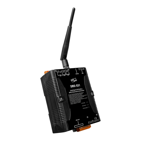
- Page 1 SMS-531 Intelligent 3G Modbus SMS/Voice Alarm Controller User’s Manual V1.1 High Quality, Industrial Data Acquisition, and Control Products...
- Page 2 SMS-531 User’s Manual v1.1 Warranty All products manufactured by ICP DAS are warranted against defective materials for a period of one year from the date of delivery to the original purchaser. Warning ICP DAS assumes no liability for damages consequent to the use of this product.
-
Page 3: Table Of Contents
3.2 Installing GT-531 Series Utility................. 11 4. The GT-531 Series Utility Operation Description ......14 4.1 Main Menu ....................... 15 4.2 File Menu ......................17 4.3 Connecting to the SMS-531 ................17 4.4 Parameters ......................18 4.4.1 System ....................18 4.4.2 COM Port ....................20 4.4.3 Phone Book ................... - Page 4 SMS-531 User’s Manual v1.1 5.5 Example 5: Receiving the SMS ................ 48 5.6 Example 6: Sending the general alarm SMS (Edge Trigger) ......53 6. SMS-531 Modbus Address Table ............57 7. Troubleshooting ..................60...
-
Page 5: Introduction
SMS-5xx series remotely, ICP DAS provides SMS DBS software for users to apply in the system. Therefore, the SMS-531 can be a powerful tool allowing you to use your mobile phone to monitor and control your business from any location. -
Page 6: Features
SMS-531 User’s Manual v1.1 1.1 Features Support GSM 850/900/1800/1900 MHz Quad-band frequency Support WCDMA 850/900/1900/2100 MHz Quad-band frequency Support Modbus RTU slave protocol Support max. 256 short messages and voice alarms Support max. 70 Unicode Characters ... - Page 7 SMS-531 User’s Manual v1.1 Application 1:Signal Alarm and SMS Communication Application 2:Home Security Application 3:Remote Maintenance - 3/60 -...
-
Page 8: Hardware
SMS-531 User’s Manual v1.1 2. Hardware 2.1 Specifications System 32 bit CPU SRAM 64K Bytes Flash Memory 512K Bytes WDT(watchdog) Serial Ports RS-232 : TXD,RXD,GND:Configuration and Debug COM1 RS-232 : TXD,RXD,GND:Communicating with the Host COM2 RS-485 : D+,D-:Communicating with the Host... -
Page 9: Appearance And Pin Assignments
SMS-531 User’s Manual v1.1 2.2 Appearance and Pin Assignments Pin assignments of SMS-531 Power Input COM Port Terminal No. Terminal No. Assignment Assignment COM3 RS-485 TxD2 COM2 RxD2 RS-232 Initial Init Power Input: DC.+VS 10 ~ 30 VDC DC.GND TxD1... -
Page 10: Dimensions
SMS-531 User’s Manual v1.1 2.3 Dimensions - 6/60 -... -
Page 11: Led Indicators
3G module fail Blanking*1 (2 sec) Off or Blanking (not 2 sec) Note: When the SMS-531 sends voice alarm, the 3G LED is continuous on. STA (Orange): The System LED is to indicate if the SMS-531 is normal or fail. Normal(idle) Running... -
Page 12: Installing The Sms-531
SMS-531 User’s Manual v1.1 2.5 Installing the SMS-531 If users want to start SMS-531 normally, it needs to follow these steps to install the SMS-531 below: A. Install the antenna Plug in the normal SIM card (Before apply the SIM card, confirm it is OK by mobile phone.) -
Page 13: Installing The Gt-531 Series Utility
SMS-531 User’s Manual v1.1 3. Installing the GT-531 Series Utility It needs the runtime environment with .NET Framework 2.0 or above to execute the GT-531 Series Utility in the PC. If there has .NET Framework 2.0 or above in the PC, the section 3.1 can be omitted. - Page 14 SMS-531 User’s Manual v1.1 (3) The installation process would be going. (4) After finishing the installation, press “Finish” to exit the program. - 10/60 -...
-
Page 15: Installing Gt-531 Series Utility
SMS-531 User’s Manual v1.1 3.2 Installing GT-531 Series Utility A. Plug in the shipment CD into the PC Execute \software\pc_utility\Install_GT531_Series_Utility_Vxxx.exe The installation figure is as follows: (1) Press “Next” to start the installation procedure. (2) Select the installation path. The default path is ”C:\Progrm Files\GT-531 Series Utility”. - Page 16 SMS-531 User’s Manual v1.1 (3) Input the name shown in “All Programs”. Press “Next” to the next step. (4) After finishing the installation procedure, press “OK” to the next step. - 12/60 -...
- Page 17 SMS-531 User’s Manual v1.1 (5) Press “Finish” to finish the installation procedure. (6) Launch GT-531 Series Utility from the start menu: “Start → All Programs → GT-531 Series Utility → GT-531 Series Utility”. - 13/60 -...
-
Page 18: The Gt-531 Series Utility Operation Description
4. The GT-531 Series Utility Operation Description Before GT-531 Series Utility is connected to the SMS-531, please confirm these following steps: The STA LED is blanking. There are 2 kinds of blanking in the SMS-531. STA LED Description Blanking per 1 sec Normal mode The PIN/PUK code is wrong. -
Page 19: Main Menu
These tools include all the function operation of the GT-531 Series Utility. The description is as follows. Project: The parameters of the SMS-531 can be saved as the project file. The operation functions include “New”, “Open”, “Save”, “Save as…”, and etc... Language: The GT-531 Series Utility only support English interface now. - Page 20 Providing the simple way for users to learn the Modbus RTU commands to operate SMS-531. System: Providing some system operations include ”Signal Quality”, ”Reboot SMS-531”, ”Recover Default Settings”, ”Firmware Version”, ”Input PIN/PUK” and ”Voice File Management”. Parameter groups There are four parameter groups in the GT-531 Series Utility including “System”, ”COM Port”, ”Phone Book”...
-
Page 21: File Menu
For connecting to the SMS-531, you can follow the steps below. A. Select the COM port of the host PC and connect to the COM1 of SMS-531. Press ”Connect” to connect to the SMS-531. If the connection is failed, check the COM port settings and wiring. -
Page 22: Parameters
4.4.1 System There are 6 items in the system field below. A. Protocol: The communication protocol of the SMS-531.The current protocol is Modbus RTU. It can not be changed. Module Address: To show or set the Modbus ID of the SMS-531. - Page 23 SMS-531 User’s Manual v1.1 D. SMS Check Number: Disabling or enabling the check code for SMS. If the SMS-531 is applied with the SMS DB system of ICP DAS, the check code function must be enabled and user must add “ALARM;” to the start of the short message.
-
Page 24: Com Port
SMS-531 User’s Manual v1.1 4.4.2 COM Port The parameters of COM Port (COM2, COM3) Parameters Description Port COM Port name (read only) Data Bit Only 8 bits Stop Bit 1 or 2 bits Parity Bit None, Even, Odd 2400、4800、9600、19200、38400、57600、115200 bps Baudrate 4.4.3 Phone Book... - Page 25 SMS-531 User’s Manual v1.1 Delete Group You can delete a group by right clicking the group from the left windows as the following figure. D. Adding, changing or deleting the phone numbers in the groups By clicking the group from the left windows, you can add, change or delete the phone number from the right windows.
-
Page 26: Alarm Message
The parameters in “Alarm Message” can define the SMS content and phone groups according with alarm channels. Parameters Description Alarm Channel The Alarm number of the SMS-531 On Message The transmitting SMS content when alarm is on Off Message The transmitting SMS content when alarm is off... -
Page 27: Downloading/Uploading The Sms-531'S Parameters
A. Downloading parameters As the configuration is finishing, the function can download the parameters to the SMS-531 by clicking “Download” as the following figure. Uploading parameters “Upload” button can upload the parameters from the SMS-531 as the following figure. - 23/60 -... -
Page 28: Learning Modbus Rtu Commands And Testing
4.6 Learning Modbus RTU Commands and Testing The “Learn” function provides a quick way to learn and test the Modbus commands for the SMS-531 as the following figure. There are 2 functions in the windows. The description is as follows: A. - Page 29 Receive SMS The function provides how to get the received SMS from the SMS-531. The SMS-531 can filter the SMS if the SMS is not transmitted from the phone of the groups. Getting the SMS steps are described as follows.
-
Page 30: System
Click “System->Signal Quality” can show the signal quality windows to know the 3G signal strength. A. Field Description: The strength is divided into 5 sections shown in percentage. Operation: Read:Read the 3G signal strength from the SMS-531. - 26/60 -... -
Page 31: Inquiring Firmware Version
GT-531 Series Utility and firmware. A. Field Description: (1) Firmware version: show the version information the of SMS-531’s firmware (2) Utility version: show the version information of the SMS-531’s utility Operation: Read: Read these information from the SMS-531. - 27/60 -... -
Page 32: Inputting The Pin/Puk Code
SMS-531 User’s Manual v1.1 4.7.3 Inputting the PIN/PUK Code When the SMS-531 starts and the STA LED is blanking per 50 ms, it is needed to input the PIN or PUK code in the SMS-531. In this condition, click “System->Input PIN/PUK”... -
Page 33: Voice File Management
Channel: Alarm number Value: Alarm status Existed: Showing the voice file whether is in the root path of the SMS-531 File at Device: The voice file name in the SMS-531 is fixed and unchangeable and is to the corresponding alarm number. -
Page 34: Reset The Sms-531
8 kHz,11 kHz 4.7.5 Reset the SMS-531 Clicking “System->Reboot SMS-531” button can reset the SMS-531 as follows. 4.7.6 Recover to the Factory Settings It can recover the SMS-531 to the default settings by clicking “System->Recover Default Settings”. - 30/60 -... -
Page 35: Language
SMS-531 User’s Manual v1.1 4.8 Language “Language” can define the interface language of the GT-531 Series Utility. It only support English interface now. 4.9 Exit This function would exit the GT-531 Series Utility. - 31/60 -... -
Page 36: Example
SMS-531 User’s Manual v1.1 5. Example We provide 6 examples for users to learn how to operate the SMS-531. Example Description Example 1: This example shows how to send the fixed Sending the general alarm SMS content alarm SMS by Modbus commands in (Level Trigger) Level Trigger mode. -
Page 37: Example 1: Sending The General Alarm Sms (Level Trigger)
This example shows the steps to send the defined SMS to the defined phones in Level Trigger mode. Setting the parameters by the GT-531 Series Utility (1) Connect to the SMS-531. The Alarm Mode field will be enabled. (2) Choose the level trigger mode. (3) New and name an “Example1.prj” project in the Utility. - Page 38 SMS-531 User’s Manual v1.1 (4) Set the modbus address as 1. (The factory default address is 1) (5) Add 2 new phone groups and input phone numbers as follows: (6) Set the Alarm Channel0 and Channel1 separately as follows: Note: Trigger time field can't be used in Level Trigger mode.
- Page 39 (7) Connect to the SMS-531 and download these parameters to it. Modbus RTU commands (1) Connect COM2 (RS-232) or COM3 (RS-485) of the SMS-531 to the Host. (2) Sending the Modbus commands from the Host to the SMS-531 to transmit the alarm SMS as follows: - 35/60 -...
- Page 40 Command 01 05 00 00 FF 00 8C 3A Commands (Hex) Response 01 05 00 00 FF 00 8C 3A 1. The SMS-531 receives the Modbus command then sends the alarm message. 2. The content of the alarm SMS is “On Message” of Alarm Channel0 Description message.
-
Page 41: Example 2: Sending The Variable Alarm Sms
SMS-531 User’s Manual v1.1 5.2 Example 2: Sending the variable alarm SMS This example explains the procedure of the sending variable alarm SMS to the defined phones. The alarm SMS includes the content defined in “Alarm Messages” (max 54 chars) and the content (max 16 chars) by Modbus command. - Page 42 (4) Set the Alarm Channel0 and Channel1 separately as follows: (5) Connect to the SMS-531 and download these parameters to the SMS-531. Modbus RTU Command (1) Connect COM2 (RS-232) or COM3 (RS-485) of the SMS-531 to the Host. - 38/60 -...
- Page 43 Result SMS is “Channel1 ON+VSMS”. Format Description: Setting the variable SMS content Byte 0 The Modbus Address of the SMS-531 Byte 1 Function Code = 16 Byte 2 ~ 3 The start address of the variable content of the SMS...
- Page 44 Byte 2 02: Format error Byte 3 ~ 4 CRC-16 check code Sending the SMS Byte 0 The Modbus Address of the SMS-531 Byte 1 Function Code = 0x05 Byte 2 ~ 3 Alarm Channel Command =0xFF00, Sending the field content of “On Message”...
-
Page 45: Example 3: Sending The Alarm Sms Dynamically
(1) Connect to COM2(RS-232) or COM3(RS-485) of the SMS-531 to the Host PC. (2) The host sends the Modbus commands to the SMS-531 to set the content of the SMS and phone number first. Then, send the command to transmit the SMS. - Page 46 The Modbus Address of the SMS-531 Byte 1 = 0x90 Error Code Error response Byte 2 02: The SMS-531 is sending the SMS. The phone number is unchangeable. Byte 3 ~ 4 CRC-16 check code Setting the content of the SMS Byte 0...
- Page 47 Byte 1 = 0x90 Error Error Code Response Byte 2 02: The SMS-531 is sending the SMS. The content of the SMS is unchangeable. Byte 3 ~ 4 CRC-16 check code Sending the SMS (Function Code 5) Byte 0 The Modbus Address of the SMS-531...
- Page 48 SMS-531 User’s Manual v1.1 Sending the SMS (Function Code 15) Byte 0 The Modbus Address of the SMS-531 Byte 1 Function Code = 0x0F Byte 2 ~ 3 = 0x0080 Command Byte 4 ~ 5 = 0x0001 Byte 6 = 0x01...
-
Page 49: Example 4: Sending The Alarm Voice
SMS-531 User’s Manual v1.1 5.4 Example 4: Sending the alarm voice This example is shown how to send the defined voice alarm via the SMS-531. Setting the parameters by the GT-531 Series Utility (1) New and name an “Example4.prj” project in the Utility. - Page 50 SMS-531 User’s Manual v1.1 (5) Connect to the SMS-531 and download these parameters to the SMS-531. (6) Select the “System->Voice File Management” to download or confirm the voice files of the Alarm0 ON/OFF and Alarm1 ON/OFF are in the SD card.
- Page 51 Command (16 Hex) Response 01 05 00 00 FF 00 8C 3A 1. As the SMS-531 receives the command, it would sent the voice alarm. If the “SMS Alarm” is set as enable, the SMS would be sent. Description 2. The voice file is DO0_ON.WAV.
-
Page 52: Example 5: Receiving The Sms
(2) Set the Modbus address as 1 (the factory default address is 1). (3) Add a new phone group and input phone numbers above. The SMS-531 is built-in the phone filter. The SMS would be received according to the defined phone numbers. - Page 53 SMS-531 User’s Manual v1.1 (2) The host can send the Modbus command periodically to inquire the SMS-531 whether has received the SMS. If the SMS-531 has received the SMS, you can send the command to read it. Command and Description:...
- Page 54 The phone of transmitting SMS:886928766507 Date:20110422095531(2011/04/22/ 09:55:31) Result The SMS:Hello,GT-531! Format Description: Inquiring the SMS-531 whether has received the SMS Byte 0 The Modbus Address of the SMS-531 Byte 1 Function Code = 2 The address to indicate whether the SMS-531 has...
- Page 55 SMS-531 User’s Manual v1.1 Byte 0 The Modbus Address of the SMS-531 Byte 1 = 0x84 Error Error Code Response Byte 2 02: Error format Byte 3 ~ 4 CRC-16 check code Reading the date of the SMS Byte 0...
- Page 56 SMS-531 User’s Manual v1.1 Byte 165 ~ 166 CRC-16 check code Byte 0 The Modbus Address of the SMS-531 Byte 1 = 0x84 Error Error Code: Response Byte 2 02: Error format Byte 3 ~ 4 CRC-16 check code Clear the SMS from the SMS-531...
-
Page 57: Example 6: Sending The General Alarm Sms (Edge Trigger)
This example shows the steps to send the defined SMS to the defined phones in Edge Trigger mode. Setting the parameters by the GT-531 Series Utility (1) Connect to the SMS-531. The Alarm Mode field will be enabled. (2) Choose the edge trigger mode. (3) New and name an “Example6.prj” project in the Utility. - Page 58 SMS-531 User’s Manual v1.1 (4) Set the modbus address as 1. (The factory default address is 1) (5) Add 2 new phone groups and input phone numbers as follows: (6) Set the Alarm Channel0 and Channel1 separately as follows: - 54/60 -...
- Page 59 (7) Connect to the SMS-531 and download these parameters to it. Modbus RTU commands (1) Connect COM2 (RS-232) or COM3 (RS-485) of the SMS-531 to the Host. (2) Sending the Modbus commands from the Host to the SMS-531 to transmit the alarm SMS as follows: Commands and Description:...
- Page 60 SMS-531 User’s Manual v1.1 Command Format: Send the alarm SMS Byte 0 The Modbus Address of the SMS-531 Byte 1 Function Code = 0x05 Byte 2 ~ 3 Alarm Channel Command =0xFF00, Sending the field content of “On Message”. Byte 4 ~ 5 =0x0000, Sending the field content of “Off Message”.
-
Page 61: Sms-531 Modbus Address Table
SMS-531 User’s Manual v1.1 6. SMS-531 Modbus Address Table The Modbus function codes supported in the SMS-531 are 1, 2, 3, 4, 5, 6, 15 and 16. The Modbus address distribution is as the following table. (1) Coil Status (Function Code: 1, 5, 15) - Page 62 SMS-531 User’s Manual v1.1 (3) Input Register (Function Code: 4) Data Address Description Attribute Address The status of transmitting SMS buffer 0~15 (1) High Byte:Buffer status 0-> Idle 30001 ~ 0x0 ~ 1-> Waiting for transmitting 30016 2-> Transmitting 3-> Transmitting OK 4->...
- Page 63 SMS-531 User’s Manual v1.1 (4) Holding Register(Output Register) (Function Code: 3, 6, 16) Data Address Description Attribute Address Module Address(Modbus Net ID),1~247 40200 0xC7 COM2 (1) High Byte Code 0x04 0x05 0x06 0x07 Baud 2400 4800 9600 19200 Code 0x08...
-
Page 64: Troubleshooting
3. Check the 3G signal strength. It shows the SIM card needs to input PIN or PUK code. The SMS-531 is not set these code STA led is blanking per 50 ms. or the wrong codes. You can set these code in ”System->Input PIN/PUK”.
Need help?
Do you have a question about the SMS-531 and is the answer not in the manual?
Questions and answers