Table of Contents
Advertisement
Available languages
Available languages
Quick Links
ARTICOLI & APPARECCHI PER MEDICINA
NUOVO MONITOR PAZIENTE CMS 8000
Manuale d'uso
35152 / CMS8000
CONTEC MEDICAL SYSTEMS CO., LTD
No.112 Qinhuang West Street,
Economic & Technical Development Zone,
Qinhuangdao, Hebei Province, PEOPLE'S REPUBLIC OF CHINA
Made in China
Shanghai International Holding Corp. GmbH (Europe)
Eiffestrasse 80, 20537 Hamburg, Germany
0123
Advertisement
Chapters
Table of Contents
Troubleshooting

Related Manuals for Gima CONTEC CMS 8000


Summary of Contents for Gima CONTEC CMS 8000
- Page 1 ARTICOLI & APPARECCHI PER MEDICINA NUOVO MONITOR PAZIENTE CMS 8000 Manuale d’uso 35152 / CMS8000 0123 CONTEC MEDICAL SYSTEMS CO., LTD No.112 Qinhuang West Street, Economic & Technical Development Zone, Qinhuangdao, Hebei Province, PEOPLE’S REPUBLIC OF CHINA Made in China Shanghai International Holding Corp.
- Page 2 Copyright Dichiarazione La nostra società detiene tutti i diritti sul presente lavoro, inedito, e intende mantenere il presente lavoro riservato. Possiamo anche proteggere il presente lavoro come copyright non pubblicato. La presente pubblicazione deve essere utilizzata esclusivamente come riferimento per il funzionamento, manutenzione e riparazione delle nostre apparecchiature.
- Page 3 Garanzia Lavorazione e materiali La nostra società garantisce i dispositivi nuovi non consistenti in accessori nuove apparecchiature diverse dagli accessori come privi di difetti di materiali e di lavorazione per un periodo di 18 mesi (sei mesi per le sonde multi-sito e il sensore SpO ) dalla data di spedizione nelle normali condizioni di utilizzo e assistenza.
- Page 4 Politica di reso Procedura di reso Quando sia necessario restituire un'unità alla nostra società, è necessario seguire la seguente procedura: Ottenere l'autorizzazione al reso. Contattare il nostro servizio di assistenza e comunicare il numero di serie del prodotto. Il numero è indicato sulla parte esterna dell’imballo di spedizione. I resi non saranno accettati se detto numero non sarà...
-
Page 5: Table Of Contents
Indice Capitolo 1 Sicurezza ..............................1 1.1. Informazioni sulla sicurezza ........................1 1.2 Misure precauzionali ............................2 Capitolo 2 Generalità ..............................4 2.1 Introduzione ..............................4 2.2 Controindicazioni ............................4 Unità principale ...........................4 2.4 Display................................10 Capitolo 3 Installazione ............................12 Apertura dell’imballo e verifica del contenuto ..................12 3.2 Requisiti ambientali ............................13 3.3 Installare il monitor ............................13 3.4 Collegare i cavi di alimentazione .......................13... - Page 6 Capitolo 7 Registrazione ............................35 7.1 Informazioni generali sul registratore ......................35 7.2 Tipo di registrazione e stampa .........................35 7.3 Avvio e arresto di registrazione e stampa ....................37 7.4 Funzioni e messaggi di stato del registratore ....................38 Capitolo 8 Richiamo ..............................40 8.1 Grafico del trend ............................40 8.2 Tabella del trend ............................42 8.3 Richiamo della NIBP ..........................43 8.4 Richiamo degli allarmi ..........................43...
- Page 7 13.1 Introduzione ..............................80 13.2. Informazioni sulla sicurezza ........................80 13.3 Limiti della misurazione ........................81 13.4 Procedura di misurazione .........................81 13.5 Suggerimenti per l’uso..........................82 13.6 Rettifica dei risultati ..........................83 13.7 Visualizzazione della NIBP ........................83 13.8 IMPOSTAZIONI NIBP .........................83 13.9 Taratura NIBP ............................87 13.10 Messaggio di allarme NIBP ........................87 Capitolo 14 Monitoraggio TEMP ..........................90 14.1 Introduzione ............................90...
- Page 8 17.4 Verificare le prestazioni della batteria ....................108 17.5 Manutenzione della batteria........................109 17.6 Smaltimento della batteria ........................110 Capitolo 18 Manutenzione e pulizia ........................111 18.1 Introduzione ............................111 18.2 Pulizia ..............................111 18.3 Disinfezione ............................113 Capitolo 19 Manutenzione ............................. 114 19.1 Controllo ..............................
-
Page 9: Capitolo 1 Sicurezza
Capitolo 1 Sicurezza 1.1. Informazioni sulla sicurezza AVVERTENZA Prima di utilizzare il dispositivo, è necessario controllare l'apparecchiatura, il cavo paziente, gli elettrodi ecc. Sostituire le parti che presentano difetti evidenti o segni di obsolescenza, perché possono compromettere la sicurezza di pazienti e utenti e le prestazioni del dispositivo. Il monitor è... -
Page 10: Misure Precauzionali
ATTENZIONE! La durata del monitor è di 5 anni. Al termine della sua vita utile, il prodotto descritto in questo manuale e i suoi accessori, devono essere smaltiti in conformità con le relative normative locali e ospedaliere. In caso di domande relative allo smaltimento del prodotto, contattare la nostra società... - Page 11 Il contenuto più basilare della formazione sulla procedura precauzionale ESD prevede un'introduzione alla fisica delle cariche elettrostatiche, sui livelli di tensione convenzionali e sui danni ai componenti elettronici in caso di contatto con operatore portatore di carica elettrostatica. Inoltre, la formazione deve comprendere i metodi per prevenire l'accumulo elettrostatico, le modalità...
-
Page 12: Capitolo 2 Generalità
Capitolo 2 Generalità 2.1 Introduzione Struttura e composizione: unità principale, accessori (cavi di derivazione ECG, sensore SpO , tubo di prolunga NIBP, bracciale NIBP, sonda TEMP, ecc.) e cavo di alimentazione. Il monitor serve al monitoraggio clinico di pazienti adulti, pediatrici e neonati (in America la funzione SpO non è... - Page 13 CMS8000 CMS9000...
- Page 14 Indicatore di alimentazione a corrente alternata (AC) ON: il monitor è collegato all'alimentazione AC OFF: il monitor non è collegato all'alimentazione AC. Indicatore di stato della batteria: è verde lampeggiante durante la carica della batteria, è arancione durante la ricarica e verde a carica completata. O Indicatore di marcia: quando si accende il dispositivo, si accende questo indicatore;...
- Page 15 Vista laterale CMS7000 CMS8000 CMS9000...
- Page 16 T1: Presa per sonda TEMP canale 1 Presa per sensore SpO ECG: Presa per cavo ECG NIBP: Presa per bracciale NIBP T2: Presa per sonda TEMP canale 2 Nota: [6] e [7] non possono essere collegati a una IBP/CO : Interfaccia IBP o CO funzione contemporaneamente;...
- Page 17 CMS9000 Interfaccia di rete: interfaccia RJ45 standard, collega al sistema di monitoraggio centrale della nostra azienda società mediante cavo di rete Porta USB: collegamento con dispositivi di memoria esterni Terminale di messa a terra equipotenziale: quando si usa il monitor insieme ad altri dispositivi, collegare con un cavo gli altri dispositivi al terminale equipotenziale del monitor, per eliminare la differenza di potenziale di terra tra i diversi dispositivi e garantire la sicurezza.
-
Page 18: Display
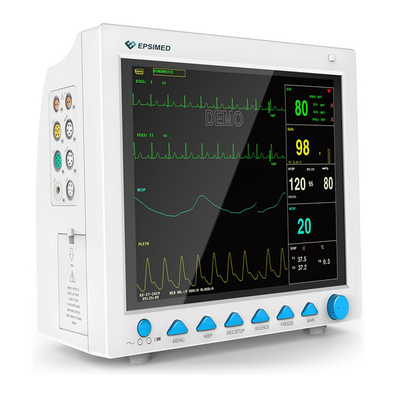
2.4 Display Il monitor è dotato di schermo TFT LCD a colori ad alta risoluzione, per la chiara visualizzazione di tutti i parametri e le forme d'onda del paziente. La figura seguente mostra l'interfaccia standard nel normale stato di monitoraggio. 1.indicatore della batteria La batteria funziona normalmente, la parte colorata indica il livello della batteria. - Page 19 6.Data e ora Indica la data e l'ora correnti, impostabili secondo necessità. 7.Area della forma d'onda Visualizza principalmente la forma d'onda dei parametri fisiologici, il nome della singola forma d’onda si trova in alto a sinistra. Si può selezionare la derivazione ECG. La modalità filtro viene visualizzata nella parte superiore dello schermo. Il guadagno di ogni canale è...
-
Page 20: Capitolo 3 Installazione
Capitolo 3 Installazione Il monitor portatile è stato progettato per soddisfare i requisiti di sicurezza di IEC 60601-1, IEC 60601-2-27 e IEC 80601-2-30 per i dispositivi elettromedicali. Il sistema ha un ingresso flottante per protezione da defibrillatore e da bisturi elettrochirurgico. Se si usano e si posizionano correttamente gli elettrodi (cfr. la sezione sul monitoraggio ECG) secondo le istruzioni del produttore, il display si ripristina entro 5 secondi dalla defibrillazione. -
Page 21: Requisiti Ambientali
bambini. Il dispositivo può subire contaminazione biologica durante lo stoccaggio, il trasporto e l’utilizzo. Verificare che la confezione sia integra prima dell'uso, in particolare gli accessori monouso. Se si rilevano danni, non utilizzare. NOTA: Conservare l'imballo e i materiali di imballaggio per eventuale trasporto e stoccaggio futuri. 3.2 Requisiti ambientali Attenersi alle seguenti istruzioni per garantire la sicurezza dell'installazione elettrica. -
Page 22: Accensione
normalmente a causa della mancanza di elettricità. Il dispositivo può essere caricato sia da acceso sia da spento collegandolo all'alimentazione in corrente alternata. Messa a terra Per proteggere i pazienti e il personale medico, la custodia del monitor portatile deve essere debitamente messa a terra. A tal fine il monitor portatile è... -
Page 23: Spegnimento
2. Ispezione funzionale Avvio Collegare il cavo di alimentazione alla porta di alimentazione in corrente alternata. Se il dispositivo utilizza la batteria interna per l'alimentazione, Verificare che la batteria sia sufficientemente carica. Accendere il monitor paziente, che dovrebbe avviarsi normalmente: •... -
Page 24: Capitolo 4 Menu Di Sistema
Capitolo 4 Menu di sistema Il presente monitor presenta offre flessibilità di configurazione. È possibile personalizzare il contenuto di monitoraggio, la velocità di scansione delle forme d’onda, il volume dei suoni e i contenuti in uscita. Premere il tasto MENU sul pannello frontale del monitor, apparirà... -
Page 25: Impostazioni Di Default
DELETE: per cancellare le informazioni del paziente precedente e inserire un nuovo paziente Cliccando sul tasto "DELETE” (”cancella”) di questo menù, si apre la finestra di dialogo "CONFIRM TO DELETE” (“conferma cancellazione”): "YES” (“sì”) per cancellare le informazioni del paziente, "NO" per non cancellarle. NOTA: Se si sceglie "YES", le informazioni del paziente corrente vengono cancellate. -
Page 26: Impostazione Del Sistema
4.4 Impostazione del sistema Selezionando la voce "SYSTEM SETUP" nel "SYSTEM MENU", si apre il seguente menù: Nel menù "SYSTEM SETUP", l'utente può impostare le seguenti voci. 4.4.1 Selezione della schermata di interfaccia Il sistema offre 5 interfacce: "STAND SCREEN", "OxyCRG SCREEN", "TREND SCREEN", "BIG CHAR" e "VIEWBED SCREEN". - Page 27 1. SCHERMATA STAND "STAND SCREEN" è l'impostazione predefinita. Se l’interfaccia corrente non è la schermata standard, è possibile accedere a quest’ultima selezionando "STANDARD SCREEN" e poi "EXIT" dal menù FACE SELECT. Stand Screen 2. SCHERMATA OxyCRG Per accedere a questa interfaccia, selezionare "OxyCRG SCREEN” e poi selezionare "EXIT" nel menù "FACE SELECT".
- Page 28 ①. Lunghezza della forma d'onda Questa etichetta consente di selezionare la durata temporale dei grafici dei trend visualizzati. Si possono selezionare 1 minuto, 2 minuti o 4 minuti. ② Trend della forma d'onda compressa RESP/RR Con questa etichetta si visualizzano la forma d'onda compressa della respirazione o il trend RR. Si possono selezionare RESP WAVE o RR.
- Page 29 4. BIG CHAR Per visualizzare i parametri in modo più chiaro anche a una certa distanza. Big Char 5. SCHERMATA VIEWBED Il monitor può visualizzare la forma d'onda di un parametro e tutti i dati misurati da un altro monitor paziente facente parte della stessa rete di monitoraggio.
- Page 30 ① Etichetta del viewbed monitor L'etichetta “viewbed monitor” consente di selezionare l’altro monitor paziente di cui si desidera visualizzare i dati. Visualizza il numero del letto e il nome del paziente monitorato dal viewbed monitor. ② Area dei parametri viewbed Tutti i dati dei parametri del viewbed monitor vengono visualizzati in questa area.
- Page 31 selezionare l'ora desiderata. Infine, selezionare "SAVE SET". NOTA: L'ora del sistema va impostata all'accensione del monitor (se necessario); diversamente, quando si procede alla rivisualizzazione dei contenuti, il sistema potrebbe indicare un orario non corretto. 4.4.7 Impostazioni d’allarme Fate riferimento al monitor in vostre mani. 4.4.8 Impostazioni di registrazione Selezionare "RECORD"...
-
Page 32: Versione Della Macchina
"EXIT" per uscire dal menù e convalidare le selezione effettuata. 4.4.10 SD OPERATE Vedere il capitolo Richiamo SD . 4.5 Versione della macchina Selezionare "VERSION" in "SYSTEM MENU". Il menù a comparsa indica la versione del software del monitor. Nome del software CMS8000 CMS9000 (CMS7000) Specifiche... - Page 33 4.7.2 Manutenzione a cura del produttore 1. Selezionare "MAINTAIN" in "SYSTEM MENU", quindi selezionare "FACTORY KEY". 2. Immettere la password per accedere al menù della manutenzione a cura del produttore. Questa funzione è disponibile solo ai tecnici della manutenzione della nostra società. 4.7.3 Configurazione di rete Cliccare su "NIT CONFIGUR", appare il seguente menù: NET TYPE: CMS/CUSTOM...
- Page 34 L'IP del server è fisso: "202.114.4.119". Una volta che il monitor ha specificato il numero di porta, il programma ottiene automaticamente l'indirizzo IP locale e la porta di connessione. CUSTOM In questa modalità l’utente può impostare l'indirizzo IP e la subnet mask del server e di questo monitor... LAN CARD SET: 3G/WIRELESS/VIA CAVO La rete 3G viene utilizzata principalmente per connettersi con il sistema di monitoraggio centrale tramite Internet WAN.
-
Page 35: Demo
(IP dinamico di questo monitor, gateway, DNS, ecc.) tramite DHCP. Se si usa un IP specifico, inserire l'indirizzo IP del monitor e la subnet mask e cliccare su "LOCAL IP CONFIG"; appare allora il seguente menù: Via cavo Quando il tipo di rete è CMS, accertarsi che la connessione tra il dispositivo e la stazione centrale sia corretta. (L'indirizzo IP del server è... -
Page 36: Capitolo 5 Allarmi
Capitolo 5 Allarmi Quando il paziente monitorato mostra alterazioni anomale dei segni vitali o si verifica un guasto nel monitor che impedisce il corretto monitoraggio del paziente, il dispositivo emetterà un allarme sonoro, luminoso o altro per avvertire l’operatore. AVVERTENZA In ogni unità... -
Page 37: Modalità Di Allarme
NOTA: Il livello di tutti gli allarmi tecnici e dei messaggi di prompt e alcuni degli allarmi fisiologici sono determinati dal sistema e l'utente non può modificarli. Il livello della maggior parte degli allarmi fisiologici va impostato dall'utente, come le soglie di allarme. 5.3 Modalità... -
Page 38: Impostazione Degli Allarmi
5.4 Impostazione degli allarmi Selezionare "ALARM SETUP" nel menù "SYSTEM SETUP", la password iniziale è "70808". Qui l'utente può impostare il suono e le altre caratteristiche degli allarmi. ALARM VOL: impostabile da 1 a 7, 1 è il volume minimo, 7 il volume massimo. ALM REC TIME: tre opzioni: 8 s, 16 s, 32 s. -
Page 39: Stato Degli Allarmi
Esistono due modi per uscire da questo stato. Metodo 1: Impostare il suono dell’allarme su "ON" in "ALARM SETUP". Metodo 2: Premere il tasto "SILENCE", il simbolo cambia in " ", quindi premere ancora una volta "SILENCE” per ripristinare la condizione normale degli allarmi. Impostazione degli allarmi per i diversi parametri 1. -
Page 40: Azioni In Caso Di Allarme
Silence Alarm sound off 5.5.1 Silence (silenzio) Esercitare una pressione lunga (più di 1 secondo) sul tasto "SILENCE" sul pannello di controllo per disattivare tutti i suoni. In stato SILENCE, premere per non più di 1 secondo il tasto "SILENCE" per passare allo stato "ALARM PAUSE": l'allarme andrà... -
Page 41: Allarme Probe Off (Sonda Scollegata)
5.7 Allarme probe off (sonda scollegata) All’attivarsi dell’allarme per sonda scollegata, premere il tasto "SILENCE" sul pannello frontale del monitor. La spia dell’allarme si spegne e il monitor entra nello stato ALARM PAUSE. Premere di nuovo il tasto "SILENCE" o attendere fino al termine della pausa dell'allarme;... -
Page 42: Rivisualizzazione Delle Forme D'onda Congelate
REC: il sistema inizia a registrare le forme d'onda congelate selezionate in "WAVE 1" e "WAVE 2". EXIT: premendo EXIT, il sistema chiude il menù FREEZE ed esce dallo stato freeze. 6.3 Rivisualizzazione delle forme d’onda congelate Spostando la forma d'onda se ne possono rivisualizzare i 34 secondi precedenti il congelamento. La parte oltre i 34 secondi di una forma d'onda di durata inferiore viene visualizzata come una linea retta. -
Page 43: Capitolo 7 Registrazione
Capitolo 7 Registrazione NOTA: Il registratore è un componente opzionale. Informazioni generali sul registratore Il monitor utilizza un registratore dotato di stampante termica. Prestazioni del registratore n Velocità di registrazione e stampa: 25 mm/s o 50 mm/s. n Larghezza di stampa della forma d’onda: 48 mm n Si possono registrare al massimo 2 forme d'onda per volta. - Page 44 NOTA: Se durante una registrazione un altro parametro genera un allarme che richiede registrazione, quest’ultima registrazione avverrà solo al termine della registrazione già in corso. Registrazione automatica Il monitor avvia una registrazione per 8 secondi previa impostazione dell'intervallo temporale in "TIMING REC TIME" del menù...
-
Page 45: Avvio E Arresto Di Registrazione E Stampa
Tabella di titolazione Il monitor può stampare i messaggi della corrente interfaccia TITRATION. Note su registrazione e stampa Tipo di registrazione e stampa: Registrazione e stampa in tempo reale Registrazione e stampa periodica Registrazione e stampa di allarme parametri Registrazione e stampa di aritmia Registrazione e stampa della forma d’onda congelata Grafico del trend Tabella del trend... -
Page 46: Funzioni E Messaggi Di Stato Del Registratore
Registrazione e stampa del grafico Selezionare il tasto "REC" nel menù "TREND GRAPH" per stampare il di tendenza grafico del trend attualmente visualizzato. Registrazione e stampa della tabella Selezionare il tasto "REC" nel menù "TREND TABLE" per stampare la di tendenza tabella dei trend attualmente visualizzata. - Page 47 Inserimento della carta Interrut tore Carta Sportello della stampante Premere l'interruttore per aprire lo sportello della stampante. Inserire un nuovo rotolo di carta nell’apposito vano, posizionando la carta e i in particolare i suoi bordi in modo corretto. Far uscire un poco di carta dalla fessura di uscita. Chiudi lo sportello della stampante.
-
Page 48: Capitolo 8 Richiamo
Capitolo 8 Richiamo Il monitor fornisce i dati del trend per 480 ore, per tutti i parametri, memorizza 4800 gruppi di risultati di misurazione NIBP e 72 eventi di allarme. Tutti questi dati possono essere stampati. Utilizzando la scheda SD si possono rivisualizzare i dati del trend e le forme d’onda ECG di 72 ore. - Page 49 Per modificare la scala di visualizzazione Selezionare "ZOOM" per regolare la scala dell'asse y e modificare di conseguenza la curva del trend. Il valore eccedente il valore massimo sarà indicato come valore massimo. Per ottenere i dati del trend di un momento specifico Selezionare "CURSOR"...
-
Page 50: Tabella Del Trend
8.2 Tabella del trend I dati delle ultime 480 tabelle del trend sono visualizzabili con risoluzione di 1 minuto, 5 minuti, 10 minuti, 30 minuti o 60 minuti. Selezionare TREND TABLE in SYSTEM MENU per aprire il menù seguente: Nell'elenco all'estrema sinistra viene visualizzato il tempo corrispondente a ciascun gruppo di dati del trend, con la data tra parentesi. -
Page 51: Richiamo Della Nibp
Esempio operativo Per visualizzare la tabella del trend della NIBP: Selezionare "MENU" sul pannello frontale per aprire il "SYSTEM MENU". Selezionare la voce TREND TABLE. Selezionare la voce "L-RIGHT” e poi selezionare "NIBP" ruotando la manopola. Regolare il valore "RESOLUTION” come desiderato. Selezionare il tasto "UP/DOWN”... -
Page 52: Richiamo Da Sd
L'interfaccia di PHYSIOLOGICAL ALARM RECALL è come segue: ① ② ③ ④ ⑤ ① Intervallo temporale (formato: anno/mese/giorno/ora/minuto --- anno/mese/giorno/ora/minuto). ② Tipo di evento. ③ Numero seriale (formato: n. xx di XX). ④ Valore al momento dell'allarmante. Non si riporta il risultato della misurazione della NIBP. ⑤... - Page 53 NOTA: Su PC, la rivisualizzazione con software di sincronizzazione consente di rivisualizzare solo le forme d'onda e i valori dei parametri di ECG e SpO . Si vedano in proposito le istruzioni del software di sincronizzazione. Il presente capitolo tratta esclusivamente della revisione sul monitor paziente. Si faccia attenzione a impostare correttamente le informazioni del paziente prima di inserire la scheda SD.
- Page 54 Questo menù comprende, da sinistra a destra, le voci: No., Patient No. Patient Name, Admission Date, Birth Date (n., n. paziente, nome paziente, data di ricovero, data di nascita). Le informazioni vengono visualizzate secondo le impostazioni selezionate per il paziente. La parte inferiore del menù contiene i tasti seguenti: PAGE UP/PAGE DOWN: per scorrere le pagine dell’elenco dei pazienti.
- Page 55 ③ Rivisualizzazione dei dati dei trend Con il cursore, selezionare una voce nel menù in alto usando, quindi premere il tasto "REVIEW": appare un elenco con i dati dei trend . La risoluzione è di 1 minuto. I tasti sono: PAGE UP/PAGE DOWN: per scorrere tra i dati dei trend registrati nei diversi momenti.
- Page 56 Rivisualizzazione della forma d'onda dell'ECG ① Selezionare "REVIEW ECG WAVE" nel menù SD OPERATE, quindi selezionare il paziente specifico. ② Selezionare l'intervallo di tempo da rivisualizzare I dati dell’ECG devono essere salvati in più file. Il salvataggio dei dati dell’ECG richiede la creazione di un nuovo file ogni mezz'ora.
- Page 57 ③ Rivisualizzare la forma d'onda dell'ECG L'intervallo di tempo della singola finestra è di 5 secondi. La finestra può visualizzare forme d'onda ECG a 3 canali. Per ECG di tipo “5-LEADS”, cioè a 5 derivazioni, vengono visualizzate le derivazioni ECG I, ECG II ed ECG V. 5 derivazioni Per ECG di tipo "3-LEADS”...
-
Page 58: Capitolo 9 Calcolo Dei Farmaci E Tabella Di Titolazione
Capitolo 9 Calcolo dei farmaci e tabella di titolazione Questo monitor paziente portatile consente il calcolo delle dosi dei farmaci e la visualizzazione delle tabelle di titolazione per quindici farmaci, e ne consente la stampa. 9.1 Calcolo dei farmaci Il sistema può calcolare le dosi dei seguenti farmaci: AMINOFILLINA, DOBUTAMINA, DOPAMINA, EPINEFRINA, EPARINA, ISUPREL, LIDOCAINA, NIPRIDE, NITROGLICERINA e PITOCINA. -
Page 59: Tabella Di Titolazione
il calcolo. Bisogna infatti inserire un nuovo gruppo di valori indicati dal medico come adeguati al paziente. Ogni farmaco ha la propria unità o serie di unità fisse. L'operatore deve selezionare l'unità corretta secondo le istruzioni del medico. L'unità si regola automaticamente secondo la serie di unità previste e il valore immesso. - Page 60 L'interfaccia della tabella di titolazione è come segue: Come utilizzare la tabella di titolazione: Nella tabella TITRATION, ruotare la manopola per selezionare la voce BASIC. Premere e ruotare la manopola per selezionare INF RATE o DOSE o DRIP RATE. Portare il cursore su STEP. Premere la manopola per selezionare il passo. L'intervallo selezionabile è 1 ~ 10. Portare il cursore su DOSE TYPE.
-
Page 61: Capitolo 10 Monitoraggio Ecg
Capitolo 10 Monitoraggio ECG 10.1 Introduzione Il monitoraggio ECG produce una forma d'onda continua dell'attività elettrica cardiaca del paziente per consentire una valutazione accurata dell'attuale stato fisiologico del paziente. Solo una corretta connessione delle cavi ECG garantisce una misurazione soddisfacente. Di norma, il monitor visualizza contemporaneamente le forme d'onda ECG a 2 canali e consente il monitoraggio a 3/5 derivazioni, l’analisi del segmento ST e l’analisi delle aritmie. -
Page 62: Procedura Di Monitoraggio
“Comunicazione modulo ECG interrotta", "Errore di comunicazione modulo ECG" o "Errore inizializzazione modulo ECG", il monitor interrompe automaticamente il monitoraggio e verrà emesso un allarme di livello alto. Gli elettrodi usati devono essere riciclati o smaltiti correttamente a tutela dell’ambiente. 10.3 Procedura di monitoraggio 10.3.1 Preparazione... - Page 63 Marrone/ rosso Bianco/ rosso Marrone/ giallo Bianco/ giallo Marrone/ verde Bianco/ verde Marrone/ blu Bianco/marrone Marrone/arancione Bianco/ nero Marrone/viola Bianco/viola ECG a 3 derivazioni Nell’ECG a 3 derivazioni, gli elettrodi vanno applicati come segue: RA (braccio destro): sotto la clavicola, vicino alla spalla destra LA (braccio sinistro): sotto la clavicola, vicino alla spalla sinistra LL (gamba sinistra): quadrante inferiore sinistro ECG a 5 derivazioni...
- Page 64 Per garantire la sicurezza del paziente, tutte le derivazioni devono essere collegate al paziente. Se il set è a 5 derivazioni, applicare l'elettrodo toracico (V) in una delle posizioni seguenti: V1: Sul 4° spazio intercostale sul margine destro dello sterno °...
- Page 65 Posizioni delle derivazioni ECG raccomandate per i pazienti chirurgici Il posizionamento delle derivazioni ECG dipende dal tipo di intervento chirurgico da eseguire. Per esempio, in caso di intervento a cuore aperto gli elettrodi possono essere posizionati lateralmente sul torace o sulla schiena. In sala operatoria, le attrezzature elettrochirurgiche (ES) possono provocare artefatti che si riflettono sulla forma d'onda dell'ECG.
-
Page 66: Tasti Di Scelta Rapida Della Schermata Ecg
Forma d’onda ECG standard 10.4 Tasti di scelta rapida della schermata ECG La figura seguente mostra un'interfaccia di monitoraggio a 5 derivazioni ed è proposta a mero scopo esemplificativo. ③ ① ② ④ ⑤ Tasto di scelta rapida ECG ① Derivazioni del canale 1: Le derivazioni disponibili sono I, II, III, aVR, aVL, aVF, V. -
Page 67: Impostazioni Ecg
③ Metodo di filtro: per visualizzare la forma d'onda in modo più chiaro e dettagliato Sono disponibili tre modalità di filtro. In modalità DIAGNOSTIC la forma d'onda ECG viene visualizzata senza filtro. In modalità MONITOR, vengono filtrati gli artefatti che potrebbero causare falsi allarmi . La modalità... - Page 68 di scelta rapida SpO L'allarme HR e l'allarme PR sono entrambi disponibili. In modalità BOTH, tra il segnale acustico di HR e di PR viene data priorità al primo, cioè se è disponibile il valore HR, il sistema emette il relativo segnale acustico, mentre se detto valore non è...
-
Page 69: Allarme Ecg E Messaggi Di Prompt
AVVERTENZA Per un paziente portatore di pacemaker, il cardiofrequenzimetro può rilevare e contare gli impulsi del pacemaker anche quando il paziente va in arresto cardiaco o presenta aritmia. Si raccomanda pertanto di non affidarsi esclusivamente sugli allarmi del cardiofrequenzimetro. I pazienti portatori di pacemaker devono essere monitorati con estrema attenzione. -
Page 70: Monitoraggio Del Segmento St
Le tabelle seguenti descrivono gli allarmi che possono attivarsi durante la misurazione. Allarmi fisiologici: Messaggio Causa Livello di allarme ECG SIGNAL WEAK Non viene rilevato alcun segnale ECG per il paziente. HIGH HR HI Il valore della frequenza cardiaca supera la soglia superiore di Selezionabile allarme. - Page 71 NOTA: Quando si attiva ST ANALYSIS, il monitor seleziona la modalità "DIAGNOSTIC". È possibile impostarlo sulla modalità "MONITOR" o sulla modalità "SURGERY", secondo necessità. In questo momento, tuttavia, il valore ST è gravemente distorto. 10.7.1 ST ON/OFF Per attivare o disattivare la visualizzazione del parametro ST: 1.
- Page 72 ISO e ST sono i due punti di misurazione nel segmento ST e sono entrambi regolabili. Il punto di riferimento è la posizione del picco dell'onda R (come nella figura seguente). Il valore ST per ciascuna onda complessa del battito cardiaco è la differenza tra i due punti di misurazione. Onda R Valore ST: -78 ms...
-
Page 73: Monitoraggio Arr
complesso QRS (se il canale non è attivo, appare io messaggio “ST ANALYSIS KEY IS OFF!” - Il tasto dell’analisi ST è su OFF!.). La regolazione avviene secondo le linee evidenziate nella finestra. Selezionare ISO o ST, quindi ruotare la manopola per spostare la linea di regolazione e decidere il punto di base e il punto di misurazione. NOTA: Le soglie di allarme per le due misurazioni ST sono uguali. - Page 74 10.8.1 Analisi ARR ON/OFF Per attivare o disattivare l'analisi ARR: 1. Selezionare "ECG ALM SETUP" nel menù "ECG SETUP", per i dettagli vedere "ECG SETUP"; 2. quindi selezionare "ARR ALARM" per accedere all’interfaccia e attivare o disattivare la funzione "ARR ANAL"...
- Page 75 Impostazione dell’allarme per aritmia Selezionare ALL ALM ON per abilitare la funzione di allarme per tutti i tipi di aritmia e selezionare ALL ALM OFF per disabilitarla. Analogamente, selezionare ALL REC ON per abilitare la funzione di registrazione per tutti i tipi di aritmia e selezionare ALL REC OFF per disabilitare questa funzione.
- Page 76 Nell'interfaccia di richiamo della forma d’onda dell'aritmia: ² UP/DOWN: Per visualizzare le forme d'onda di altri eventi di aritmia. ² CURSOR: Per visualizzare tutta la forma d'onda di 8s dell'evento di aritmia. ² RECORD: Per stampare la forma d'onda dell'evento di aritmia visualizzato. ²...
- Page 77 Onda di fibrillazione per 4 secondi consecutivi oppure portatore numero di battiti ventricolari in sequenza maggiore della Selezionabile VFIB /VTAC di pacemaker soglia superiore prevista (≥5). L'intervallo RR è inferiore dall'utente a 600 ms. portatore Selezionabile VT>2 3 < numero di PVC in sequenza <5 di pacemaker dall'utente portatore...
- Page 78 Messaggio di prompt: Livello Messaggio Causa d’allarme Nessun ARR LEARNING È in corso la creazione del modello QRS per l'analisi ARR. allarme NOTA: Nell’area degli allarmi viene visualizzato il nome dell'aritmia.
-
Page 79: Capitolo 11 Monitoraggio Resp
Capitolo 11 Monitoraggio RESP 11.1 Introduzione Metodo di misurazione: impedenza toracica. Durante la respirazione, l'attività toracica provoca un cambiamento nell'impedenza toracica tra i due elettrodi ECG. Il monitor produce e visualizza l’onda respiratoria misurando la variazione dell’impedenza (dovuta al movimento del torace), quindi calcola la frequenza respiratoria in base al ciclo della forma d’onda. -
Page 80: Impostazioni Resp
sovrapposizione dei segnali cardiaci e artefatti dovuti alle pulsazioni arteriose. Questo è particolarmente importante in caso di pazienti neonati. 11.4 Impostazioni RESP Premere il tasto di scelta rapida RESP sullo schermo per accedere all'interfaccia "RESP SETUP": ALM REC: selezionare "ON" per abilitare la stampa del report in caso di allarme RESP. SWEEP: 6,25 mm/s, 12,5 mm/s, 25,0 mm/s WAVE AMP: La forma d’onda RESP può... - Page 81 Allarmi tecnici Livello Messaggio Causa Rimedio d’allarme Verificare che tutti gli elettrodi, le derivazioni e i RESP LEAD OFF RA, RL or LL staccati. cavi siano collegati correttamente.
-
Page 82: Capitolo 12 Monitoraggio Spo
Capitolo 12 Monitoraggio SpO 12.1 Introduzione La misurazione del pletismogramma SpO serve a determinare la saturazione di ossigeno dell'emoglobina arteriosa. Per esempio, se il 97% delle molecole di emoglobina nei globuli rossi del sangue arterioso si combina con l'ossigeno, il sangue ha una saturazione di ossigeno SpO del 97%. -
Page 83: Misurazione Della Spo
diversi pazienti possono richiedere intervalli di verifica diversi. Il dispositivo non è adatto a soggetti allergici al silicone o all'ABS. La sonda SpO in dotazione è destinata esclusivamente all'uso con il presente questo monitor. Il monitor può utilizzare solo la sonda SpO in dotazione con esso e descritta nel presente manuale. -
Page 84: Limiti Della Misurazione
AVVERTENZA Controllare il sito di applicazione ogni 2-3 ore per garantire una buona consistenza della cute e un corretto allineamento della luce. In caso di danni alla cute, cambiare il punto di applicazione del sensore. È opportuno cambiare il sito di applicazione ogni 4 ore. NOTA: Non utilizzare ossimetri fotoelettrici e sensori SpO durante la risonanza magnetica (MRI), perché... -
Page 85: Impostazioni Spo
Il sensore SpO e il ricevitore fotoelettrico devono essere posizionati in modo che tra essi vi siano le arteriole del paziente. L’unghia del paziente deve essere libere da smalto e altri cosmetici. L’unghia del paziente non deve essere troppo lunga. 12.6 Impostazioni SpO Ruotare la manopola per spostare il cursore sul tasto di scelta rapida SpO nell'area parametri e premere la manopola su... -
Page 86: Messaggio Di Allarme Spo
chiede di confermare la selezione effettuata. 12.7 Messaggio di allarme SpO NOTA: L’allarme SpO .è immediato e non ritardabile. Informazioni sull'allarme SpO Quando nei relativi menù gli allarmi sono impostati su "ON", gli allarmi fisiologici innescati dal superamento dei valori soglia attivano il registratore, che stamperà... - Page 87 Messaggio di prompt: Messaggio Causa Livello d’allarme SEARCHING PR Il modulo SpO sta cercando il polso. Nessun allarme SEARCH TIMEOUT Il modulo SpO non rileva il segnale SpO per un HIGH periodo protratto.
-
Page 88: Capitolo 13 Monitoraggio Nibp
Capitolo 13 Monitoraggio NIBP 13.1 Introduzione Metodo di misurazione: Metodo oscillometrico Si applica ai pazienti adulti, pediatrici e neonati. Spiegheremo il metodo oscillometrico per confronto con il metodo auscultatorio: Metodo auscultatorio: il medico ausculta la pressione arteriosa mediante stetoscopio, rilevando pressione sistolica e pressione diastolica. -
Page 89: Limiti Della Misurazione
annodato. Se il monitor o i suoi accessori sono colpiti da schizzi o spruzzi di liquido o se si sospetta che del liquido possa essere penetrato al loro interno, rivolgersi al servizio di manutenzione dell’ospedale. NOTA: In caso di dubbi sull'accuratezza delle rilevazioni, verificare controllare i segni vitali del paziente metodi alternativi e poi, se necessario, verificare il funzionamento del monitor. -
Page 90: Suggerimenti Per L'uso
La larghezza del bracciale deve essere pari al 40% della circonferenza dell'arto (50% per i neonati) o a 2/3 della lunghezza del braccio. La parte gonfiabile del bracciale deve di lunghezza pari al 50-80% della circonferenza dell'arto. Un bracciale di dimensioni inadeguate può causare rilevazioni errate. Se necessario, utilizzare un bracciale più... -
Page 91: Rettifica Dei Risultati
bracciale o interrompere la misurazione NIBP. 13.6 Rettifica dei risultati L’arto cui è applicato il bracciale deve essere in orizzontale e allo stesso livello del cuore del paziente. Se questo non è possibile, correggere i risultati della misurazione come descritto di seguito. Se l'arto con il bracciale si trova al di sopra del piano orizzontale del cuore, aggiungere 0,75 mmHg (0,10 kPa) al valore visualizzato. - Page 92 automatica e passare alla misurazione manuale. INFLATION: Premere questo tasto per selezionare il valore della pressione iniziale del bracciale per la misurazione successiva; sono disponibili diversi valori di pregonfiaggio definiti di default, come da tabella seguente. Valore di gonfiaggio di Valore di gonfiaggio selezionabile in modalità...
- Page 93 ALM LEV: HIGH, MED, LOW, in cui HIGH è l'allarme più grave. L'allarme per la pressione (HIGH e LOW) richiede di impostare le relative soglie e scatta quando i valori della pressione superano le soglie superiori o scendono al di sotto di quelle inferiori. L'allarme per pressione sistolica, pressione media e pressione diastolica può...
- Page 94 Schema di taratura NIBP PNEUMATIC: Questa procedura serve principalmente a verificare la tenuta del circuito dell'aria. Se il test ha esito positivo, il sistema non emette alcun messaggio di prompt. Se l’esito è negativo, nell'area delle informazioni NIBP appariranno i messaggi del caso.
-
Page 95: Taratura Nibp
13.9 Taratura NIBP Se non siete in grado di tarare il NIBP, rivolgetevi al nostro servizio di assistenza. La manutenzione del trasduttore di pressione del bracciale deve essere eseguita da personale qualificato; la taratura va verificata ed eseguita almeno una volta ogni due anni. - Page 96 non è stato applicato al paziente. Controllare e sostituire le parti che perdono Il bracciale, il tubo flessibile e, se necessario, rivolgersi all'ingegnere NIBP AIR LEAK o il connettore sono biomedico dell’ospedale o servizio di danneggiati. assistenza della nostra azienda. Il valore della pressione è...
- Page 97 assistenza della nostra azienda. NIBP CUFF TYPE Il bracciale non è adatto al Selezionare un tipo di bracciale adeguato ERROR tipo paziente. Il tempo di misurazione ha superato i 120 secondi Misurare nuovamente o utilizzare altri NIBP TIME OUT HIGH (adulto) o 90 secondi metodi di misurazione.
-
Page 98: Capitolo 14 Monitoraggio Temp
Capitolo 14 Monitoraggio TEMP 14.1 Introduzione Si possono utilizzare simultaneamente due sonde TEMP per ottenere 2 dati di temperatura e valutare la differenza. 14.2. Informazioni sulla sicurezza AVVERTENZA Prima del monitoraggio, verificare che il cavo della sonda sia normale. Se il cavo della sonda di temperatura non è... -
Page 99: Messaggi Di Allarme Temp
ALM LEV: impostare il livello di allarme, tre opzioni: HIGH, MED o LOW. L'allarme per T1, T2 e TD scatta quando la temperatura misurata supera la soglia superiore d’allarme o scende al di sotto di quella inferiore. DEFAULT: selezionare "DEFAULT" per accedere all'interfaccia "TEMP DEFAULT CONFIG” e selezionare "FACTORY DEFAULT CONFIG"... -
Page 100: Capitolo 15 Monitoraggio Ibp
Capitolo 15 Monitoraggio IBP 15.1 Introduzione Il monitor può eseguire la misurazione invasiva della pressione arteriosa (IBP) a 2 canali, generare e visualizzare la forma d'onda in tempo reale e misurare pressione sistolica, pressione media e pressione diastolica sui singoli canali. 15.2 Informazioni sulla sicurezza AVVERTENZA Verificare che gli accessori selezionati per applicazione al paziente siano conformi ai requisiti di sicurezza... -
Page 101: Impostare Il Nome Dell'etichetta
Soluzione fisiologica normale con eparina Trasduttore di pressione Valvola Rubinetto Camera di a 3 vie gocciolamento Cavo di interfaccia del trasduttore di pressione Monitor 15.4 Impostare il nome dell'etichetta 1. Con il cursore, selezionare il tasto di scelta rapida IBP. 2. - Page 102 Impostare quanto segue: ALM REC: selezionare “ON” per abilitare i messaggi di allarme e la memorizzazione dei dati durante l'allarme IBP. SWEEP: impostare la velocità di scansione della forma d’onda IBP. Due opzioni: 12,5 mm/s o 25 mm/s. UNITÀ: mmHg/kPa / cmH2O FILTER:non filter, smooth, normal.
-
Page 103: Impostazione Della Scala Ibp
15.6 Impostazione della scala IBP La scala della forma d’onda viene visualizzata nell'area dedicata; le tre linee tratteggiate dall'alto verso il basso rappresentano rispettivamente la scala superiore, la scala di riferimento e la scala inferiore della forma d’onda, la cui impostazione si esegue come descritto di seguito: 1. -
Page 104: Taratura Ibp
Trasduttore di pressione Rubinetto a 3 vie Cavo di interfaccia del trasduttore di pressione Connettore a T Monitor Misuratore di pressione Hydrargyrum 2. Scaricare il trasduttore fino alla pressione atmosferica mediante il rubinetto a 3 vie. 3. Prendendo a titolo d’ esempio il canale 1: selezionare "IBP SETUP" → "IBP PRESSURE ZERO" → "ZERO CH1", quindi selezionare il valore di taratura. - Page 105 è necessario eseguire l’azzeramento. Se procedete alla taratura autonomamente, vi servirà quanto segue: Sfigmomanometro standard Connettore a T. Tubo (circa 25 cm) Procedura di taratura con manometro a mercurio: Trasduttore di pressione Rubinetto a 3 vie Cavo di interfaccia del trasduttore di pressione Connettore a T Monitor...
-
Page 106: Risoluzione Dei Problemi Di Taratura Della Pressione
15.9 Risoluzione dei problemi di taratura della pressione Si elencano di seguito i possibili problemi di taratura: Causa Rimedio IBP1 SENSOR OFF, FAIL! Verificare il canale 1 controllando che il sensore sia ben collegato, quindi ripetere la taratura e se il problema persiste, contattare il servizio di assistenza. - Page 107 dall'utente Selezionabile ID2 LOW Il valore DIA del canale 2 è al di sotto della soglia inferiore di allarme. dall'utente Selezionabile IM2 HI Il valore MAP del canale 2 è al di sopra della soglia superiore di allarme. dall'utente Selezionabile IM2 LOW Il valore MAP del canale 2 è...
- Page 108 rivolgersi all'ingegnere biomedico dell’ospedale o al servizio di assistenza della nostra azienda. Messaggio di prompt: Messaggio Causa Livello d’allarme IBP1 SYS EXCEED Il valore della pressione sistolica del canale 1 è oltre HIGH l'intervallo di misurazione. IBP1 DIA EXCEED Il valore di misurazione diastolica del canale 1 è oltre HIGH l'intervallo di misurazione.
-
Page 109: Capitolo 16 Misurazione Della Co
Capitolo 16 Misurazione della CO 16.1 Introduzione Per misurare la concentrazione di CO nelle vie respiratorie del paziente.il dispositivo utilizza la tecnologia ad assorbimento a infrarossi. Il principio di funzionamento è che le molecole di CO assorbono l'energia infrarossa con una lunghezza d'onda specifica e la quantità... -
Page 110: Step Di Monitoraggio
16.3 Step di monitoraggio 16.3.1 Azzeramento del sensore Quando si utilizza un nuova adattatore per le vie respiratorie, è necessario procedere a taratura come segue: Collegare il sensore al modulo CO Selezionare l'area del parametro CO , impostare " WORK MODE " su " MEASUREMENT " in " CO SETUP"... - Page 111 Connessione per sidestream e paziente non intubato Cannula per campionamento nasale indossata Connessione per sidestream e paziente intubato 1. Sul paziente intubato, l'adattatore per le vie respiratorie va installato quasi all’estremità del circuito, tra la curva a gomito e il tubo a Y del ventilatore, come mostrato di seguito. Tubo di campionamento verso l'alto Adattatore per le...
-
Page 112: Menu Co
Prima di collegare il rubinetto a 3 vie al circuito di respirazione, assicurarsi di aver collegato correttamente l'adattatore delle vie respiratorie e il sensore. Prima di rimuovere il sensore, assicurarsi di aver rimosso l'adattatore per le vie respiratorie dal circuito respiratorio. Prima dell’uso, controllare l'adattatore per le vie respiratorie. - Page 113 l’impostazione di default è “OFF”. SWEEP: regola la velocità di visualizzazione della forma d’onda della CO , con tre opzioni: “6,25 mm/s”, “12,5 mm/s” e “25,0 mm/s”. UNIT: modifica le unità di visualizzazione dei parametri CO e InsCO . Due opzioni: “mmHg” e “kPa”. ALM SETUP: Inserire la password iniziale "70808”...
-
Page 114: Fattori Che Influenzano L'accuratezza Della Misurazione
ATMOS (mmHg): per regolare il valore corrente della pressione atmosferica, intervallo: 400 mmHg ~ 850 mmHg, Risoluzione: 1 mmHg, impostazione di default: 760 mmHg. COMPENSATE: per impostare la compensazione del mix gas somministrato al paziente, utilizzata insieme a "BALANCE GAS" e "ANEA". Gamma di regolazione: 0 ~ 100%, accuratezza: 1%, default: 16%. BALANCE GAS: per impostare la compensazione del mix gas somministrato al paziente;... - Page 115 Selezionabile AWRR LOW Il valore di AwRR è al di sotto della soglia inferiore di allarme. dall'utente Arresto della respirazione (il modulo CO non rileva atti APNEA HIGH respiratori nell’intervallo specificato). Allarmi tecnici: Livello Messaggio Causa Rimedio d’allarme SENSOR Guasto al sensore. Verificare che il sensore sia collegato HIGH FAULT...
-
Page 116: Capitolo 17 Batteria
Capitolo 17 Batteria 17.1 Introduzione Il dispositivo monta una batteria ricaricabile (al litio) che consente di utilizzarlo normalmente anche durante il trasporto del paziente e in assenza di alimentazione di rete. Quando il dispositivo è collegato all’alimentazione in corrente alternata la batteria di carica, indipendentemente da che il dispositivo sia acceso o spento. In caso di interruzione improvvisa dell'alimentazione di rete, il sistema passa all’alimentazione a batteria. -
Page 117: Manutenzione Della Batteria
3. Scollegare dall’alimentazione e ripristinare l’alimentazione a batteria. 4. La durata dell’alimentazione a batteria dipende dalle prestazioni della batteria. Se il tempo di carica della batteria è inferiore a quello indicato nelle specifiche, sostituire la batteria o contattare il servizio di assistenza. AVVERTENZA Leggere attentamente il manuale e le informazioni di sicurezza prima di utilizzare la batteria ricaricabile al litio (di seguito denominata "batteria"). -
Page 118: Smaltimento Della Batteria
17.6 Smaltimento della batteria La batteria deve essere sostituita e smaltita correttamente se presenta segni di danno o non si ricarica normalmente. Per lo smaltimento attenersi alle leggi e ai regolamenti vigenti. AVVERTENZA Non smontare la batteria, non gettarla nel fuoco né provocare cortocircuito. Le perdite, l’esplosione e la combustione della batteria possono causare lesioni gravi alle persone. -
Page 119: Capitolo 18 Manutenzione E Pulizia
Capitolo 18 Manutenzione e pulizia Per la pulizia e la manutenzione del dispositivo utilizzare esclusivamente i materiali e i metodi indicati nel presente capitolo: diversamente si avrà decadenza della garanzia. I metodi di pulizia e disinfezione descritti nel presente manuale sono stati debitamente verificati e testati dalla nostra azienda. - Page 120 AVVERTENZA Prima di effettuare la pulizia, assicurarsi che il dispositivo sia spento e scollegato dal cavo di alimentazione. ATTENZIONE! In caso di sversamento accidentale di liquidi sul dispositivo o sugli accessori, contattare immediatamente il servizio di assistenza della nostra azienda. 18.2.2 Pulizia degli accessori riutilizzabili 18.2.2.1 Pulizia dei cavi delle derivazioni ECG 1.
-
Page 121: Disinfezione
3. Dopo la pulizia, utilizzare un panno nuovo inumidito con acqua di rubinetto adeguata per rimuovere i residui di detergente . 4. Utilizzare un panno morbido e asciutto per asportare i residui di acqua. 5. Lasciar asciugare all'aria in ambiente ventilato e ombreggiato. 18.2.2.4 Pulizia della sonda TEMP 1. -
Page 122: Capitolo 19 Manutenzione
Capitolo 19 Manutenzione AVVERTENZA L'ospedale o l'istituto che utilizza il dispositivo deve stabilire un piano di manutenzione adeguato per evitare guasti al dispositivo, conseguenze impreviste e per tutelare la sicurezza personale. Tutte le ispezioni di sicurezza e gli interventi di manutenzione sui componenti, smontaggio compreso, devono essere eseguiti da tecnici debitamente qualificati, per evitare guasti al dispositivo e tutelare la sicurezza di chi lo utilizza. - Page 123 Risoluzione dei problemi Altri problemi relativi alla misurazione dell'ECG Sintomi Possibili motivi e soluzioni Segnale ECG rumoroso o nessuna • Assicurarsi che il paziente non tremi. forma d'onda QRS rilevata. Filtro ECG errato. • Gli elettrodi sono di scarsa qualità o in posizione errata. Controllare gli elettrodi, i cavi e la loro posizione.
-
Page 124: Piano Di Manutenzione
Altri problemi La tabella elenca altri problemi possibili e il loro motivo. Altri problemi Sintomi Possibili motivi e soluzioni Il dispositivo non stampa. • La batteria è scarica e il dispositivo host non è collegato all'alimentazione in corrente alternata. Il valore di misurazione non viene •... -
Page 125: Capitolo 20 Accessori
Capitolo 20 Accessori AVVERTENZA Utilizzare solo gli accessori indicati nel presente manuale, poiché accessori diversi possono danneggiare il monitor o non soddisfare le specifiche indicate nel presente manuale. Gli accessori monouso possono essere utilizzati solo una volta, l'uso ripetuto può causare degrado delle loro prestazioni o infezioni incrociate ai pazienti. -
Page 126: Accessori Spo
NIBP 20.3 Accessori Tubo dell’aria Accessorio n. Nome dell'accessorio Descrizione Nota Prolunga NIBP , L = 3 m (connettore diretto 2.3.11.00064 Riutilizzabile e connettore rapido (femmina)) Bracciale Accessorio n. Nome dell'accessorio Descrizione Nota 2.3.11.00001 Bracciale neonatale, riutilizzabile Circonferenza dell’arto ( 6 ~ 11 cm ) 2.3.11.00002 Bracciale per infanti, riutilizzabile Circonferenza dell’arto (10 ~ 19 cm) - Page 127 intubato/DM-7700-MLT Modulo mainstream Accessorio n. Nome dell'accessorio Descrizione Nota 2.3.02.00194 Modulo CO2/CO2-M02, mainstream autoprodotta, schema TTL Adattatore per vie aeree Adattatore per le vie respiratorie per 1.4.11.00019 adulto/bambino/P/N-6063-00 Monouso Mainstream 1.4.11.00020 Adattatore per le vie respiratorie infante/neonato/P/N-6312-00...
-
Page 128: Capitolo 21 Impostazioni Di Default
Capitolo 21 Impostazioni di default La presente appendice riporta le principali impostazioni di fabbrica del monitor alla consegna. Per un elenco completo e le relative spiegazioni si veda la Guida alla configurazione che accompagna il monitor. Le impostazioni predefinite del monitor possono essere modificate in modo permanente nella modalità... - Page 129 Bhutan AAMI Bolivia AAMI Bosnia Erzegovina Botswana Brasile AAMI Brunei Darussalam AAMI Brunei Bulgaria Burkina Faso Burundi Cambogia Camerun Canada AAMI Capo Verde AAMI Chad AAMI Cile AAMI Cina Cipro Colombia AAMI Comoros AAMI Congo Congo, Repubblica Democratica del Corea, Repubblica democratica popolare di AAMI Corea, Repubblica di AAMI...
- Page 130 Fiji AAMI Filippine AAMI Finlandia Francia Gabon Gambia Georgia AAMI Georgia del Sud e Isole Sandwich AAMI Meridionali Germania Ghana Giamaica AAMI Giappone Gibilterra AAMI Gibuti Giordania AAMI Grecia Groenlandia AAMI Grenada AAMI Guadalupa Guam AAMI Guatemala AAMI Guernsey Guiana francese Guinea AAMI Guinea-Bissau...
- Page 131 Isola Bouvet AAMI Isole Cayman AAMI Isole Cocos Keeling AAMI Isole Cook AAMI Isole Falkland, Malvinas AAMI Isole Faroe AAMI Isole di Heard e McDonald AAMI Isole Marianne settentrionali AAMI Isole Marshall AAMI Isole minori esterne degli Stati Uniti AAMI d’America Isole di Natale AAMI...
- Page 132 Malesia Maldive AAMI Mali Malta Martinica Mauritania Mauritius AAMI Mayotte AAMI Messico AAMI Micronesia, Stati della Federazione di AAMI Moldavia, Repubblica di AAMI Monaco AAMI Mongolia AAMI Montenegro Montserrat AAMI Marocco Mozambico Myanmar AAMI Namibia Nauru AAMI Nepal AAMI Nicaragua AAMI Niger Nigeria...
- Page 133 Polonia Portogallo Porto Rico AAMI Qatar AAMI Regno Unito Repubblica Ceca Repubblica Centrafricana Repubblica Dominicana AAMI Reunion AAMI Romania Ruanda Sahara occidentale Saint Kitts e Nevis AAMI Saint Pierre e Miquelon AAMI Saint Vincent e Grenadine AAMI Samoa AAMI Samoa americane AAMI San Marino AAMI...
-
Page 134: Impostazioni Di Default Per Allarmi E Misurazioni
Svalbard e Jan Mayen AAMI Swaziland AAMI Svezia Svizzera Siria, Rep. araba di AAMI Taiwan AAMI Tajikistan AAMI Tanzania, Repubblica unita di AAMI Tailandia AAMI Territori britannici dell’oceano indiano AAMI Territori francesi del sud AAMI Territori palestinesi AAMI Timor Est AAMI Togo AAMI... - Page 135 21.2.1 Allarmi Nome Impostazione di fabbrica ALARM VOL ALM REC TIME 32 s ALM PAUSE TIME 2 min. ALM TYPE UNLATCH KEYVOL ALM SOUND 21.2.2 ECG Impostazione di fabbrica Nome Adulto Pediatrico Neonato FILTER Monitor HR ALM ALM LEV ALM REC ALM HI 120 bpm 160 bpm...
- Page 136 ST ALM HI 0,20 ST ALM LO -0,20 21.2.3 RESP Impostazione di fabbrica Nome Adulto Pediatrico Neonato ALM LEV ALM REC ALM HI 30 rpm 100 rpm ALM LO 8 rpm 30 rpm SWEEP 25 mm/s APNEA ALM 20 s WAVE AMP RESP FROM LL-RA...
- Page 137 DIA ALM LO 50 mmHg 40 mmHg 20 mmHg UNIT mmHg INTERVAL MANUAL INFLATION: 150 mmHg 100 mmHg 70 mmHg 21.2.6 RESP Impostazione di fabbrica Nome Adulto Pediatrico Neonato ALM LEV ALM REC T1 HI 39,0 T1 LO 36,0 T2 HI 39,0 T2 LO 36,0...
- Page 138 21.2.8 CO Impostazione di fabbrica Nome Adulto Pediatrico Neonato ALM LEV ALM REC ALM HI ALM LO NS ALM HI AWRR ALM HI AWRR ALM LO APNEA ALM 20 s SWEEP 25,0 mm/s Unit mmHg WAVE SCALE WORK MODE Standby ATMOS (mmHg) O2 COMPENSATE BALANCE GAS...
-
Page 139: Appendice A Specifiche Del Prodotto
Appendice A Specifiche del prodotto A.1 Classificazione Tipo: con protezione da Classe I, apparecchiature alimentate interne ed esterne scarica elettrica Grado di protezione da Parte applicata a prova di defibrillazione di tipo CF. scariche elettriche Grado di impermeabilità ai IPX0 liquidi nocivi Modalità... - Page 140 Tempo minimo di 120 min. alimentazione Condizioni di lavoro: utilizzare una nuova batteria completamente carica, temperatura ambiente: 25 ℃. Configurazione del dispositivo: misurazione continua per ECG e SpO misurazione NIBP in modalità AUTO, intervallo di misurazione: 15 minuti Tempo di ricarica 90%: circa 4 ore, carica completa: ore A.5 Display Dimensione (diagonale)
- Page 141 allarme di 8/16/32 secondi della relativa forma d’onda. Allarmi tecnici: 500 eventi di allarme tecnico Rivisualizzazione degli eventi Rivisualizzazione di 60 eventi di allarme per aritmia e di 8 secondi della relativa di allarme per aritmia forma d’onda. Revisione delle misurazioni Rivisualizzazione degli ultimi 4800 gruppi di dati NIBP NIBP Rivisualizzazione da scheda...
- Page 142 Ampiezza: ± 2~± 700 mV Larghezza: 0.1~2 ms Tempo di salita: 10~100 ms Slew rate minima in ingresso 4 V/s RTI Soglia d’allarme Intervallo (bpm) Step (bpm) Soglia superiore HR Adulto: (soglia inferiore + 1) ~ 300 Pediatrico e neonato: (soglia inferiore ì 1) - 350 Soglia inferiore HR 15 ~ (soglia superiore -1) Limite di misurazione...
- Page 143 Tipo di aritmia ASYSTOLE, BIGEMINY, VFIB/VTAC, TRIGEMINY, PVC, R ON T, COUPLET, MISSED BEATS, VT>2, PNC, TACHY, PNP, BRADY Misura del segmento ST Intervallo di misurazione: -2,0 Mv ~ +2,0 mV Accuratezza -0,8 mV~ +0,8 mV la maggiore tra ± 0m,04 mV e ± 10 %. Altro intervallo: non specificato A.10 RESP Metodo di misurazione...
- Page 144 Pressione diastolica 10~215 10~150 10~100 Pressione media 20~235 20~165 20~110 Accuratezza Errore medio massimo: ±5 mmHg Deviazione standard massima: 8 mmHg Risoluzione della pressione 1 mmHg Accuratezza della pressione ±3 mmHg del bracciale Adulto: 297 mmHg ± 3 mmHg Protezione da sovrapressione Pediatrico: 240 mmHg ±...
- Page 145 Ciclo di aggiornamento Circa 1 s Tempo medio 4 s, 8 s, 16 s Soglia d’allarme Intervallo (%) Step(%) Soglia superiore SpO (soglia inferiore + 1) ~ 100 Soglia inferiore SpO 0 ~ (soglia superiore -1) Misura e visualizzazione 25~50 bpm Risoluzione 1 bpm Accuratezza...
- Page 146 Accuratezza La maggiore tra ± 2 % e ± 1 mmHg. Tempo di aggiornamento Circa 1 s Sensore di pressione Sensibilità 5 uV/V/mmHg Gamma di impedenza 300 ~ 3000 Ω Unità mmHg, kPa, cmH2O Soglia d’allarme Intervallo (mmHg) Step (mmHg) SYS ALM HI (soglia inferiore + 1) ~ 350 MEAN ALM HI...
- Page 147 mainstream <60 ms —— interfaccia delle vie respiratorie riutilizzabile o monouso pediatrica scostamento soddisfa i requisiti di accuratezza entro 6 ore dell’accuratezza Tempo di aggiornamento Tempo di ritardo per 2~3 s sidestream Ritardo allarme apnea AwRR 10~60 s Soglia d’allarme Intervallo Step ALM HI...
-
Page 148: Appendice B Dichiarazione Sul Livello Di Prova Emc - Guida E Dichiarazione Del Costruttore
Appendice B Dichiarazione sul livello di prova EMC - Guida e dichiarazione del costruttore Tabella 1: Emissioni elettromagnetiche Guida e dichiarazione del costruttore– emissioni elettromagnetiche Il dispositivo è destinato all’uso negli ambienti elettromagnetici specificati di seguito. Il cliente o l’utente sono tenuti ad assicurare il rispetto di tali condizioni elettromagnetiche.. - Page 149 Tabella 2: Immunità elettromagnetica 1 Guida e dichiarazione del costruttore - immunità elettromagnetica Il dispositivo è destinato all’uso negli ambienti elettromagnetici specificati di seguito. Il cliente o l’utente sono tenuti ad assicurare il rispetto di tali condizioni elettromagnetiche.. Prova di Livello di prova Livello di Ambiente elettromagnetico -...
- Page 150 Tabella 3: Immunità elettromagnetica 2 Guida e dichiarazione del costruttore - immunità elettromagnetica Il dispositivo è destinato all’uso negli ambienti elettromagnetici specificati di seguito. Il cliente o l’utente sono tenuti ad assicurare il rispetto di tali condizioni elettromagnetiche.. Prova IEC60601 - Livello Livello di Ambiente elettromagnetico - guida d’immunità...
- Page 151 Tabella 4: Distanze di separazione raccomandate Distanze di separazione raccomandate apparecchiature di comunicazione RF portatili e mobili e il monitor paziente Il monitor paziente è stato progettato per essere impiegato in ambienti elettromagnetici con disturbi di radiofrequenza controllati. Il cliente o l’operatore che utilizza il dispositivo possono contribuire a prevenire l’interferenza elettromagnetica mantenendo una distanza minima tra i sistemi di comunicazione portatili e mobili a radiofrequenza (trasmettitori) e il dispositivo, come di seguito raccomandato in conformità...
-
Page 152: Appendice C Messaggi Di Allarme Del Sistema
Appendice C Messaggi di allarme del sistema Livello MESSAGGIO DI CAUSA d’allarm AZIONE PROMPT Selezion Il valore XX supera la soglia abile "XX HIGH" superiore di allarme. dall'utent Controllare se le soglie di allarme sono adeguate e l condizioni reali del Selezion paziente. - Page 153 TRIGEMINY. abile Controllare la connessione tra l'elettrodo dall'utent e il cavo. Selezion Controllare le condizioni del paziente; Il paziente presenta aritmia di R abile "R ON T" Controllare la connessione tra l'elettrodo SU T. dall'utent e il cavo. Selezion Controllare le condizioni del paziente; Il paziente presenta abile "TACHY"...
- Page 154 La derivazione LL dell'ECG non è Controllare collegamento della "LL LEAD OFF" collegata correttamente. derivazione LL. La derivazione LA dell'ECG non è Controllare collegamento della "LA LEAD OFF" collegata correttamente. derivazione LA. La derivazione RA dell'ECG non è Controllare collegamento della "RA LEAD OFF"...
- Page 155 Caricare la batteria collegando il cavo "LOW POWER" Batteria quasi scarica. HIGH alla corrente alternata. "RECORDER Manca la carta per la stampa Installare la carta per la stampa. OF PAPER" "RECORDER Anomalie nella comunicazione del Spegnere e riavviare il dispositivo. ERROR"...
- Page 156 Controllare il collegamento delle singole Problemi nella misurazione della "NIBP RANGE parti o sostituire con un nuovo bracciale. curva. Il sistema non può eseguire EXCEEDED" l'errore persiste, contattare misurazioni, analisi o calcoli. produttore per la riparazione. Controllare il collegamento delle singole parti e le reali condizioni del paziente.
-
Page 157: Appendice D Informazioni Cliniche Sulla Spo
Appendice D Informazioni cliniche sulla SpO Informazioni sul risultato clinico per ciascun sensore La tabella seguente mostra i valori di ARMS misurati utilizzando il sensore SpO (S5RCH300) del monitor paziente in uno studio clinico. - Page 158 La tabella seguente mostra i valori di ARMS misurati utilizzando il sensore SpO (S5RCS300) del monitor paziente in uno studio clinico.
-
Page 159: Appendice E Abbreviazioni
Appendice E Abbreviazioni E.1 Elenco unità Abbreviazione Descrizione microampere microvolt ampere ampere-ora battiti al minuto ºC Grado centigrado centimetro decibel ºF Grado Fahrenheit grammo hertz inch pollice chilo chilogrammo kilopascal litro libbra metro milliampere-ora microgrammo milliequivalenti milligrammo minuto millilitro millimetro mmHg millimetri di mercurio centimetri d'acqua... - Page 160 secondo volt volt ampere Ω watt E.2 Lista dei termini Abbreviazione Descrizione Corrente alternata ADU: Adulto American Heart Association arterioso Derivazione piede sinistro maggiorata Derivazione braccio sinistro maggiorata Derivazione braccio destro maggiorata AwRR frequenza respiratoria Pressione arteriosa gittata cardiaca unità di cura cardiologica (coronarica) indice cardiaco CISPR International Special Committee on Radio Interference...
- Page 161 ICT/B trasduttore di pressione nell’estremità del catetere intracranico unità di terapia intensiva Commissione Elettrotecnica Internazionale IEEE Institute of Electrical and Electronic Engineers Pressione arteriosa invasiva protocollo internet Braccio sinistro pressione atriale sinistra display a cristalli liquidi Diodo a emissione luminosa gamba sinistra (elettrodo) Pressione arteriosa media MetHb...
- Page 162 Smaltimento: Il prodotto non deve essere smaltito assieme agli altri rifiuti domestici. Gli utenti devono provvedere allo smaltimento delle apparecchiature da rottamare portandole al luogo di raccolta indicato per il riciclaggio delle apparec- chiature elettriche ed elettroniche. CONDIZIONI DI GARANZIA GIMA Si applica la garanzia B2B standard Gima di 12 mesi.
- Page 163 PROFESSIONAL MEDICAL PRODUCTS NEW CMS 8000 MULTIPARAMETER PATIENT MONITOR User Manual 35152 / CMS8000 0123 CONTEC MEDICAL SYSTEMS CO., LTD No.112 Qinhuang West Street, Economic & Technical Development Zone, Qinhuangdao, Hebei Province, PEOPLE’S REPUBLIC OF CHINA Made in China Shanghai International Holding Corp. GmbH (Europe) Eiffestrasse 80, 20537 Hamburg, Germany...
- Page 164 Copyright Statement Our company owns all rights to this unpublished work and intends to maintain this work as confidential. We may also seek to maintain this work as an unpublished copyright. This publication is to be used solely for the purposes of reference, operation, maintenance, or repair of our equipment.
- Page 165 Warranty Workmanship & Materials Our company guarantees new equipment other than accessories to be free from defects in workmanship and materials for a period of 18 months (six months for multi-site probes and SpO sensor) from date of shipment under normal use and service.
- Page 166 Return Policy Return Procedure In the event that it becomes necessary to return a unit to our company, the following procedure should be followed: Obtain return authorization. Contact our Service Department and tell us the product serial number. The number is marked on the outside of the shipping package.
- Page 167 Contents Chapter 1 Safety ..............................1 1.1 Safety information .............................1 1.2 Precautionary measures ..........................2 Chapter 2 General ..............................3 2.1 Introduction ...............................3 2.2 Contraindications ............................3 2.3 Main unit ..............................3 2.4 Display...............................9 Chapter 3 Installation ............................11 3.1 Open the Package and Check ........................11 3.2 Environmental requirement ........................12 3.3 Install the Monitor ...........................12 3.4 Connect the Power Cables ........................12...
- Page 168 Chapter 7 Recording ..............................34 7.1 General Information for Recorder ......................34 7.2 Recording Type............................34 7.3 Recording Start&Stop..........................36 7.4 Recorder Operations and Status Messages ....................37 Chapter 8 Recall ..............................39 8.1 Trend Graph .............................39 8.2 Trend Table ..............................41 8.3 NIBP recall ..............................42 8.4 Alarm recall .............................42 8.5 SD recall ..............................43 Chapter 9 Drug Calculation and Titration Table ....................48 9.1 Drug Calculation .............................48...
- Page 169 13.1 Introduction ............................74 13.2 Safety information ..........................74 13.3 Measurement Limitations ........................75 13.4 Measurement steps ..........................75 13.5 Operation hints ............................76 13.6 Amend results ............................77 13.7 NIBP display............................77 13.8 NIBP SETUP ............................77 13.9 NIBP Calibration ...........................80 13.10 NIBP Alarm Message ..........................80 Chapter 14 TEMP Monitoring ..........................83 14.1 Introduction ............................83 14.2 Safety information ..........................83 14.3 Measurement ............................83...
- Page 170 17.4 Check for battery performatnce ......................100 17.5 Battery maintenance ..........................101 17.6 Battery recycle .............................101 Chapter 18 Maintenance and Cleaning ........................103 18.1 Introduction ............................103 18.2 Cleaning ...............................103 18.3 Disinfection ............................105 Chapter 19 Maintenance ............................106 19.1 Check ..............................106 19.2 Troubleshooting ...........................106 19.3 Maintenance plan ..........................108 Chapter 20 Accessories ............................109 20.1 ECG Accessories ..........................109 20.2 SpO...
-
Page 171: Chapter 1 Safety
Chapter 1 Safety 1.1 Safety information WARNING Before using the device, the equipment, patient cable and electrodes etc. should be checked. Replacement should be taken if there is any evident defect or signs of aging which may impair the safety or performance. The Monitor is intended for clinical monitoring application with operation only granted to appropriate medical staff. -
Page 172: Precautionary Measures
If you have questions concerning disposal of the product, please contact our company or representative institution. When you have questions about the integrity of the external grounding of the monitor and its arrangement, the internal battery must be used for operation. Electromagnetic fields can affect the performance of the monitor, so other equipment used near the monitor must meet the appropriate EMC requirements. -
Page 173: Chapter 2 General
Chapter 2 General 2.1 Introduction Structure and composing: main unit, accessories (ECG lead cables, SpO sensor, NIBP extension tube, NIBP cuff, TEMP probe, etc.) and power cord. The monitor is applicable for the clinical monitoring of adult, pediatric and neonate(SpO function is inapplicable on neonate in American). - Page 174 CMS8000 CMS9000...
- Page 175 AC indicator: On: the monitor is connected to AC power supply; Off: the monitor is disconnected from AC power supply. Battery status indicator: it displays green and flickers under battery-powered condition, it always displays orange in charging state and green after fully charged. Or Running indicator: when the device turns on, this indicator will be lighting, when it tuns off, this indicator will go out.Please make the object as the standard.
- Page 176 Side view CMS7000 CMS8000 CMS9000...
- Page 177 T1: Socket for channel 1 TEMP probe : Socket for SpO sensor ECG: Socket for ECG cable NIBP: Socket for NIBP cuff T2: Socket for channel 2 TEMP probe Note: [6] and [7] can not be connected to a function IBP/CO : IBP or CO interface...
- Page 178 CMS9000 Network interface: standard RJ45 interface, connecting with the central monitoring system of our company by network cable USB port: connecting with external memory devices Equipotential grounding terminal: when the monitor is used together with other equipment, use a cable to connect other equipment to the equipotential terminal of the monitor, which eliminates the ground potential difference between the different devices to ensure safety.
-
Page 179: Display
2.4 Display The monitor adopts high resolution color TFT LCD screen, which clearly displays all physiological parameters and waveforms of the patient. The following figure is a standard interface in normal monitoring state. 1.Battery indicator The battery works normally, the solid part represents battery level. Battery is low, it needs to be charged immediately, and the monitor generates low battery alarm. - Page 180 7.Waveform area Mainly displaying the waveform of physiological parameters, the name of each waveform is on the top left. ECG lead is selectable according to the demand. The filter mode is displayed at the top of screen. Gain of each channel is displayed above its waveform, at the right side of the waveform, there is a scale of one millivolt.
-
Page 181: Chapter 3 Installation
Chapter 3 Installation The portable monitor is designed to comply with relevant safety requirements of IEC 60601-1, IEC 60601-2-27 and IEC 80601-2-30 for medical electrical equipment. The system has a floating input for defibrillation proof and electrosurgical knife protection. If the correct electrodes (see the section about ECG Monitoring) are used and placed according to the manufacturer's instructions, the display will be restored within 5 seconds after defibrillation. -
Page 182: Environmental Requirement
package is intact before use, especially the disposable accessories. If any damage is found, please don't put is into use. NOTE: Keep the package and packing materials for possible future transportation or storage. 3.2 Environmental requirement Please obey the following instructions to ensure the safety of electrical installation. The environment for potable monitor using shall properly away from vibration, dust, corrosive or flammable gas, extreme temperature or humidity and so on. -
Page 183: Power On
portable monitor is equipped with a removable three-wire cable, when it is inserted into a matching three-wire socket, the device will be grounded through the ground wire in the power cord. If there is no three-wire socket, consult the hospital's electrical management staff. WARNING Do not insert the three-core wire into a two-core socket. -
Page 184: Power Off
• The red and yellow alarm lamp respectively light. • The system beeps for each time of powering on, and the LED indicator on control panel or the screen flickers once. If no beep sound or flickering, please stop using this monitor, and contact out company for maintenance. -
Page 185: Chapter 4 System Menu
Chapter 4 System Menu This monitor features flexible configurations. You can customize monitoring content, waveform sweep speed, sound volume, and output content.Press the MENU button on the front panel of the monitor, the interface shown in the following figure will appear: 4.1 Patient Information Setup Select the "PATIENT SETUP"... -
Page 186: Default Setup
After clicking the "DELETE" button in this menu, a dialog box "CONFIRM TO DELETE" will pop up, you could select "YES" or "NO" to decide whether to clear current patient information. NOTE: If you choose "YES", the information of current patient will be deleted. Please click "SAVE"... -
Page 187: System Setup
4.4 System setup Select the "SYSTEM SETUP" item in the "SYSTEM MENU", the following menu will appear: In the "SYSTEM SETUP" menu, user can set the following items. 4.4.1 Face select The system provides 5 display modes: "STAND SCREEN", "OxyCRG SCREEN", "TREND SCREEN", "BIG CHAR" and "VIEWBED SCREEN". - Page 188 1. STAND SCREEN The "STAND SCREEN" is the default setting. If the current screen is not the standard screen, you may enter the standard screen by selecting "STANDARD SCREEN" and then selecting "EXIT" in FACE SELECT menu. Stand Screen 2. OxyCRG SCREEN If you want to enter the following interface, select "OxyCRG SCREEN"...
- Page 189 ①. Trend length This label allows you to select the time duration of the trend graphs displayed. You can select either 1 min, 2 min or 4 min. ②. Compressed RESP waveform/RR trend With this label, you can select to display the compressed respiration waveform or the RR trend. You can select either RESP WAVE or RR.
- Page 190 4. BIG CHAR To view the parameter more clearly in a long distance. Big Char 5. VIEWBED SCREEN This monitor can display one parameter waveform and all measured data from another patient monitor in the same monitoring network system. To enter the following screen, open "FACE SELECT" menu, select "VIEWBED SCREEN" item, and then select "EXIT".
- Page 191 patient's name of the viewbed monitor. ② Viewbed parameter area All parameter data of the viewbed monitor is displayed in this area. ③ Viewbed waveform label The viewbed waveform label allows you to select a waveform of the viewbed monitor. ④...
- Page 192 NOTE: The system time shall be set when turning on the monitor (if you need to set the system time); otherwise, when you review the content containing time information, the system may not display the correct time. 4.4.7 Alarm setup Please refer to the sections about "Alarm".
-
Page 193: Machine Version
3. Once making a wrong selection, you can push the knob on the event again to give up the selection. Select "EXIT" to exit the menu and consequently the selection will come into effect. 4.4.10 SD operate Please refer to the chapter related to SD Recall. 4.5 Machine version Select the "VERSION"... - Page 194 4.7.2 Factory maintain 1. You need to select the "MAINTAIN" item in the "SYSTEM MENU", then select "FACTORY KEY". 2. Input the password to enter the factory maintain menu, this function is available for specific maintenance personnel of our company only. 4.7.3 Network configuration Click "NIT CONFIG"...
- Page 195 The Server IP is fixed "202.114.4.119". Once the monitor specifies the port number, the program will automatically obtain the local IP address and the port to be connected. CUSTOM In this mode, the IP address and subnet mask of the server, as well as the two items of this monitor can be set by user.
-
Page 196: Demo
(dynamic IP of this monitor, gateway, DNS, etc.) through the DHCP. If specified IP is used, please set the IP address of this monitor and subnet mask, click "LOCAL IP CONFIG" button, the following menu will pop up: Wire When the network type is CMS, just make sure the connection between the device and the central station is successful. (The IP address of the server is 202.114.4.119, the IP address of this monitor and subnet mask are generated by the port number.) When the network type is CUSTOM, make sure the monitor is connected to the router. -
Page 197: Chapter 5 Alarm
Chapter 5 Alarm When the patient being monitored appears abnormal changes in vital signs, or the monitor itself occurs failure and fails to monitor the patient, it will remind the medical workers through sound, light, etc. WARNING In any single area (e.g. intensive care unit or cardiac operating room), there is a potential hazard that the same or similar devices use different alarm preset. -
Page 198: Alarm Mode
by the system, which can not be changed by user. The level of most of the physiological alarms need to be set by user, such as alarm limits. 5.3 Alarm mode When alarm occurs, the monitor may draw the user’s attention in three ways as below: Audio alarm Light alarm Alarm message... - Page 199 user could set information about alarm sound and so on. ALARM VOL: selective from 1~7, 1 is the minimum volume, 7 is the maximum volume. ALM REC TIME: three options: 8 s, 16 s, 32 s. ALM PAUSE TIME: two options: 1 min and 2 min. ALM TYPE: UNLATCH..
-
Page 200: Alarm Status
normal alarm status. Parameter alarm setup 1. The parameter alarms can be set in "PARAM ALM SETUP", or their individual parameter menu. 2. When a parameter alarm is off, a symbol " " displays near the parameter. 3. For the parameter whose alarm is set to "ON", the alarm will be triggered when at least one of the parameters exceeds alarm limit. -
Page 201: Measures For Alarm Occurs
5.5.1 Silence Keep pressing the "SILENCE" button (over 1 second) on the control panel will turn off all the sounds. In SILENCE status, pressing the "SILENCE" button (no more than 1 second) will switch to the "ALARM PAUSE" status, and the alarm will be suspended temporarily in accordance with the time set before. -
Page 202: Chapter 6 Freeze
Chapter 6 Freeze When monitoring a patient, you may freeze the waveform to view it carefully. Up to 34 seconds waveform can be reviewed. Besides, the frozen waveform can be output by recorder. The Freeze function of this monitor has following features: Freeze status can be activated under any operating screen. -
Page 203: Recording Frozen Waveform
upward under the right side of the last waveform. There is also a time scale beside the arrow. "0 s" is used to mark the moment when waveforms are frozen. With waveforms moving right, this time mark will turn into "-1 s, -2 s, -3 s…". 6.4 Recording Frozen Waveform In the Freeze status, you may output displayed frozen waveforms via the recorder. -
Page 204: Chapter 7 Recording
Chapter 7 Recording NOTE: The recorder is an optional component. 7.1 General Information for Recorder A thermal array recorder is used for the Monitor. Performance of the Recorder Recording speed: 25 mm/s or 50 mm/s. Waveform recording width: 48mm It can record up to 2 waveforms. The time and waveform of real-time recording are user-configurable. - Page 205 NOTE: If certain recording is in process, and another parameter demands alarm recording, it will only be executed after the earlier recording is finished. Auto Recording The monitor starts a recording for 8 seconds according to interval time set in the "TIMING REC TIME" of the "RECORD SETUP "...
-
Page 206: Recording Start&Stop
Titration Table The monitor can print out the messages in the current TITRATION interface. Notes on Recording Recording type: Real-time recording Periodic recording Para alarm recording Arrhythmia recording Freeze waveform recording Trend Graph Trend Table Para alarm review NIBP review Titration Table Alarm parameters, alarm time and freeze time Patient bed number, sex, height, weight, date of birth, admission date... -
Page 207: Recorder Operations And Status Messages
currently displayed trend graph. Pick "REC" button in the "TREND TABLE" menu to printout the currently Trend table recording displayed trend table. Select "REC" button in the "ARR RECALL" menu to print out the currently Arrhythmia review recording displayed arrhythmia waveform and related parameters. Access the "ALARM RECALL"... - Page 208 Press the switch to open the recorder door. Insert a new roll of paper into the paper cassette, put the paper correctly and pay attention to the edges. Give out the paper from the recorder outlet. Close the recorder door. NOTE: Be careful when inserting paper.
-
Page 209: Chapter 8 Recall
Chapter 8 Recall The monitor provides 480-hour trend data of all parameters, storage of 4800 groups of NIBP measurement results and 72 alarm events. All these data can be output through recorder. By using SD card, the trend data and 72-hour ECG waveform can be reviewed. - Page 210 To change the display scale Pick the "ZOOM" button to adjust the y-axis scale and thus change the trend curve in proportion. The value beyond maximum value will be represented by the maximum value. To obtain trend data of a specific time Select "CURSOR"...
-
Page 211: Trend Table
8.2 Trend Table The latest 480-trend table data can be displayed at every 1 min, 5 min, 10 min, 30 min, or 60 min. Pick TREND TABLE in the SYSTEM MENU to call up the following menu: Time corresponding to each group of trend data is displayed at the leftmost list with date in brackets. Marked events are listed under the "EVENT"... -
Page 212: Nibp Recall
Adjust the "RESOLUTION" to the option that you need. Select the "UP/DOWN" button, turn the knob to view the NIBP trend data at different time. If you need to print the NIBP trend table, pick REC button, the recorder will print the NIBP trend data. If you need to print all trend tables, select "REC ALL"... -
Page 213: Sd Recall
① Time span (Format: year/month/day/hour/minute--- year/month/day/hour/minute). ② Event type. ③ Serial number (Format: NO. xx of XX ). ④ The value at the moment of alarming. NIBP result is excluded. ⑤ Two channels waveforms, stored for 8 s/16 s/32 s. To view all waveforms during the alarming process Pick L-RIGHT and turn the knob to view all 8/16/32 seconds waveforms stored. - Page 214 NOTE: Data can be reviewed only after SD card has been mounted successfully for 90 seconds . Otherwise the two buttons "REVIEW TREND" and "REVIEW ECGWAVE" are invalid. 4. Review trend Review trend ① Select "REVIEW TREND" item in SD OPERATE menu. The following menu will pop up.
- Page 215 ③ Review trend data Select an item in above menu by using the cursor, then press "REVIEW" button, the trend data will be displayed in a list. The resolution is 1 minute. The buttons are: Page UP/ PAGE DOWN: to view trend data of different time. LIGHT/ RIGHT: to view trend data of different parameter.
- Page 216 Review ECG waveform ① Select the "REVIEW ECG WAVE" button in SD OPERATE menu, then choose a specific patient to review. ② Select time span you want to review ECG data is saved in many different files. It need save ECG data in a new file per half an hour. For example, "2014-09-03 14:15"...
- Page 217 ③ Review ECG waveform The time span of one window is 5s. The window can display 3 channels ECG waveform. When the lead type is "5 LEADS", it displays ECG I, ECG II and ECG V. 5-Lead When the lead type is "3 LEADS", it can displays only one channel waveform. The ECG lead is the same with the one displayed on the monitor.
-
Page 218: Chapter 9 Drug Calculation And Titration Table
Chapter 9 Drug Calculation and Titration Table This Portable Patient Monitor provides drug calculation and titration table display functions for fifteen drugs and outputs the content of titration table on the recorder. 9.1 Drug Calculation The drug calculations that can be performed by the system are AMINOPHYLLINE, DOBUTAMINE, DOPAMINE, EPINEPHRINE, HEPARIN, ISUPREL, LIDOCAINE, NIPRIDE, NITROGLYCERIN and PITOCIN. -
Page 219: Titration Table
Each drug has its fixed unit or unit series. Operator must select the proper unit following the doctor’s instruction. The unit will automatically adjust itself in its unit series according to the input value. If the result expressed by this unit exceeds the range, the system will display "---". After entering a value, a conspicuous prompt will appear in the menu warning the operator to confirm the correctness of the entered value. - Page 220 Method to operate the titration table: In the TITRATION table, turn the knob to pick BASIC item. Press and turn the knob to select either INF RATE or DOSE or DRIP RATE. Move the cursor to STEP item. Press the knob to select step. The selectable range is 1 ~ 10. Move the cursor to DOSE TYPE item.
-
Page 221: Chapter 10 Ecg Monitoring
Chapter 10 ECG Monitoring 10.1 Introduction The ECG monitoring produces a continuous waveform of the patient's cardiac electric activity to enable an accurate assessment of patient's current physiological state. Only proper connection of the ECG cables can ensure satisfactory measurement. The monitor displays 2-channel ECG waveforms at the same time in normal working, and provides 3/5-lead monitoring, ST segment analysis and arrhythmia analysis. -
Page 222: Monitoring Procedure
communication error" or "ECG module initialization error" appears, the monitor will stop monitoring automatically, and the prompt system alarm, which is a high-level alarm. For protecting environment, used electrodes must be recycled or disposed properly. 10.3 Monitoring Procedure 10.3.1 Preparation Prepare the patient's skin prior to placing the electrodes. - Page 223 Brown/Yellow White/Yellow Brown/Green White/Green Brown/Blue White/Brown Brown/Orange White/Black Brown/Purple White/Purple The 3-lead The placement of 3-lead electrodes is shown as below: RA (right arm): under the clavicle, near the right shoulder LA (left arm): under the clavicle, near the left shoulder LL (left leg): left lower quadrant The 5-lead The placement of 5-lead electrodes is shown as below:...
- Page 224 For 5-lead set, attach the chest electrode (V) to one of the indicated positions as below: V1: On the 4 intercostal space at the right sterna margin. V2: On the 4 intercostal space at the left sterna margin. V3: Midway between V2 and V4 electrodes. V4: On the 5 intercostal space at the left clavicular line.
- Page 225 Recommended ECG Lead Placement for Surgical Patients The placing of the ECG leads will depend on the type of surgery that is being performed. For example, with open chest surgery the electrodes may be placed laterally on the chest or on the back. In the operating room, artifacts can sometimes affect the ECG waveform due to the use of ES (Electrosurgery) equipment.
-
Page 226: Ecg Screen Hot Keys
10.4 ECG Screen Hot Keys The following figure is an interface of 5-lead monitoring, only for reference. ③ ① ② ④ ⑤ ECG Hot Key Errore. L'origine riferimento non è stata trovata. Leads of channel 1: The selectable leads are I, II, III, aVR, aVL, aVF, V. When the ECG is 5-lead, the selectable leads are: I, II, III, aVR, aVL, aVF;... -
Page 227: Ecg Setup
Only in Diagnostic mode, the system can provide non-processed real signals. In Monitor or Surgery mode, ECG waveforms may have distortion of different extent. In either of the latter two modes, the system can only show the basic ECG, the results of ST analysis may also be greatly affected. In Surgery mode, results of ARR analysis may be somewhat affected. - Page 228 "OFF" to disable the alarm function, and there will be a in parameter area. ALM LEV: selectable from "HI" and "MED". Level HIGH represents the most serious alarm. ALM HI: to set the upper limit of HR alarm. ALM LO: to set the lower limit of HR alarm. ST ALM SETUP: refer to the section ST Segment Monitoring in the following for details.
-
Page 229: Ecg Alarm And Prompt Message
2. UP-DOWN: to adjust the up and down of channel-1/channel-2 ECG waveform 3. DEF POS: return to the original position DEFAULT: pick this item to access the ECG DEFAULT CONFIG dialog box, in which user may select either the FACTORY DEFAULT CONFIG or the USER DEFAULT CONFIG. After selecting one item and exiting the dialog box, the system will pop up a dialog box asking for user’s confirmation. -
Page 230: St Segment Monitoring
Make sure the patient is quiet, the electrodes ECG measuring signal is NOISE are properly connected and AC power system greatly interfered. is well grounded. 10.7 ST Segment Monitoring The default setting for ST segment monitoring is "OFF", so the monitor will not process ST analysis. You can switch it to ON when necessary. - Page 231 Identify the analysis point for ST segment. Select the "DEF POINT" item in "ECG SETUP" menu, in which the value of ISO and ST point can be set. 1. ISO (Base point): to set the baseline point. 2. ST (Starting point): to set the measurement point. The ISO and ST are the two measurement points in ST segment, both of them can be adjusted.
-
Page 232: Arr Monitoring
10.7.4 Adjust ISO/ST point These two points can be adjusted by turning the knob. For ST measurement points setting, enter the "DEF POINT" window. The QRS complex template displays in the window (If the channel is switched off, the system prompts "ST ANALYSIS KEY IS OFF!".). It is adjustable of the highlight lines in the window. - Page 233 To set the ARR analysis on or off: 1. Select "ECG ALM SETUP" item in the "ECG SETUP" menu, refer to the "ECG SETUP" for details; 2. Then select "ARR ALARM" to enter its interface, set the "ARR ANAL" to on or off. 10.8.2 ARR alarm setup Select "ECG ALM SETUP"...
- Page 234 You can pick ALL ALM ON to enable alarm function of all arrhythmia types and pick ALL ALM OFF to disable this function. Likewise, you can pick ALL REC ON to enable recording function for all arrhythmia types and pick ALL REC OFF to disable this function.
- Page 235 ² EXIT: To return to ARR RECALL menu listing Arrhythmia events. NOTE: If there are more than 60 Arrhythmia events, the latest ones will be retained. 10.8.4 PVCs Alarms and Prompt messages Among physiological alarms, those belonging to the type that the parameter has exceeded the limits may activate the recorder to automatically output the parameters and related measured waveforms when the alarms occur on the condition that the alarm record switch in related menu is On.
- Page 236 Without Single PVC not belonging to the type of above mentioned User-selectable pacemaker PVCs. 5 consecutive QRS complex , RR interval is less than TACHY All patients User-selectable 0.5s. 5 consecutive QRS complex, RR interval is longer than BRADY All patients User-selectable 1.5s.
-
Page 237: Chapter 11 Resp Monitoring
Chapter 11 RESP Monitoring 11.1 Introduction Measurement method: chest impedance. When the patient breathes, the thoracic activity causes a change in the thoracic impedance between the two ECG electrodes. The monitor produces a respiratory wave on the screen by measuring the impedance change (due to the movement of the thorax), then it calculates the respiration rate based on the waveform cycle. -
Page 238: Resp Setup
area and the ventricles of the heart in the line between the RESP electrodes so as to avoid cardiac overlay or artifacts from pulsating blood flow. This is particularly important for neonates. 11.4 RESP SETUP Press RESP hot key on the screen to "RESP SETUP" interface: ALM REC: select "ON"... -
Page 239: Chapter 12 Spo 2 Monitoring
Chapter 12 SpO Monitoring 12.1 Introduction Plethysmogram measurement is employed to determine the oxygen saturation of hemoglobin in the arterial blood. If, for example, 97% hemoglobin molecules in the red blood cells of the arterial blood combine with oxygen, then the blood has a SpO oxygen saturation of 97%. -
Page 240: Spo 2 Measurement
The SpO probe accompanying with the monitor is only intended for use in this monitor. The monitor can only use the SpO probe supplied in this manual. It is the operator's responsibility to check the compatibility of the monitor, probe and extension cord before use, to avoid the patient's injury. NOTE: waveform is not proportional to the pulse volume. -
Page 241: Measurement Limitations
WARNING Check the wearing parts once per 2 to 3 hours to ensure the good skin texture and proper light alignment. If the skin texture changes, move the sensor to another location. It is best to change the wearing parts once per 4 hours. -
Page 242: Spo Setup
12.6 SpO SETUP Turn the knob to move the cursor onto the SpO hot key in the Parameter area, push the knob to "SpO SETUP" menu. ALM REC: pick "ON", the system will output alarm information when SpO alarm occurs. SWEEP: 12.5mm/s, 25.0 mm/s alarm setting Set the following contents after entering the initial password "70808":... - Page 243 measurement. Physiological alarm: Message Cause Alarm Level measurement value is higher than the upper limit of alarm. User-selectable measurement value is lower than the lower limit of alarm. User-selectable PR HI PR measurement value is higher than the upper limit of alarm. User-selectable PR LOW PR measurement value is lower than the lower limit of alarm.
-
Page 244: Chapter 13 Nibp Monitoring
Chapter 13 NIBP Monitoring 13.1 Introduction Measurement method: Oscillometry. It is applicable for adult, pediatric and neonate. In order to know how the Oscillometry works, we compare it with auscultatory method: Auscultatory method: the doctor listens the blood pressure by the stethoscope, to obtain the systolic pressure and diastolic pressure. -
Page 245: Measurement Limitations
NOTE: If you are in doubt about the accuracy of any reading(s), check the patient's vital signs by an alternative method before checking the functioning of the monitor. When the alarm prompt information for low battery appears, it is not recommended to start NIBP measurement. -
Page 246: Operation Hints
Connect the cuff to the airway tube. Make sure that the airway tube is neither blocked nor tangled. Select a measurement mode in "NIBP SETUP" interface. Refer to the following paragraphs "Operation Hints" for Details Press "NIBP" button on the front panel to start a measurement. NOTE: When measuring NIBP, keep subject and subject’s limbs still, not move and talk. -
Page 247: Amend Results
13.6 Amend results Keep the limb to be measured and the patient's heart on one horizontal position. Otherwise amend the measurement results by the following methods: If the cuff is higher than the horizontal position of the heart, then the value should add 0.75 mmHg(0.10 kPa) after the displayed value. - Page 248 different default configurations, as shown in the following table. Default inflation value Selectable inflation value in manual mode in Default configurations (mmHg/kPa) NIBP menu(mmHg/kPa) FACTORY DEFAULT 80/100/120/140/150/160/180/200/220/240 CONFIG FACTORY DEFAULT 80/100/120/140/150/160/180/200 CONFIG FACTORY DEFAULT 60/70/80/100/120 CONFIG USER DEFAULT ADU CONFIG 80/100/120/140/150/160/180/200/220/240 USER DEFAULT PED CONFIG 80/100/120/140/150/160/180/200...
- Page 249 this button to activate self-test procedure, thus restore the system from abnormal performance. CONTINUAL Start a continuous measurement, after selecting it, the menu will automatically disappears and measure continuously. CALIBRATE(NIBP pressure calibration ) NIBP pressure calibration should be performed once per two years at least or once when you thought that the reading is inaccurate.
-
Page 250: Nibp Calibration
Cylinder: one Procedure of the air leakage test: 1. Set the "Patient type" to "Adult". 2. Connect the cuff with the NIBP cuff jack. 3. Wrap the cuff around the cylinder of an appropriate size. Cylinder Monitor Airway tube NIBP cuff jack Cuff Diagram of NIBP Air Leakage Test 4. - Page 251 Tables below describe the possible physiological alarms, technical alarms and prompt messages occurring during NIBP measurement. Physiological alarms: Message Cause Alarm Level SYS HI NIBP SYS measuring value is above upper alarm limit. User-selectable SYS LOW NIBP SYS measuring value is below lower alarm limit. User-selectable DIA HI NIBP DIA measuring value is above upper alarm limit.
- Page 252 PRESSURE specified upper safety limit. measuring function of NIBP module and notify biomedical engineer or Our service staff. NIBP SIGNAL Excessive motion Stop the patient from moving. SATURATED Check and replace the leaking parts, if NIBP PNEUMATIC During pneumatic test, leak required, notify biomedical engineer or Our LEAK is detected.
-
Page 253: Chapter 14 Temp Monitoring
Chapter 14 TEMP Monitoring 14.1 Introduction Two TEMP probes can be used together to obtain 2 temperature data, via comparing, the temperature difference can be obtained. 14.2 Safety information WARNING Verify whether the probe cable is normal before monitoring. Unplug the temperature probe cable from the socket, the screen will display the error message “T1/T2 TEMP OFF”... -
Page 254: Temp Alarm Message
alarm low limit. DEFAULT: select "DEFAULT" to enter "TEMP DEFAULT CONFIG" interface, the user may select "FACTORY DEFAULT CONFIG" or "USER DEFAULT CONFIG". After selecting, the system will prompt the user to confirm, then exit. 14.5 TEMP Alarm message The alarm which triggers by the parameters exceeding the limits, which may activate the recorder to automatically output the parameters and related measured waveforms when the alarms occur on the condition that the alarm record switch in the related menu is On. -
Page 255: Chapter 15 Ibp Monitoring
Chapter 15 IBP Monitoring 15.1 Introduction The monitor can provide 2-channel IBP measurement, generate and display real-time waveform, systolic pressure, mean pressure and diastolic pressure for each channel. 15.2 Safety information WARNING When applying the accessories, make sure the accessories selected comply with medical device safety requirements. -
Page 256: Setting For Label Name
15.4 Setting for label name 1. Select the IBP hot key by the cursor. 2. Select an appropriate label name. Waveform name Definition Arterial Blood Pressure Pulmonary Arterial Pressure Center Venous Pressure Right Atrial Pressure Left Atrial Pressure Intracranium Pressure P1-P2 Expand Pressure 15.5 IBP Menu... -
Page 257: Ibp Scale Setup
SWEEP: set the scanning speed of the IBP waveform. Two selections: 12.5 mm/s or 25 mm/s. UNIT: mmHg / kPa / cmH2O FILTER:non filter, smooth, normal. SCALE ADJUST: select it to enter "IBP PRESS RULER ADJUST" menu, in which the user may adjust the position of upper scale, lower scale and middle scale displayed on the screen. -
Page 258: Ibp Pressure Zero
NOTE: IBP1 and IBP2 pressure name can be selected from IBP waveform hotkey area. 15.7 IBP Pressure Zero The monitor requires a valid zero point to obtain an accurate pressure reading. Please calibrate the sensor according to the requirements of the hospital (at least once a day). The zero operations must be performed in following conditions: When using a new sensor or sensor cable. -
Page 259: Ibp Calibration
the problem exists still, please contact the service personnel. PRESSURE OVER RANGE, FAIL Make sure the valve is vented to atmospheric pressure, then zero again, if the problem exists still, please contact the service personnel. PULSATILE PRESSURE, FAIL Make sure that the sensor is not connected to the patient, the valve is vented to atmospheric pressure, then zero again, if the problem exists still, please contact the service personnel. -
Page 260: Troubleshooting For Pressure Calibration
sphygmomanometer. Open the port of the 3-way stopcock to the sphygmomanometer. Select the channel to be calibrated in"IBP PRESSURE CALIBRATE" menu, then select the pressure value. Inflate to make that the sphygmomanometer pressure is close to the pressure value set. Adjust repeatedly until the value in the menu is equal to the pressure value shown by the mercury calibration. - Page 261 ID1 LOW DIA measuring value of channel 1 is below lower alarm limit. User-selectable IM1 HI MAP measuring value of channel 1 is above upper alarm limit. User-selectable IM1 LOW MAP measuring value of channel 1 is below lower alarm limit. User-selectable IS2 HI SYS measuring value of channel 2 is above upper alarm limit.
- Page 262 Prompt message: Message Cause Alarm Level IBP1 SYS EXCEED Systolic measuring value of channel 1 is beyond HIGH measurement range. IBP1 DIA EXCEED Diastolic measuring value of channel 1 is beyond HIGH measurement range. IBP1 MEAN EXCEED Mean measuring value of channel 1 is beyond HIGH measurement range.
-
Page 263: Chapter 16 Co 2 Measuring
Chapter 16 CO Measuring 16.1 Introduction The device adopts infrared absorption technology to measure the CO concentration in the patient's breathing airway. The principle is that the CO molecules can absorb the infrared energy with specific wavelength, and the amount of energy absorbed is directly related to the CO concentration. -
Page 264: Monitoring Steps
16.3 Monitoring steps 16.3.1 Sensor zeroing When you use a new airway joint, you must calibrate as the following procedures: Connect the sensor to the CO module. Select the CO parameter area, set the "WORK MODE" to "MEASUREMENT" in "CO SETUP"→"OTHER SET", then the information "CO SENSOR WARM UP"... - Page 265 Connection for sidestream and non-intubated patient Wearing for Nasal sampling cannula Connection for sidestream and intubated patient 1. For the intubated patient, when using the airway adapter, install the adapter to the near-end of the loop, between the elbow bend and ventilator Y tube, as shown below. Sampling tube upwards Airway adapter...
-
Page 266: Co Menu
Check the airway adapter before using it. If the airway adapter is already damaged or destroyed, do not use During measuring, if the tube falls off, it is necessary to re-calibrate after connecting well for further measurement. 16.3.3 Measurement setting for mainstream CO module NOTE: When using a new airway adapter, it must be zeroed as described in this section. - Page 267 ALM LO: adjust the lower limit of EtCO alarm. If the measurement value is lower than CO lower alarm limit, the information “CO TOO LOW” appears on the screen. After the measurement value returns to the normal one, the information disappears. INS ALM HI: adjust the upper limit of InsCO alarm.
-
Page 268: Influence Factors
16.5 Influence factors The following factors may affect the measurement accuracy: Leakage or internal leakage of sampling gas. Mechanical shock. Other interference sources of interference. 16.6 Alarm Information and Prompts When the alarm switches are set to "ON" in relevant menus, the physiological alarms caused by the parameter exceeding the alarm limit may possibly trigger the recorder to automatically output the alarm parameter value and corresponding waveforms. - Page 269 CHECK It is usually caused when the If there is obvious sticky material or AIRWAY airway adapter is removed from moisture on the air adapter, please clean it ADAPTER the sensor or when there is an before calibrating zero. optical blockage windows of the airway adapter.
-
Page 270: Chapter 17 Battery
Chapter 17 Battery 17.1 Introduction The device can configure the rechargeable battery(lithium battery), which can ensure that the device can be used normally when the patient is moving in hospital or in the condition of power failure. The battery can be charged once connecting to the AC, no matter whether the the device is powered on. -
Page 271: Battery Maintenance
4. Battery-powered time reflects the battery performance. If the battery-powered time is obviously lower than the time claimed in the Specification, please replace the battery or contact the service personnel. WARNING Please read the manual and safety information carefully before using the rechargeable lithium battery(hereinafter referred to as "battery"). - Page 272 WARNING Don't disassembly the battery, or throw it into the fire, or make it short circuit. As battery burn, explosion or leakage may injury to the human.
-
Page 273: Chapter 18 Maintenance And Cleaning
Chapter 18 Maintenance and Cleaning Only use the material and method listed in this chapter to clean or maintain the device. Otherwise we do not provide any guarantee. Our company has verified the cleaning and disinfection methods described in the manual. Professional personnel in hospital should obey the manual to ensure sufficient cleaning and disinfection. - Page 274 CAUTION If the liquid is poured into the device or the accessories carelessly, please contact with our company or our service personnel immediately. 18.2.2 Cleaning for the reusable accessories 18.2.2.1 Cleaning for the ECG lead cables 1. Use the soft cloth adsorbed proper detergent to completely wipe the lead cable surface until that there is no obvious dirt.
-
Page 275: Disinfection
18.2.2.4 Cleaning for TEMP probe 1. Use the soft cloth adsorbed proper detergent to wipe the contact position between the probe and the patient until that there is no obvious dirt. 2. After cleaning, please use the new cloth or paper towel adsorbed proper tap-water to wipe the residual detergent until that there is no obvious dirt. -
Page 276: Chapter 19 Maintenance
Chapter 19 Maintenance WARNING The hospital or medical institution using the device should establish a perfect maintenance plan, otherwise it may result in device failure and unpredictable consequences, even endanger personal safety. All safety inspections or maintenance works to the components to be disassembled should be carried out by professional service personnel, otherwise it may result in device failure, even endanger personal safety. - Page 277 • The electrode is poor in quality or placed in a wrong position. Check the electrodes, cables and their placement. Refer to "ECG Monitoring" for details. • Replace a lead. Remove the ECG cable from the interface and insert it again. Thick ECG baseline.
-
Page 278: Maintenance Plan
• Check the fuses and replace them if necessary. The screen stop in LOGO interface. • Replace the mainrboard, or contact the engineer to re-brush the mainboard program. 19.3 Maintenance plan The following tasks can only be performed by the professional maintenance staff authorized by our company. Please contact the service personnel when you need the following maintenance. -
Page 279: Chapter 20 Accessories
Chapter 20 Accessories WARNING Use only the accessories specified in this chapter, as other accessories may damage the monitor or fail to meet the specifications stated in this manual. Disposable accessories can only be used once, repeated use may lead to performance degradation or cross infection. -
Page 280: Nibp Accessories
20.3 NIBP Accessories Airway tube Accessory No. Accessory name Description Remark NIBP extension tube, L = 3 m (direct-plug 2.3.11.00064 Repeatable connector and fast connector(female)) Cuff Accessory No. Accessory name Description Remark 2.3.11.00001 Neonatal cuff, repeatable Limb perimeter(6~11 cm) 2.3.11.00002 Infants cuff, repeatable Limb perimeter(10~19 cm) 2.3.11.00003... - Page 281 Mainstream module Accessory No. Accessory name Description Remark CO2 module / CO2-M02, self-produced mainstream, TTL 2.3.02.00194 scheme Airway adapter 1.4.11.00019 Adult/child airway adapter/P/N-6063-00 Disposable Mainstream 1.4.11.00020 Infant/neonatal airway adapter/ P/N-6312-00...
-
Page 282: Chapter 21 Default Settings
Chapter 21 Default Settings This appendix documents the most important default settings of your monitor as it is delivered from the factory. For a comprehensive list and explanation of default settings, see the Configuration Guide supplied with your monitor. The monitor’s default settings can be permanently changed in Configuration Mode. - Page 283 Bermuda AAMI Bhutan AAMI Bolivia AAMI Bosnia and Herzegovina Botswana Bouvet Island AAMI Brazil AAMI British Indian Ocean Territory AAMI Brunei Darussalam AAMI Brunei Bulgaria Burkina Faso Burundi Cambodia Cameroon Canada AAMI Cape Verde AAMI Cayman Islands AAMI Central African Republic Chad AAMI Chile...
- Page 284 Dominican Republic AAMI Ecuador AAMI Egypt El Salvador AAMI Equatorial Guinea Eritrea Estonia Ethiopia Falkland Islands, Malvinas AAMI Faroe Islands AAMI Fiji AAMI Finland France French Guiana French Polynesia AAMI French Southern Territories AAMI Gabon Gambia, The Georgia AAMI Germany Ghana Gibraltar AAMI...
- Page 285 Iceland India Indonesia Iran, Islamic Republic of AAMI Iraq AAMI Ireland Isle of Man Israel Italy Jamaica AAMI Japan Jersey Jordan AAMI Kazakhstan Kenya Kiribati AAMI Korea, Democratic People’s Republic of AAMI Korea, Republic of AAMI Kuweit AAMI Kyrgyzstan AAMI Lao People’s Democratic Republics Latvia Lebanon...
- Page 286 Martinique Mauritania Mauritius AAMI Mayotte AAMI Mexico AAMI Micronesia, Fed. States of AAMI Moldova, Republic of AAMI Monaco AAMI Mongolia AAMI Montenegro Montserrat AAMI Morocco Mozambique Myanmar AAMI Namibia Nauru AAMI Nepal AAMI Netherlands Netherlands Antilles AAMI New Caledonia AAMI New Zealand AAMI Nicaragua...
- Page 287 Poland Portugal Puerto Rico AAMI Qatar AAMI Reunion AAMI Romania Russian Federation Rwanda Saint Helena AAMI Saint Kitts and Nevis AAMI Saint Lucia AAMI Saint Pierre and Miquelon AAMI Saint Vincent and the Grenadines AAMI Samoa AAMI San Marino AAMI Sao Tome and Principe AAMI Saudi Arabia...
-
Page 288: Alarm And Measurement Default Settings
Syrian Arab Rep AAMI Taiwan, Province of China AAMI Tajikistan AAMI Tanzania, United Republic of AAMI Thailand AAMI Timor-Leste AAMI Togo AAMI Tokelau AAMI Tonga AAMI Trinidad and Tobago AAMI Tunisia Turkey Turkmenistan AAMI Turks and Caicos Islands AAMI Tuvalu AAMI Uganda AAMI... - Page 289 21.2.1 Alarm Name Factory Default ALARM VOL ALM REC TIME 32 s ALM PAUSE TIME 2 min ALM TYPE UNLATCH KEYVOL ALM SOUND 21.2.2 ECG Factory Default Name Adult Pedi FILTER Monitor HR ALM ALM LEV ALM REC ALM HI 120 bpm 160 bpm 200 bpm...
- Page 290 ST ALM HI 0.20 ST ALM LO -0.20 21.2.3 RESP Factory Default Name Adult Pedi ALM LEV ALM REC ALM HI 30 rpm 100 rpm ALM LO 8 rpm 30 rpm SWEEP 25 mm/s APENA ALM 20 s WAVE AMP RESP FROM LL-RA 21.2.4 SpO...
- Page 291 DIA ALM LO 50 mmHg 40 mmHg 20 mmHg UNIT mmHg INTERVAL MANUAL INFLATION 150 mmHg 100 mmHg 70 mmHg 21.2.6 TEMP Factory Default Name Adult Pedi ALM LEV ALM REC T1 HI 39.0 T1 LO 36.0 T2 HI 39.0 T2 LO 36.0 TD HI...
- Page 292 21.2.8 CO Factory Default Name Adult Pedi ALM LEV ALM REC ALM HI ALM LO NS ALM HI AWRR ALM HI AWRR ALM LO APNEA ALM 20 s SWEEP 25.0 mm/s Unit mmHg WAVE SCALE WORK MODE Standby ATMOS(mmHg) O2 COMPENSATE BALANCE GAS ANEA...
-
Page 293: Appendix A Product Specification
Appendix A Product Specification A.1 Classification Anti-electroshock type Class I, internal and external powered equipment Anti-electroshock degree Type CF defibrillation-proof applied part Harmful liquid proof degree IPX0 Working mode Continuous working A.2 Physical characteristic Device model Dimension(L×W×H) Weight < 3.0 kg (standard configuration, excluding CMS7000 319 mm×161 mm×269 mm accessories) - Page 294 Charging time 90%: about 4 hours,fully charged: 5 hours A.5 Display Dimension(diagonal) 12.1 inch, color TFT display Resolution 800×600 Display information Up to 8-channel waveform A.6 LED on host Alarm indicator One alarm indicator(yellow/red) Battery indicator AC power indicator A.7 Recorder Recorder type Thermal dot-matrix Waveform...
- Page 295 A.9 ECG Lead mode 3-lead: I, II, III 5-lead: I, II, III, aVR, aVL, aVF, V Waveform 3-lead: 1-channel waveform 5-lead: 2-channel waveform, up to 7-channel waveform can be displayed on one display. Lead style AHA(American standard), IEC(European standard) Sensitivity 2.5 mm/mV(×0.25),5 mm/mV(×0.5),10 mm/mV(×1),20 mm/mV(×2), 40 mm/mV(×4) Scan speed...
- Page 296 Measurement limit Adult: 15~300 bpm Pediatric and neonate: 15~350 bpm Accuracy ±1 % or ±1 bpm, whichever is greater Resolution 1 bpm Alarm accuracy ±2 bpm Maximum suppression ability 1.2 mV for T wave HR mean In the RR interval within the latest 6 seconds, take the average value after removing the maximum and minimum values.
- Page 297 Measurement impedance 0.3~5 Ω range Base line impedance range 500~2500 Ω Differential input impedance >2.5 MΩ Bandwidth 0.2~2.5 Hz Scan speed 6.25 mm/s, 12.5 mm/s, 25 mm/s Measurement range 0~150 rpm Resolution 1 rpm Accuracy ±2 rpm Apnea alarm 10~40 s Alarm limit range(rpm) Step(rpm)
- Page 298 Neonate: (low limit+1)~135 Low limit of systolic pressure 40~(high limit-1) High limit of diastolic Adult: (low limit+1)~270 pressure Pediatric: (low limit+1)~150 Neonate: (low limit+1)~215 Low limit of diastolic 10~(high limit-1) pressure High limit of mean pressure Adult: (low limit+1)~235 Pediatric: (low limit+1)~165 Neonate: (low limit+1)~110 Low limit of mean pressure 20~(high limit-1)
- Page 299 A.13 TEMP Measurement method Thermistor method Channel Dual-channel Probe type YSI-2.252 K Measurement site Body surface probe: armpit Body cavity probe: oral, rectum 0~50 ℃ Measurement range 0.1 ℃ Resolution ±0.1 ℃ Accuracy Updating cycle About 1 s Response mean time <10 s Alarm response time ≤2 min...
- Page 300 A.15 CO Measurement mode Infrared radiation absorption technology Sample Rate 50ml/min ± 10ml/min Measurement parameters EtCO , InsCO , AwRR Measurement range 0~150 mmHg InsCO 0~150 mmHg AwRR 2~150 rpm Resolution 0.1 mmHg(0~69 mmHg) 0.25 mmHg(70~150 mmHg) InsCO 0.1 mmHg(0~69 mmHg) 0.25 mmHg(70~150 mmHg) ±2 mmHg, 0~40 mmHg Reading ±5%, 41~70 mmHg...
-
Page 301: Appendix B Emc Test Level Declaration - Guidance And Manufacture's Declaration
Appendix B EMC Test Level Declaration - Guidance and Manufacture’s Declaration Table 1: Electromagnetic emission Guidance and manufacture’s declaration –electromagnetic emission The device is intended for use in the electromagnetic environment specified below. The customer or the user should assure that it is used in such an environment. Emission test compliance Electromagnetic environment-guidance... - Page 302 Table 2: Electromagnetic immunity 1 Guidance and manufacture’s declaration-electromagnetic immunity The device is intended for use in the electromagnetic environment specified below. The customer or the user should assure that it is used in such an environment. Immunity Compliance Electromagnetic IEC60601 test level environment-guidance test...
- Page 303 Table 3: Electromagnetic immunity 2 Guidance and manufacture’s declaration-electromagnetic immunity The device is intended for use in the electromagnetic environment specified below. The customer or the user should assure that it is used in such an environment Compliance Immunity test IEC60601 test level Electromagnetic environment -guidance level...
- Page 304 Table 4: Recommended separation distances Recommended separation distances between portable and mobile RF communications equipment and the Patient Monitor The Patient Monitor is intended for use in the electromagnetic environment in which radiated RF disturbances are controlled. The customer or the user of the Patient Monitor can help prevent electromagnetic interference by maintaining a minimum distance between portable and mobile RF communications equipment (transmitters) and the Patient Monitor as recommended below, according to the maximum output power of the communications equipment.
-
Page 305: Appendix C System Alarm Prompt
Appendix C System Alarm Prompt Alarm PROMPT CAUSE MEASURE Level XX value exceeds the higher User-sel "XX HIGH" alarm limit. ectable Check if the alarm limits are appropriate XX value is below the lower User-sel and the current situation of the patient. "XX LOW"... - Page 306 ectable connection between the electrode and lead cable. Check the patient' condition; Check the User-sel "BRADY" Patient suffers from BRADY. connection between the electrode and ectable lead cable. Check the patient' condition; Check the User-sel "VT>2" Patient suffers from Arr. of VT>2. connection between the electrode and ectable lead cable.
- Page 307 T1 sensor is not connected "T1 SENSOR OFF" Check the connection of T1 sensor. correctly. T2 sensor is not connected "T2 SENSOR OFF" Check the connection of T2 sensor. correctly. Check the connection of ECG lead larger interference signals appear "ECG NOISE"...
- Page 308 Execute the reset program in the NIBP The NIBP communication part has "NIBP COMM ERR" HIGH menu. If the failure still exists, contact problem. the manufacturer for repair. "NIBP LOOSE The NIBP cuff is not connected Re-connect the NIBP cuff. CUFF"...
- Page 309 Check if the patient type is set up "NIBP CUFF TYPE Perhaps the used cuff does not fit correctly. Check whether the cuff ERR" the patient type sey. conforms to the patient's type. Check the connection of each part or "NIBP PNEUMATIC replace with a new cuff.
-
Page 310: Appendix D Spo 2 Clinical Information
Appendix D SpO Clinical Information Clinical Result information for each sensor The table below shows ARMS values measured using SpO sensor (S5RCH300) with Patient Monitor in a clinical study. - Page 311 The table below shows ARMS values measured using SpO sensor (S5RCS300) with Patient Monitor in a clinical study.
-
Page 312: Appendix E Abbreviations
Appendix E Abbreviations E.1 Unit list Abbreviation Description µA microampere µV microvolt ampere ampere hour beat per minute ºC centigrade centimeter decibel ºF fahrenheit gram hour hertz inch inch kilo kilogram kilopascal litre pound meter milliampere hour microgram milli-equivalents milligram minute milliliter millimeter... - Page 313 second volt volt ampere Ω watt E.2 Terminology list Abbreviation Description alternating current adult American Heart Association arterial left foot augmented lead left arm augmented lead right arm augmented lead AwRR airway respiratory rate blood pressure cardiac output cardiac (coronary) care unit cardiac index CISPR International Special Committee on Radio Interference...
- Page 314 ICT/B intracranial catheter tip pressure transducer intensive care unit International Electrotechnical Commission IEEE Institute of Electrical and Electronic Engineers Invasive brood pressure internet protocol left arm left atrial pressure liquid crystal display light emitting diode left leg(electrode) mean arterial pressure MetHb methemoglobin magnetic resonance imaging...
- Page 315 Disposal: The product must not be disposed of along with other domestic waste. The users must dispose of this equipment by bringing it to a specific recycling point for electric and electronic equipment. GIMA WARRANTY TERMS The Gima 12-month standard B2B warranty applies.
Need help?
Do you have a question about the CONTEC CMS 8000 and is the answer not in the manual?
Questions and answers