Table of Contents
Advertisement
Quick Links
Instructions/Parts List
®
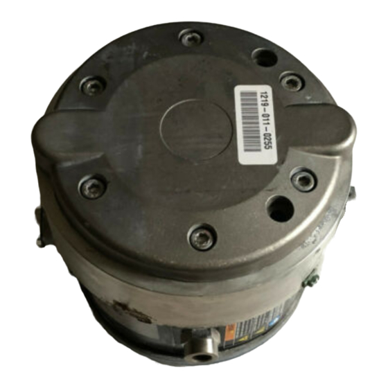
Triton
Diaphragm Pump
Used to pump waterborne and solvent-based paints and catalysts.
Part No. 253704, Series B
3:1 Ratio Air-operated Double Diaphragm Pump, with BSPP Fittings
Part No. 253705, Series B
3:1 Ratio Air-operated Double Diaphragm Pump, with NPT Fittings
100 psi (0.7 MPa, 7 bar) Maximum Air Input Pressure
300 psi (2.1 MPa, 21 bar) Maximum Fluid Working Pressure
Important Safety Instructions
Read all warnings and instructions in this manual.
Save these instructions.
Graco Inc. P.O. Box 1441 Minneapolis, MN 55440-1441
Copyright 2006, Graco Inc. is registered to I.S. EN ISO 9001
3D150
TI2125A
II 2 G
311688D
Advertisement
Table of Contents

Related Manuals for Graco TRITON 3D150


Summary of Contents for Graco TRITON 3D150
- Page 1 300 psi (2.1 MPa, 21 bar) Maximum Fluid Working Pressure Important Safety Instructions Read all warnings and instructions in this manual. Save these instructions. Graco Inc. P.O. Box 1441 Minneapolis, MN 55440-1441 Copyright 2006, Graco Inc. is registered to I.S. EN ISO 9001 311688D TI2125A II 2 G...
-
Page 2: Table Of Contents
Graco Standard Warranty ....28 Graco Information ......28... -
Page 3: Warning
Read all instruction manuals, tags, and labels before operating the equipment. • Use the equipment only for its intended purpose. If you are not sure, call your Graco distributor. • Do not alter or modify this equipment. Use only genuine Graco parts and accessories. - Page 4 TOXIC FLUID HAZARD Hazardous fluid or toxic fumes can cause serious injury or death if splashed in the eyes or on the skin, inhaled, or swallowed. • Know the specific hazards of the fluid you are using. • Store hazardous fluid in an approved container. Dispose of hazardous fluid according to all local, state and national guidelines.
-
Page 5: Installation
• Always use Genuine Graco Parts and Accessories, available from your Graco distributor. If you supply your own accessories, be sure they are adequately sized and pressure-rated for your system. •... -
Page 6: Mounting The Pump
Mounting the Pump • For ease of operation and service, mount the pump so the air inlet, fluid inlet, and fluid outlet ports are easily accessible. • Mount the pump in a well-ventilated area with suffi- cient clearance on all sides for operator access and servicing. -
Page 7: Air Line
Installation Air Line 1. Install the air line accessories as shown in F Be sure the air line supplying the accessories is grounded. a. The fluid pressure can be controlled with either an air regulator (F) to control the air into the pump, or with a fluid regulator (H) to control the fluid out of the pump. - Page 8 Key: TRITON 3D150 Pump Bleed-type master air valve (required for pump) Air supply line Air line filter Air line shutoff valve Pump air regulator Gun air regulator (used in spray system only) Fluid pressure regulator (used in spray system only)
-
Page 9: Grounding
Installation Grounding Before operating the pump, ground the system as explained below. Read the warnings on page 3. Ground all of this equipment: • Pump: use a ground wire and clamp. See F Loosen the grounding screw (X). Insert one end of a 12 ga (1.5 mm ) minimum ground wire (Y) under the clamp and tighten the screw securely. -
Page 10: Operation
Operation Pressure Relief Procedure Read the warnings on page 3, and follow the Pres- sure Relief procedure below whenever you: • are instructed to relieve pressure • stop spraying • check or service any of the equipment • install or clean the fluid nozzle. 1. -
Page 11: Maintenance
Maintenance Maintenance Lubrication CAUTION Lubrication of the pump is not required. Oil is exhausted through the muffler, which could contami- nate the fluid supply or other equipment. Excessive lubrication can also cause the pump to malfunction. Flushing and Storage Flush the pump often enough to prevent the fluid you are pumping from curing, drying, or freezing in the pump and damaging it. -
Page 12: Troubleshooting
Troubleshooting Relieve the pressure (page 10) before checking or servicing the equipment. Problem Pump cycles at stall or fails to hold pressure at stall. Pump will not cycle, or cycles once and stops. Pump operates erratically. Air bubbles in fluid. Pump running irregularly. -
Page 13: Repair
A qualified technician should make all repairs. • Inspect and clean all parts thoroughly before reassembly. • Use only genuine Graco replacement parts, available from your Graco distributor. • Be careful not to damage sealing surfaces. • Replace all o-rings removed from the pump. -
Page 14: Replace The Diaphragms
Replace the Diaphragms Wear gloves when removing or assembling the dia- phragms to reduce the risk of cuts. Diaphragm Repair Kit 246011 is available. Parts included in the kit are marked, for example (9*). For the best results, replace both diaphragms. Always replace the ball check seals (29) when- ever the fluid covers are removed. - Page 15 Repair Torque to 16 N•m (12 ft-lb). Housing Side 9* †‡◆ †‡◆ . 4 Replace the Diaphragms 311688D †‡◆ †‡◆ Cylinder Side 9*...
-
Page 16: Repair The Air Valve
Repair the Air Valve Air Valve Repair Kit 245066 is available. Parts included in the kit are marked, for example (33†). For the best results, use all parts in the kit. Disassembly 1. Prepare the pump for repair, page 13. 2. - Page 17 Repair 11† ◆ 11† ◆ 13† ◆ . 5. Repair the Air Valve 311688D Lubricate. Torque to 3.1 N•m (28 in-lb) Align arrow on housing with point on air valve plate. 13† ◆ 15† 17† ◆ 18† ◆ 16† 19† ◆...
-
Page 18: Repair The Shaft And Bearings
Repair the Shaft and Bearings Parts marked with a (♦) are included in Shaft repair kit 233841. For the best results, use all parts in the repair kit. Parts marked with a (❖) are included in Bearing repair kit 15J647. Disassembly 1. - Page 19 Repair Lubricate. Torque to 12 ft-lb (16 N•m) Align arrow on housing with point on air valve plate. Torque to 28 in-lb (3.1 N•m) ❖ †‡◆29 ❖ †◆11 †◆11 ❖ ◆ †‡◆ ❖ †◆ ◆ . 6. Repair the Shaft 311688D ❖...
-
Page 20: Replace The Ball Check Valves
Replace the Ball Check Valves Ball Check Valve Repair Kit 245067 is available. Parts included in the kit are marked with a (‡). For the best results, use all parts in the kit. Disassembly 1. Remove fluid covers (see page 13). Do not remove housing (54). - Page 21 Repair Torque to 12 ft-lb (16 N•m) Align ‡29 ‡28 ‡26 ‡32 Outlet Ball Checks ‡32 ‡26 ‡28 ‡29 . 7. Replace the Ball Check Valves 311688D ‡ ‡ ‡ ‡ ‡✖ Inlet Ball Checks ‡✖ ‡ ‡ ‡ ‡ ti2128B...
-
Page 22: Parts
Parts Part No. 253704, Series B Part No. 253705, Series B ❖42 ◆❖ †◆ †◆ ‡ ◆❖ ‡ ❖42 ‡ ‡ †‡◆ ♦8 †‡◆ ‡ ‡ ‡ ‡✖ 3❖ 43❖ † 1★ 43❖ †◆ †◆ 3❖ † ◆ ◆❖ ❖42 †◆... - Page 23 Parts Part No. 253704 BSPP, Series B Part No. 253705 NPT, Series B Ref. Part No. Description ★ HOUSING, diaphragm ◆❖ O-RING ❖ BEARING 117158 O-RING 197645 CARRIAGE, valve 15A289 CLAMP, sleeve ◆ SHAFT, pump, diaphragm ◆ O-RING DIAPHRAGM 197649 CARRIAGE †◆...
-
Page 24: Technical Data
Technical Data Category Maximum fluid working pressure Maximum air input pressure Ratio Maximum permissible stroke frequency in cycles/min Volume per cycle (double stroke) Operating temperature range Dry suction lift Wet suction lift Air inlet size Fluid inlet size Fluid outlet size Weight (approximate) Wetted parts Sound Pressure Levels in dB(A) at 50 cpm (measured at 1 meter from unit) -
Page 25: Performance Chart
Performance Chart Performance Chart Triton performance test, 40, 70, 100 psi (.27, .48, .69 MPa; 2.7, 4.8, 6.9 bar) 100 psi (.69 MPa, 6.9 bar) 70 psi (.48 MPa, 4.8 bar) 40 psi (.27 MPa, 2.7 bar) 311688D Cycles per minute Outlet Flow in gallons per minute 100 psi 70 psi... -
Page 26: Dimensions
Dimensions 66 mm (2.6 in.) 184 mm (7.2 in.) Fluid Outlet; 253705 3/8 npt 253704 3/8 BSPP 234 mm (9.2 in.) Fluid Inlet; 253705 3/4 npt 253704 M26x1.5 104 mm (4.1 in.) TI2133A 1 Dimensions 102 mm (4.0 in.) Air Inlet 253705 1/4 npt 253704 3/8 BSPP 9 mm (0.35 in.) - Page 27 Dimensions 311688D...
-
Page 28: Graco Standard Warranty
With the exception of any special, extended, or limited warranty published by Graco, Graco will, for a period of twelve months from the date of sale, repair or replace any part of the equipment determined by Graco to be defective.
Need help?
Do you have a question about the TRITON 3D150 and is the answer not in the manual?
Questions and answers