Table of Contents
Advertisement
Operation, Repair, and Parts
EcoQuip 2™
2™ Vapor
EcoQuip
EcoQuip
2™
System
System
System
Vapor abrasive
abrasive blast
blast system
Vapor
Vapor
abrasive
blast
Important
Important Safety
Important
Safety Instructions
Safety
Read all warnings and instructions in this manual. Save these
instructions.
175 psi (12.06 bar, 1.2 MPa) Maximum
Working Pressure
See page 3 for Models and approval
information.
Vapor Abrasive
Abrasive Blast
Vapor
Abrasive
system for
for coating
coating removal
removal and
system
for
coating
removal
Instructions
Instructions
PROVEN QUALITY. LEADING TECHNOLOGY.
Blast
Blast
and surface
surface preparation.
preparation. For
and
surface
preparation.
3A3489E
For professional
professional use
use only.
For
professional
use
EN
only.
only.
Advertisement
Table of Contents

Related Manuals for Graco EcoQuip 2


Summary of Contents for Graco EcoQuip 2
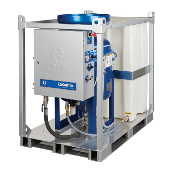
- Page 1 Operation, Repair, and Parts EcoQuip 2™ 2™ Vapor Vapor Abrasive Abrasive Blast Blast EcoQuip EcoQuip 2™ Vapor Abrasive Blast 3A3489E System System System Vapor abrasive abrasive blast blast system system for for coating coating removal removal and and surface surface preparation.
-
Page 2: Table Of Contents
Tubing Schematic..........63 Draining the Pot ........... 22 Winterizing the Equipment ......23 Dimensions ............64 Cleaning the Water Tank ......24 Technical Specifications........67 Using the Water Dose Meter......24 Notes..............73 Troubleshooting..........25 Repair..............30 Graco Standard Warranty........74 3A3489E... -
Page 3: Models
Models Models Models Models EcoQuip2 Vapor Vapor Blast Blast System System EcoQuip2 EcoQuip2 Vapor Blast System Blast Control Control Blast Blast Control Model Part Nozzle ATEX Model Model Part Part Nozzle Nozzle ATEX ATEX Pneumatic Electric Pneumatic Pneumatic Electric Electric 262950 262952* #7 Standard... -
Page 4: Related Manuals
Related Manuals Related Manuals Manuals Related Related Manuals Manual Number Number Product Manual Manual Number Product Product 313840 DataTrak™ 333397 Pump 335035 Air Inlet Kit 309474 Water Pressure Regulator 3A3470 Hose Rack Kit 3A3838 Nozzle Pressure Verification Kit 3A3839 Nozzle Extension Handle Kit 3A3970 Water Dose Kit 3A3971... -
Page 5: Warnings
Warnings Warnings Warnings Warnings The following warnings are for the setup, use, grounding, maintenance, and repair of this equipment. The exclamation point symbol alerts you to a general warning and the hazard symbols refer to procedure-specific risks. When these symbols appear in the body of this manual or on warning labels, refer back to these Warnings. - Page 6 Warnings WARNING WARNING WARNING EQUIPMENT MISUSE MISUSE HAZARD HAZARD EQUIPMENT EQUIPMENT MISUSE HAZARD Misuse can cause death or serious injury. • Do not operate the unit when fatigued or under the influence of drugs or alcohol. • Do not exceed the maximum working pressure or temperature rating of the lowest rated Technical Specifications Specifications in all equipment manuals.
- Page 7 Warnings WARNING WARNING WARNING MOVING PARTS PARTS HAZARD HAZARD MOVING MOVING PARTS HAZARD Moving parts can pinch, cut or amputate fingers and other body parts. • Keep clear of moving parts. • Do not operate equipment with protective guards or covers removed. •...
-
Page 8: System Component Identification
System Component Identification System Component Component Identification Identification System System Component Identification 3A3489E... -
Page 9: Mediatrak Controls
System Component Identification Key: Key: Key: Key: Key: Key: Frame Water Pump Inlet Filter Blast Control Switch Blast Air Pressure Gauge Blast Nozzle Selector Valve Blast Hose Rinse Ball Valve Air Supply Connection Pop-up Handle Blast Connection Water Tank Pneumatic Control Connection Water Tank Lid Electric Control Connection (non-ATEX systems only) -
Page 10: Pressure Relief Procedure
Systems: (237686). Air and and fluid fluid hoses: hoses: Use only genuine Graco fluid hoses: conductive blast hoses with a maximum of 150 ft (45 m) combined blast hose length to ensure grounding continuity. Check the electrical resistance of the blast hoses. -
Page 11: Operation
Operation Operation Operation Operation Lifting the the System System Blast Hose Hose Selection Selection Lifting Lifting System Blast Blast Hose Selection • Lift the system with a lift apparatus rated Make sure to use the correct type of blast control. An appropriately for the weight of the system electric or pneumatic blast control switch can be used (see... -
Page 12: Hose
Operation Connecting the the Blast Blast Hose Hose and and Air Connecting Connecting Blast Hose 3. Connect an appropriately sized air supply hose to the air inlet and install coupler pins. See Hose Hose Hose Technical Specifications, page 1. ATEX ATEX models ATEX models only:... -
Page 13: Eqs2 Elite Only)
Operation Connecting the the Water Water Hose Hose Connecting Connecting Water Hose 5. Connect the blast hose, hose restraints, control hoses, and coupler pins. (EQm and and EQs2 EQs2 Elite Elite only) only) (EQm (EQm EQs2 Elite only) 1. Connect to a water supply hose with a minimum ID of 3/4 in. -
Page 14: Setting Up The Equipment
Operation Setting Up Up the the Equipment Equipment Setting Setting Equipment 4. Disengage the emergency stop (Q). 1. Fill the water tank with fresh water only, then open the inlet ball valve (N). NOTE: The water pump will not work unless the NOTE: NOTE: Emergency Stop is disengaged. - Page 15 Operation 7. Add 10 gallons (30 liters) of fresh water 11. Turn the selector valve to BLAST. to the pot. Add abrasive material (see Technical Specifications, page 67 for capacity information). 12. Engage the blast control switch and set the blast air pressure to a maximum of 175 psi (12.06 bar, 1.2 MPa).
-
Page 16: Eqs2 Elite Blast Pressure Setting
Operation EQs2 Elite Elite Blast Blast Pressure Pressure Setting Setting EQs2 EQs2 Elite Blast Pressure Setting 14. To set the MediaTrak (ZD), slowly adjust the abrasive metering valve (T) while the abrasive is blasting from the nozzle to reach the desired 1. -
Page 17: Setting The Abrasive Metering Valve
Operation Setting the the Abrasive Abrasive Metering Metering Valve Valve Optimizing the the Abrasive Abrasive Metering Metering Setting Setting Abrasive Metering Valve Optimizing Optimizing Abrasive Metering Valve Valve Valve The optimal set point of the abrasive metering valve and corresponding MediaTrak CPM value varies To optimize performance, use the High Production or significantly depending on application and user Media Efficient lines on the charts. - Page 18 Operation General General General Application Application Guides: Application Guides: Guides: General Application Guide (Steel) Steel Typical Setting High Production Media Efficient Blast Pressure (psi) General Application Guide (Concrete/Masonry) Concrete/Masonry Typical Setting High Production Media Efficient Blast Pressure (psi) General Application Guide (Fiberglass) Fiberglass Typical Setting High Production...
-
Page 19: Nozzle Selection Guide
Operation Nozzle Selection Selection Guide Guide Nozzle Nozzle Selection Guide Use the Blast Blast Blast Pressure Pressure Pressure vs. vs. Air Air Flow Flow Flow Guide Guide Guide below to determine which nozzle to use to achieve the desired blast pressure based on compressor output. -
Page 20: Using The Wash Feature
Operation Using the the Wash Wash Feature Feature Using Using Wash Feature 1. Close the abrasive ball valve (M). The wash feature uses water (without abrasive) to rinse areas that have been blasted with abrasive. It is also a convenient feature for flushing abrasive from the blast hose. -
Page 21: Refilling The Pot With Abrasive
Operation Refilling the the Pot Pot with with Abrasive Abrasive Refilling Refilling with Abrasive 4. Engage the pop-up pin by compressing the spring and turning the handle 90° to hold the pop-up in the open position. 1. Close the abrasive ball valve (M). 5. -
Page 22: Draining The Pot
Operation Draining the the Pot Draining Draining 5. Place a bucket under the abrasive hose. Slowly open and close the abrasive ball valve to flush abrasive material from the pot. Repeat several times. Once no abrasive material flows from the hose, close the abrasive ball valve. -
Page 23: Winterizing The Equipment
Operation Winterizing the the Equipment Equipment Winterizing Winterizing Equipment 5. Turn the selector valve to WASH and open the rinse ball valve. While holding the rinse hose over the pot, run the pump until windshield wash comes out of the rinse hose. NOTICE NOTICE NOTICE... -
Page 24: Cleaning The Water Tank
Operation Cleaning the the Water Water Tank Tank Cleaning Cleaning Water Tank 5. Remove the tank lid and clean out with pressure washer. 1. Perform Pressure Relief Procedure, page 2. Disconnect the water inlet hose. Using the the Water Water Dose Dose Meter Meter Using... -
Page 25: Troubleshooting
Troubleshooting Troubleshooting Troubleshooting Troubleshooting Problem Problem Problem Cause Cause Cause Solution Solution Solution Unable to fill or The emergency stop (Q) is Disengage the emergency stop (Q). pressurize the pot engaged. with water. The air supply is inadequate. Make sure the air compressor is capable of supplying the minimum air flow requirement for your system (see Technical Specifications, page 67). - Page 26 Troubleshooting Problem Cause Solution Problem Problem Cause Cause Solution Solution The pot pressure relief The water pressure regulator Adjust the water pressure regulator to 185 psi (12.75 bar, valve is discharging is malfunctioning. 1.275 MPa). If this adjustment is not possible, service the water.
- Page 27 Troubleshooting Problem Cause Solution Problem Problem Cause Cause Solution Solution While in BLAST mode, The abrasive ball valve is Setting Up the Equipment, page with the blast control closed. switch (B) engaged, The abrasive metering valve Setting Up the Equipment, page air is flowing from the is not properly set.
- Page 28 Troubleshooting Problem Cause Solution Problem Problem Cause Cause Solution Solution While the blast control The supply air pressure is Make sure the compressor meets minimum flow switch (B) is engaged, fluctuating requirements and is operating properly. See the blast air flow is Technical Specifications, page 67 for more information on fluctuating.
- Page 29 Troubleshooting Problem Cause Solution Problem Problem Cause Cause Solution Solution Too much water is The water dose valve (S) Close the water dose valve (S). coming from the nozzle open too far. in BLAST mode. The abrasive material is too If possible, use at least 20 mesh abrasive material.
-
Page 30: Repair
HAZARD To reduce the risk of fire and explosion, the battery must be replaced in a non-hazardous location. Use only an approved replacement battery (see table). Use of an unapproved battery will void Graco’s warranty. Replace Replace Replace Battery Battery Battery 1. -
Page 31: Replacing The Datatrak Fuse
HAZARD HAZARD To reduce the risk of fire and explosion, the fuse must be replaced in a non-hazardous location. Use only an approved replacement fuse (see table). Use of an unapproved fuse will void Graco’s warranty. Replace Replace Fuse Replace... -
Page 32: Replacing The Pinch Hose
Repair Replacing the the Pinch Pinch Hose Hose Replacing Replacing Pinch Hose Removing Removing Removing the the Pinch Pinch Pinch Hose Hose Hose Installing Installing the Installing the Pinch Pinch Pinch Hose Hose Hose 1. Place both hose clamps (C1, C2) on the pinch hose (PH). -
Page 33: Notes
Notes Notes Notes Notes 3A3489E... -
Page 34: Parts
Parts Parts Parts Parts EQm Parts Parts Parts Apply thread sealant to all non-swivel pipe Apply anti-seize to enclosure mounting threads. studs. Apply anti-seize to threads. Torque to 25–30 ft-lb (34–40.6 N•m) The handway gasket must be installed Torque to 60 +/-5 ft-lb (81.3 +/- 6.7 N•m) with pot pressurized. - Page 35 Parts EQm Parts Parts List Parts List List Ref. Ref. Ref. Part Part Part Description Description Description Qty. Qty. Qty. Ref. Ref. Ref. Part Part Part Description Description Description Qty. Qty. Qty. - - - - - PRESSURE POT, blast media, EQ1051 GASKET, blast nozzle 3.5 cu ft.
-
Page 36: Eqs Parts
Parts EQs Parts Parts Parts 1. Apply thread sealant to all non-swivel pipe threads. Apply anti-seize to threads. Torque to 15 +/-2 ft-lb (20.3 +/- 2.7 N•m) 3A3489E... - Page 37 Parts EQs Parts Parts List Parts List List Ref. Ref. Ref. Part Part Part Description Description Description Qty. Qty. Qty. Ref. Ref. Ref. Part Part Part Description Description Description Qty. Qty. Qty. - - - - - - - - - - BASE, standard, frame, tank LABEL, brand, EcoQuip - - - - -...
- Page 38 Parts EQs (continued) (continued) (continued) Apply thread sealant to all non-swivel pipe Torque to 15 +/-2 ft-lb (20.3 +/- 2.7 N•m) threads. Apply anaerobic sealant to threads. Apply anti-seize to threads. The handway gasket must be assembled Torque to 60 +/-5 ft-lb (81.3 +/- 6.7 N•m) centered and flat on the handway cover.
- Page 39 FITTING, bushing lg, EcoQuip 2 - - - - - 1gg† VALVE, body, float, 1/2 17L639◊ BRACKET, painted, tank, lg, EcoQuip 2 - - - - - 1hh† ROD, float, 8 in. 17L637■ BRACKET, sst, tank, - - - - - 1kk†...
-
Page 40: Eqs2 Parts
Parts EQs2 Parts Parts EQs2 EQs2 Parts 1. Apply thread sealant to all non-swivel pipe threads. 3A3489E... - Page 41 Part Description Description Qty. Qty. - - - - - 17K875 FRAME, EcoQuip 2, dual HOSE, air, dual system, short 17K026 COVER, media, fill 17K876 HOSE, air, dual system, long - - - - - - - - - - 5†...
- Page 42 Parts EQs2 EQs2 EQs2 (continued) (continued) (continued) 1. Apply thread sealant to all non-swivel pipe Apply anti-seize to enclosure mounting threads. studs. Apply anti-seize to threads. Torque to 25–30 ft-lb (34–40.6 N•m). Torque to 60 +/-5 ft-lb (81.3 +/- 6.7 N•m) The handway gasket must be assembled centered and flat on the handway cover.
- Page 43 Parts EQs2 EQs2 EQs2 Parts Parts Parts List List (continued) List (continued) (continued) Ref. Part Description Qty. Ref. Part Description Qty. Ref. Ref. Part Part Description Description Qty. Qty. Ref. Ref. Part Part Description Description Qty. Qty. - - - - - 17L311 PRESSURE POT, blast media, SEAL, pop up, machined...
-
Page 44: Eqc And Eq200T / Eq400T Models
Parts EQc and and EQ200T EQ200T / / / EQ400T EQ400T Models Models EQ200T EQ400T Models 1. Apply thread sealant to all non-swivel pipe Apply anti-seize to enclosure mounting threads. studs. Apply anti-seize to threads. Torque to 25–30 ft-lb (34–40.6 N•m) Torque to 60 +/-5 ft-lb (81.3 +/- 6.7 N•m) The handway gasket must be assembled with pot pressurized. - Page 45 Parts EQc and and EQ200T EQ200T EQ200T / / / EQ400T EQ400T Parts EQ400T Parts List Parts List List Ref. Part Description Qty. Ref. Part Description Qty. Ref. Ref. Part Part Description Description Qty. Qty. Ref. Ref. Part Part Description Description Qty.
-
Page 46: Eq200T Parts
Parts EQ200T Parts Parts EQ200T EQ200T Parts Apply thread sealant to all non-swivel pipe threads. 3A3489E... - Page 47 NUT, lock, nylon 17J290 LABEL, instructions insert, 1/2, sst EQ1003 VALVE, ball, 3/4 npt, NOTE: For information regarding KAESER compressors or compressor engines see the KAESER compressor NOTE: NOTE: manual, which is included with EcoQuip 2 Trailer Systems (or visit us.kaeser.com). 3A3489E...
-
Page 48: Eq400T Parts
Parts EQ400T Parts Parts EQ400T EQ400T Parts Apply thread sealant to all non-swivel pipe threads. 3A3489E... - Page 49 LABEL, instruction 1/2, sst EQ1003 VALVE, ball, 3/4 npt, sst NOTE: For information regarding the Atlas Copco compressor or compressor engine see the Atlas Copco NOTE: NOTE: compressor manual, which is included with EcoQuip 2 Trailer Systems (or visit www.atlascopco.com). 3A3489E...
-
Page 50: Enclosure Box Parts
Parts Enclosure Box Box Parts Parts Enclosure Enclosure Parts Enclosure Enclosure Enclosure Parts Parts Parts Torque fitting with pump outlet fitting to 35–40 ft-lb (47.4–54.2 N•m) Apply thread sealant to needle valve knob screw when reassembling. Align knob with ‘D’ facing up when in closed position. Apply thread sealant to selector valve handle set screw when reassembling. - Page 51 Parts Ref. Part Description Qty. Ref. Part Description Qty. Ref. Ref. Part Part Description Description Qty. Qty. Ref. Ref. Part Part Description Description Qty. Qty. ▲ 17L807 LABEL, notice 112268 SWIVEL, union - - - - - 17L324 BRACKET, pump REGULATOR, pressure, water, 185 psi (includes 25A531...
- Page 52 Parts Enclosure Enclosure Enclosure Parts Parts Parts (continued) (continued) (continued) Apply thread sealant to emergency stop valve stem when reassembling the red knob. 3A3489E...
- Page 53 Parts Ref. Ref. Ref. Part Part Part Description Description Description Qty. Qty. Qty. Ref. Ref. Ref. Part Part Part Description Description Description Qty. Qty. Qty. - - - - - VALVE, 3-way. e-stop, 3/8 BRACKET, EcoQuip, EQ5108 DataTrak in. fpt 3 17K057 ENCLOSURE, DataTrak, EQ1438...
- Page 54 Parts Enclosure Enclosure Enclosure Parts Parts (All Parts (All models (All models except models except except EQm) EQm) EQm) Assemble valve (17) with plunger facing the Apply anti-seize to threads on clamp (60). bent manifold (16). Align the nuts pointing towards the front of the enclosure.
- Page 55 Parts Ref. Part Description Qty. Ref. Part Description Qty. Ref. Ref. Part Part Description Description Qty. Qty. Ref. Ref. Part Part Description Description Qty. Qty. 17K052 VALVE, pinch 17F436 MANIFOLD, blast circuit, 1.5, bottom - - - - - SEAL, wiper 680454 GASKET, sanitary fitting - - - - -...
- Page 56 Parts Enclosure Enclosure Enclosure Parts Parts Parts (EQm (EQm (EQm only) only) only) Assemble valve (17) with plunger facing the Apply anti-seize to threads on clamp (60). bent manifold (16). Align the nuts pointing towards the front of the enclosure. Torque nuts to 15 +/- 2 ft-lb (20.3 +/- 2.7 N•m) Apply anti-seize to threads on clamp (62).
- Page 57 Parts Ref. Part Description Qty. Ref. Part Description Qty. Ref. Ref. Part Part Description Description Qty. Qty. Ref. Ref. Part Part Description Description Qty. Qty. 17K052 VALVE, pinch 17G578 MANIFOLD, blast circuit, 1.0, bottom - - - - - SEAL, wiper 680454 GASKET, sanitary fitting - - - - -...
-
Page 58: Blast Hoses
Parts Blast Hoses Hoses Blast Blast Hoses Electric, 50 50 ft ft ft Electric, Electric, Ref. Part Description Qty. Ref. Ref. Part Part Description Description Qty. Qty. 26A024 26A024 26A024 (1.25 (1.25 (1.25 in.), in.), in.), 26A074 26A074 26A074 (1.0 (1.0 (1.0 in.) in.) -
Page 59: Vapor Abrasive Blast Systems And Accessories
Vapor Abrasive Blast Systems and Accessories Vapor Abrasive Abrasive Blast Blast Systems Systems and and Accessories Accessories Vapor Vapor Abrasive Blast Systems Accessories Blast Hoses Hoses with with Control Control Hose/Cable Hose/Cable Blast Blast Hoses with Control Hose/Cable Part Part Part ID ID ID Blast... -
Page 60: Eq200T (M58 Kaeser Compressor)
Vapor Abrasive Blast Systems and Accessories EQ200T (M58 (M58 Kaeser Kaeser Compressor) Compressor) EQ200T EQ200T (M58 Kaeser Compressor) Part Description Part Part Description Description 129219 KIT, fluid, separator, M57/M58 129221 KIT, air inlet filter, M57/M58 129223 KIT, fluid filter, M57/M58/M100 129226 KIT, ENG, in-line fuel, M57/M100 129227... -
Page 61: Other Accessories
Vapor Abrasive Blast Systems and Accessories Other Accessories Accessories Other Other Accessories Part Description Part Part Description Description 17L119 Kit, nozzle gasket (pack of 5) EQ5166 Kit, nozzle extension, 24 in (0.6 m) 26A029 Kit, nozzle extension, 24 in (0.6 m), with handles 17J958 Kit, nozzle pressure verification tool 17G833... -
Page 62: Common Spare Parts
Vapor Abrasive Blast Systems and Accessories Common Spare Spare Parts Parts Common Common Spare Parts Part Description Part Part Description Description 17D786 Hose restraint / Whip check 17D787 Blast hose coupler pin kit (6 pack) 17C124 Grommet, hose coupler. Fits either 1.0 in. or 1.25 in. dia. hose 17L309 Gasket, abrasive hose cam lock (10 pack) 17L119... -
Page 63: Tubing Schematic
Tubing Schematic Tubing Schematic Schematic Tubing Tubing Schematic Cut Length Length Length inches inches inches (mm) (mm) (mm) Part Ref. Ref. Ref. Part Part Color, Color, Color, Tube Tube Size Tube Size Size EQ2M EQ2M EQ2M EQ2S EQ2S EQ2S EQ2S EQ2S EQ2S Elite Elite... -
Page 64: Dimensions
Dimensions Dimensions Dimensions Dimensions EQm Models: Models: Models: EQs and and EQs EQs Elite Elite Models: Elite Models: Models: 3A3489E... - Page 65 Dimensions EQs2 Elite Elite Models: Models: EQs2 EQs2 Elite Models: EQc Models: Models: Models: 3A3489E...
- Page 66 Dimensions EQ Trailer Trailer Models: Models: Trailer Models: EQ200T EQ200T EQ200T EQ400T EQ400T EQ400T 3A3489E...
-
Page 67: Technical Specifications
* Abrasive capacity and wet weight was found using 80 grit garnet. Using coarser media or less dense media will decrease weight. † 2 in. ground boss adapter included in tool box (see Parts section of the EcoQuip 2 manual for more detail). Air Supply Hose Minimum ID 185–600 CFM compressor and less than 100 ft. - Page 68 * Abrasive capacity and wet weight was found using 80 grit garnet. Using coarser media or less dense media will decrease weight. † 2 in. ground boss adapter included in tool box (see the Parts section of the EcoQuip 2 manual for more detail).
- Page 69 * Abrasive capacity and wet weight was found using 80 grit garnet. Using coarser media or less dense media will decrease weight. † 2 in. ground boss adapter included in tool box (see Parts section of the EcoQuip 2 manual for more detail). Air Supply Hose Minimum ID 185–600 CFM compressor and less than 100 ft.
- Page 70 * Abrasive capacity and wet weight was found using 80 grit garnet. Using coarser media or less dense media will decrease weight. † 2 in. ground boss adapter included in tool box (see the Parts section of the EcoQuip 2 manual for more detail) Air Supply Hose Minimum ID 1.5 in.
- Page 71 Technical Specifications EQ200T Elite Elite EQ200T EQ200T Elite EcoQuip EcoQuip 2 2 2 EQ200T EcoQuip EQ200T EQ200T Elite Elite Elite U.S. U.S. U.S. Metric Metric Metric Maximum Working Pressure 100 psi 6.89 bar, 0.69 MPa Operating Temperature 35˚ - 110˚ F 1.6˚...
- Page 72 Technical Specifications EQ400T Elite Elite EQ400T EQ400T Elite EcoQuip EcoQuip 2 2 2 EQ400T EcoQuip EQ400T Elite EQ400T Elite Elite U.S. U.S. U.S. Metric Metric Metric Operating Temperature 35˚ - 110˚ F 1.6˚ - 43.3˚ C 1.25 in. ID 31.75 mm ID...
-
Page 73: Notes
Notes Notes Notes Notes 3A3489E... -
Page 74: Graco Standard Warranty
With the exception of any special, extended, or limited warranty published by Graco, Graco will, for a period of twelve months from the date of sale, repair or replace any part of the equipment determined by Graco to be defective. This warranty applies only when the equipment is installed, operated and maintained in accordance with Graco’s written recommendations.
Need help?
Do you have a question about the EcoQuip 2 and is the answer not in the manual?
Questions and answers