Table of Contents
Advertisement
Advertisement
Table of Contents

Subscribe to Our Youtube Channel
Related Manuals for MSA alpha Series


Summary of Contents for MSA alpha Series
- Page 1 Operating Manual AirMaXX® SL SCBA Basic Apparatus Order N°. 10075782/15...
- Page 2 MSA Europe GmbH Schlüsselstrasse 12 8645 Rapperswil-Jona Switzerland Product of Germany © MSA 2019. All rights reserved...
-
Page 3: Table Of Contents
CONTENTS Contents Safety Regulations ....................5 1.1. Correct Use ..................... 5 1.2. Liability Information ..................5 Description ....................... 6 2.1. Standard Model (AirMaXX SL) ................ 6 2.1.1. Pressure Reducer ................7 2.1.2. Manifold ....................7 2.1.3. SingleLine SCOUT ................8 2.2. - Page 4 CONTENTS 3.12. Removing the Compressed Air Breathing Apparatus ........24 3.13. Removing the Compressed Air Cylinders ............. 25 3.13.1. Pressure Reducer with Screw Coupling ........... 25 3.13.2. Pressure Reducer with alphaCLICK 2 ..........25 Maintenance and Care of the SCBA ..............27 4.1.
-
Page 5: Safety Regulations
Alternative use, or use outside this specifications will be considered as non- compliance. This also applies especially to unauthorised alterations to the apparatus and to commissioning work that has not been carried out by MSA or authorised persons. Danger! This product supports life and health. -
Page 6: Description
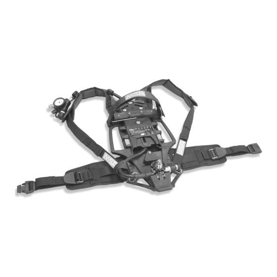
DESCRIPTION Description Fig. 1 AirMaxx SL compressed air breathing apparatus Manifold Handle Cylinder separator Catch clip Cylinder retaining strap Push lock Cylinder support Quick-Fill coupling (Option) Tension clamp Pressure reducer Shoulder strap Single line Back plate Hip belt 2.1. Standard Model (AirMaXX SL) The two-piece back plate of the compressed air breathing apparatus is adjustable to three different lengths and should be adjusted to the user's height. -
Page 7: Pressure Reducer
DESCRIPTION 2.1.1. Pressure Reducer Fig. 2 Pressure reducer Single line connection Compressed air cylinder connection Quick-Fill coupling (not for standard model) Lead seal The pressure reducer is mounted in the lower area of the back plate ( Fig. 2). On the pressure reducer, there is a relief valve and the single line for connecting the manifold. -
Page 8: Singleline Scout
DESCRIPTION 2.1.3. SingleLine SCOUT See additional manual SingleLine SCOUT. 2.2. Model AirMaXX SL-CLICK The difference between this model and the standard model is the modified pressure reducer, the constituent part of the alphaCLICK 2 coupling system. It is also available as the standard model and in the SL-M, SL-Q and eXXtreme SL versions. -
Page 9: Alphaclick 2 Coupling 300 Bar
DESCRIPTION 2.2.1. alphaCLICK 2 Coupling 300 bar Fig. 5 alphaCLICK 2 coupling 300 bar alphaCLICK 2 coupling 300 bar Indicator ring with arrow 2.2.2. alphaCLICK 2 Cylinder Adaptor 300 bar Fig. 6 alphaCLICK 2 cylinder adaptor 300 bar alphaCLICK 2 cylinder adaptor 300 bar The cylinder adaptor has to be screwed into a cylinder valve with a specific torque of 20-30 Nm. -
Page 10: Model Airmaxx Sl-M
DESCRIPTION 2.2.3. Model AirMaXX SL-M Besides the standard unit fittings, this model also comes with a built-in short range transmitter (alphaMITTER). This is assembled on the back plate of the compressed air breathing apparatus and connected via an additional line to the pressure reducer. -
Page 11: Models Airmaxx Sl-3C And Airmaxx Sl-3N
DESCRIPTION 2.3. Models AirMaXX SL-3C and AirMaXX SL-3N The versions AirMaXX SL-3C and AirMaXX SL-3N differ from the standard version in that they have an additional medium pressure connection. They are available as the standard model and in the SL-Q and eXXtreme SL versions. -
Page 12: Model Airmaxx Sl-Q
DESCRIPTION 2.4. Model AirMaXX SL-Q Besides the standard unit fittings, this model also comes with a high pressure safety coupling ( Pos. 3 in Fig. 2). It is then possible to fill 300 bar compressed air cylinder(s) whilst the compressed air breathing apparatus is in use. Warning! On compressed air breathing apparatus with Quick-Fill couplings, the use of 200 bar compressed air cylinders is not possible. -
Page 13: Technical Data
DESCRIPTION 2.6. Technical Data High pressure 200 bar resp. 300 bar Medium pressure 5 bar to 9 bar Operating -30°C to +60°C Weight (approx.) 3.7 kg Dimensions Length 575 mm Width 300 mm Height 135 mm Approvals The compressed air breathing apparatus conforms to Directive 89/686 EEC or Regulation (EU) 2016/425, respectively, and Directive 2014/34/EU. -
Page 14: Using The Compressed Air Breathing Apparatus
USING THE COMPRESSED AIR BREATHING APPARATUS Using the Compressed Air Breathing Apparatus Warning! The compressed air breathing apparatus may only be put into use in a fully maintained and tested condition. If malfunctions or defects are noticed prior to use, do not use the compressed air breathing apparatus under any circumstances. -
Page 15: Connecting One Compressed Air Cylinder
USING THE COMPRESSED AIR BREATHING APPARATUS Fig. 10 Compressed air breathing apparatus – details Cylinder separator Cylinder support Cylinder retaining strap Tension clamp 3.2.1.2. Connecting One Compressed Air Cylinder (1) Place compressed air breathing apparatus horizontally so that the back face is uppermost (... -
Page 16: Pressure Reducer With Alphaclick 2
• The screw coupling of the cylinder valve must be undamaged and free from dirt and debris. • If the cylinder valve is damaged, remove from service and return it to a MSA trained or certified repair technician. AirMaXX SL... -
Page 17: Connecting One Compressed Air Cylinder
USING THE COMPRESSED AIR BREATHING APPARATUS (2) Inspect the external couplings of the cylinder adaptor and the nipple of the male connector on the pressure reducer to ensure they are not damaged and free of dirt and debris. • Ensure that the O-ring is installed on the cylinder adaptor and it is undamaged and free of dirt and debris. - Page 18 USING THE COMPRESSED AIR BREATHING APPARATUS (4) Open tension clamp on the cylinder strap eliminating any tension by extending the strap to full length pulling the small bar at the tension clamp ( Fig. 11). (5) Push compressed air cylinder through the cylinder strap (2) with the cylinder valve toward the pressure reducer so that it lies on the central support (3).
-
Page 19: Connecting Two Compressed Air Cylinders
USING THE COMPRESSED AIR BREATHING APPARATUS 3.3. Connecting Two Compressed Air Cylinders 3.3.1. Pressure Reducer with Screw Coupling Fig. 14 SCBA apparatus with twin compressed air cylinders 3.3.1.1. Preparing the Apparatus for Use with Two Compressed Air Cylinders (1) Hinge up the cylinder separator to a vertical position in the middle of the cylinder support until it catches. -
Page 20: Pressure Reducer With Alphaclick 2
USING THE COMPRESSED AIR BREATHING APPARATUS (10) Briefly open cylinder valves and check for escaping air, retighten if necessary. (11) Tighten cylinder strap gently by pulling the free end. Attention! Do not overtighten the cylinder strap! Damage can occur when using excessive force to close the tension clamp and the SCBA might not be ready for use. -
Page 21: Adjusting The Back Plate
USING THE COMPRESSED AIR BREATHING APPARATUS (10) Close the coupling by pushing together using a "small amount" of force and checking that the arrow of the indicator ring is vertically aligned with the back plate. (11) Proceed as described from (11) to (14) for pressure reducer with screw coupling. -
Page 22: Condensed Check Prior To Use
USING THE COMPRESSED AIR BREATHING APPARATUS 3.6. Condensed Check Prior to Use (1) Open cylinder valve(s) and check pressure on the pressure gauge. The pressure values must read: for 300 bar cylinders: minimum 270 bar for 200 bar cylinders: minimum 180 bar (2) Close cylinder valve(s) and check pressure gauge. -
Page 23: Use Of The Second Connection
USING THE COMPRESSED AIR BREATHING APPARATUS 3.9. Use of the Second Connection (1) Remove safety cap from medium pressure coupling of Second Connection on the manifold. (2) Connect medium pressure line of lung governed demand valve of second user until the coupling audibly catches. Warning! When rescuing persons with the rescue set via the Second Connection, more air is consumed. -
Page 24: Filling With Quick-Fill
USING THE COMPRESSED AIR BREATHING APPARATUS 3.11. Filling with Quick-Fill Fig. 17 Fill with Quick-Fill (optional) Quick-Fill coupling With the Quick-fill function, the compressed air cylinder(s) of the breathing apparatus can be filled during use (see Operating Manual for Quick-Fill). 3.12. -
Page 25: Removing The Compressed Air Cylinders
USING THE COMPRESSED AIR BREATHING APPARATUS 3.13. Removing the Compressed Air Cylinders 3.13.1. Pressure Reducer with Screw Coupling (1) Place the compressed air breathing apparatus in a horizontal position with the cylinder facing up. (2) Hinge up tension clamp at cylinder strap ( Fig. 11) and thus loosen the strap. - Page 26 USING THE COMPRESSED AIR BREATHING APPARATUS (4) For compressed air cylinders with alphaCLICK 2 turn the handwheel on the coupling side (arrow 1) in a clockwise direction first ( Fig. 18) and then, when closed up to the stop, push downwards in the direction of the pressure reducer (arrow 2).
-
Page 27: Maintenance And Care Of The Scba
Always use original parts from MSA. Repairs and maintenance must be carried out only by authorised service centres or by MSA. Changes to devices or components are not permitted and could result in loss of approved status. -
Page 28: Maintenance Intervals
MAINTENANCE AND CARE OF THE SCBA 4.2. Maintenance Intervals 4.2.1. Test Intervals for all Countries (except Germany) Component Work to be Before After use Annually Every Every Performed 3 years 9 years Compressed air Cleaning breathing Sight, function and apparatus complete tightness check Check by user Compressed air... -
Page 29: Cleaning
MAINTENANCE AND CARE OF THE SCBA 4.3. Cleaning 4.3.1. Pre-cleaning (1) Open cylinder valve(s) of the mounted compressed air cylinder(s) fully. (2) Remove rough dirt from breathing apparatus with water hose. Here, we recommend using a mild detergent. (3) Close cylinder valve(s), release air from apparatus with lung governed demand valve. - Page 30 MAINTENANCE AND CARE OF THE SCBA (9) Push out the spindle (3) in the pressure reducer holder ( Fig. 19). (10) Remove pressure reducer from the back plate, do not push up the stop spring (2). Fig. 19 Remove pressure Fig.
-
Page 31: Instructions For Assembling The Pressure Reducer
MAINTENANCE AND CARE OF THE SCBA 4.4. Instructions for Assembling the Pressure Reducer Fig. 21 Back plate (from the rear) Fig. 22 Pressure reducer Line holder bracket Connection on the pressure reducer When assembling the pressure reducer (regardless of the model) on the back plate, ensure the correct setting of the single line (... -
Page 32: Warning Device Check
Visually check the sealing ring of the cylinder connector in the pressure reducer. Damaged sealing rings must be replaced. 4.8. Overhaul The overhaul of the pressure reducer may only be performed by MSA or an authorised service centre. Attention! Pressure reducers are completed with a lead seal. Where the lead seal is missing or damaged, it cannot be guaranteed that they are ready for use or that they correspond to the approval status. -
Page 33: Changing/Filling Of Compressed Air Cylinders To Alphaclick 2
CHANGING/FILLING OF COMPRESSED AIR CYLINDERS TO ALPHACLICK 2 Changing/Filling of Compressed Air Cylinders to alphaCLICK 2 5.1. Changing of Compressed Air Cylinders to alphaCLICK 2 All usual compressed air cylinders with standard valve threads [EN 144-2] can be easily equipped with the alphaCLICK 2 coupling system. This makes efficient use when combined with compressed air breathing apparatus of the type AirMaXX SL-CLICK and uses the advantages of the innovative coupling system. -
Page 34: Filling Of Compressed Air Cylinders With Alphaclick 2
CHANGING/FILLING OF COMPRESSED AIR CYLINDERS TO ALPHACLICK 2 5.2. Filling of Compressed Air Cylinders with alphaCLICK 2 Fig. 24 Filling station for compressed air cylinders with alphaCLICK 2 Compressed air cylinder with alphaCLICK 2 cylinder adaptor Operating lever Blind plug alphaCLICK 2 filling coupling Cylinder adaptor With the help of the filling panel, it is possible to fill several compressed air... - Page 35 CHANGING/FILLING OF COMPRESSED AIR CYLINDERS TO ALPHACLICK 2 (3) Attach the compressed air cylinder to the alphaCLICK 2 coupling and open the cylinder valve. Attention! When being pressurised, cylinder must not be swivelled as this can cause damage to the alphaCLICK 2 filling coupling. This is particularly important if a water basin for cooling is used while filling.
-
Page 36: Accessories
6.2. Lung Governed Demand Valve / Full Face Mask The base units of the AirMaXX SL series are provided for use with various MSA lung governed demand valves and full face masks. A list of compatible devices is given under Section 7.2... -
Page 37: Ordering Information
ORDERING INFORMATION Ordering Information 7.1. Compressed Air Cylinders Description Part No. Compressed Air Breathing Apperatus Basic Apparatus AirMaXX SL ATO code (assembly to order) 7.2. Lung Governed Demand Valve Description Part No. Normal Pressure AutoMaXX N 10023686 For facepieces from the 3S, Ultra Elite series Positive Pressure Standard Thread Connection M45X3 AutoMaXX AE 10023687... -
Page 38: Compressed Air Cylinders
ORDERING INFORMATION 7.3. Compressed Air Cylinders Description Part No. Compressed Air Cylinders, Steel 4 litre/200 bar, filled D5103965 4 litre/200 bar, empty D5103985 6 litre/300 bar, filled D5103967 6 litre/300 bar, empty D5103986 6 litre/300 bar, filled, with flow restrictor 10015960 6 litre/300 bar, filled, with ratchet valve 10024010... -
Page 39: Accessories
ORDERING INFORMATION 7.4. Accessories Description Part No. T-piece 115/200 bar, for two 4 litre/200 bar cylinders D4085817 T-piece 156/300, for two 300 bar Composite cylinders D4075818 Protective cover blue-black for composite cylinders D4075877 Protective cover yellow for Composite cylinders D4075878 Quick-Fill line, 1 metre D4075929 Quick-Fill cylinder adaptor... -
Page 40: Upgrading Options
(incl. alphaCLICK 2 coupling set 300 bar, pressure reducer, manifold & SingleLine in exchange for your old SCBA pneumatics Upgrade Set: alphaCLICK 2 300 bar In case you want to upgrade your existing MSA pneumatics with alphaCLICK 2. alphaCLICK 2 coupling set 300 bar... -
Page 41: Work Shop Accessories
ORDERING INFORMATION 7.6. Work Shop Accessories Description Part No. Open-ended 19 mm spanner for fitting the alphaCLICK to the pressure 10075231 reducer (for alphaCLICK 1 generation only) Control pressure gauge up to 400 bar cylinder pressure D4080929 Control pressure gauge (class 1.0) for pressure gauge check (400 bar) D5175825 Control pressure gauge (class 0.6) for pressure gauge check (400 bar) D5175867... - Page 42 NOTES Notes AirMaXX SL...
- Page 43 NOTES Notes AirMaXX SL...
- Page 44 For local MSA contacts, please visit us at MSAsafety.com Because every life has a purpose...
Need help?
Do you have a question about the alpha Series and is the answer not in the manual?
Questions and answers