
Related Manuals for Kichler Lighting 330163


Summary of Contents for Kichler Lighting 330163
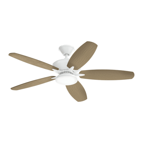
- Page 1 52" RENEW DESIGNER Product images may vary slightly from actual product. INSTRUCTION MANUAL UL Model #330163 REV 02-APR-2021 READ AND SAVE THESE INSTRUCTIONS...
- Page 2 Net weight: 7.70 kgs (16.98 lbs) Gross weight: 8.70 kgs (19.18 lbs)
-
Page 3: Table Of Contents
TABLE OF CONTENTS SAFETY RULES ATTACHING THE FAN BLADES CARE AND USE INSTRUCTIONS INSTALLING THE LED LIGHT KIT TOOLS AND MATERIALS REQUIRED INSTALLING THE GLASS SHADE PACKAGE CONTENTS INSTALLING THE BATTERY MOUNTING OPTIONS OPERATING INSTRUCTIONS HANGING THE FAN INSTALLING THE TRANSMITTER WALL BRACKET INSTALLATION OF SAFETY SUPPORT TROUBLESHOOTING ELECTRICAL CONNECTIONS... -
Page 4: Safety Rules
SAFETY RULES CAUTION -RISK OF SHOCK- 9. Avoid placing objects in the path of the blades. Disconnect Power at the main circuit breaker panel 10. To avoid personal injury or damage to the fan and other or main fusebox before starting and during the items, be cautious when working around or cleaning installation. -
Page 5: Care And Use Instructions
CARE AND USE INSTRUCTIONS Read and understand these Care and Use Instructions 6. Be sure the fixture is supported by a chain only (if and all installation instructions provided with this fixture hangs by chain) and not by wire. fixture, both front and back, before proceeding with The hand-crafted beauty of this fixture is the assembly, installation, care and use of this fixture. -
Page 6: Package Contents
TOOLS REQUIRED • Philips screw driver • Blade screw driver • 11mm wrench • Step ladder • Wire cutters PACKAGE CONTENTS Unpack your fan and check the contents. You should have the following items: A. Fan blades (5) K. Package hardware: B. -
Page 7: Mounting Options
MOUNTING OPTIONS If there is not an existing UL (cUL for Canadian Installation) listed mounting box, then read the following instructions. Disconnect the power by removing fuses or turning off circuit breakers. Outlet box Secure the outlet box directly to the building structure. Use appropriate fasteners and building materials. -
Page 8: Hanging The Fan
HANGING THE FAN cULus Listed REMEMBER to turn off the power before you begin. outlet box To properly install your ceiling fan, follow the steps below. NOTE: This ceiling fan is supplied with two types of hanging assemblies; the standard ceiling installation using the downrod with ball and socket mounting and the “close-to-ceiling”... - Page 9 Hanger ball HANGING THE MOTOR ASSEMBLY Cross pin Standard Ceiling Installation Step 1. Pass the 120-volt supply wires through the center hole in the Ceiling canopy ceiling hanger bracket as shown in Fig. 5. Decoration ring Step 2. Secure the hanger bracket to the ceiling outlet box with the screws and washers provided with your outlet box.
- Page 10 Screws and Lock HANGING THE MOTOR ASSEMBLY washers(3 of 6 places) Canopy Close-to-Ceiling Installation Step 1. Pass the 120-volt supply wires through the center hole in the ceiling hanger bracket as shown in Fig. 5. Decoration ring Step 2. Secure the hanger bracket to the ceiling outlet box with the Gasket screws and washers provided with your outlet box.
-
Page 11: Installation Of Safety Support
INSTALLATION OF SAFETY SUPPORT (Required for Canadian installation ONLY) A safety support cable is provided to help prevent the ceiling fan from falling, please install it as follows. Hanger bracket Step 1. Attach the provided wood screw to the ceiling joist next to the mounting bracket. - Page 12 ELECTRICAL CONNECTIONS Step 2. Motor to Receiver Electrical Connections: (Fig. 12) Connect the black wire from the fan to the black wire marked “TO MOTOR L” on the receiver. Connect the white wire from the fan to the white wire marked Outlet box in the ceiling “TO MOTOR N”...
-
Page 13: Finishing The Motor Installation
Ceiling mounting Screws & Washers FINISHING THE MOTOR INSTALLATION bracket Standard Ceiling Installation Decoration ring Step 1. Tuck all the connections neatly into the ceiling outlet box. Canopy Step 2. Slide the canopy up to ceiling and attach the canopy to the ceiling mounting bracket using 4 screws at the top edge of the mounting bracket. -
Page 14: Attaching The Fan Blades
Screw Washer ATTACHING THE FAN BLADES Blade arm Blade CAUTION: Remove the rubber shipping blocks attached to the face of the motor. These blocks keep the motor from shifting during shipping and MUST be removed during installation. Step 1. Attach the blade to the blade bracket using the screws and Fan motor washers as shown in Figure 15. -
Page 15: Installing The Glass Shade
INSTALLING THE GLASS SHADE Step 1. Raise the glass shade against the light kit and turn clockwise until snug, DO NOT OVERTIGHTEN. (Fig. 17) Light kit Glass shade Fig. 17 INSTALLING THE BATTERY Install a 9 volt battery included with the Hand Held Transmitter. (Fig. -
Page 16: Operating Instructions
OPERATING INSTRUCTIONS Turn the power on and check the operation of your ceiling fan. Fan Speed: These four buttons are used to set the fan speed as follows: LOW = low speed MED = medium speed HI = high speed OFF = turns fan off Light This button turns the light ON or OFF. -
Page 17: Installing The Transmitter Wall Bracket
INSTALLING THE TRANSMITTER Screws WALL BRACKET 1. Choose a location for the Transmitter Wall Pocket. Any location within 30 feet from the ceiling fan remote control receiver is required. Choose a flat location, using the wall pocket as a guide, mark the wall anchor locations. -
Page 18: Troubleshooting
TROUBLESHOOTING Problem Solution Fan will not start. Check circuit fuses or breakers. Check all electrical connections to ensure proper contact. CAUTION: Make sure the main power is OFF when checking any electrical connection. Fan sounds noisy. Make sure all motor housing screws are snug. Make sure the screws that attach the fan blade brackets to the motor are tight. -
Page 19: Ceiling And Wall Fan Warranty
What We Will Do Note: Some states/provinces (including Quebec) do not allow the exclusion or limitation Kichler Lighting, at its sole discretion, will repair or replace, free of charge, during the of special, incidental or consequential damages, so the below limitations and exclusions applicable warranty period, any product or component part (as described above) that may not apply to you. -
Page 20: Fcc Information
FCC INFORMATION This device complies with part 15 of the FCC Rules. Operation is subject to the following two conditions: 1. This device may not cause harmful interference, and 2. This device must accept any interference received, including interference that may cause undesired operation. Note: This equipment has been tested and found to comply with the limits for a Class B digital device, pursuant to part 15 of the FCC Rules. - Page 21 www.kichler.com KICHLER LIGHTING ® 7711 EAST PLEASANT VALLEY ROAD CLEVELAND, OHIO 44131-8010 CUSTOMER SERVICE 866.558.5706 8:00 AM TO 5:00 PM EST, MONDAY - FRIDAY 52" Renew Designer |...
- Page 22 RENEW DESIGNER, 132 CM Les images du produit peuvent varier légèrement par rapport au produit réel. MANUEL D'INSTRUCTIONS Renew Designer, 132 cm | Modèle UL nº 330163 LISEZ ET CONSERVEZ CES INSTRUCTIONS...
- Page 23 Poids net: 7,70 kgs (16,98 lbs) Poids brut: 8,70 kgs (19,18 lbs) | KICHLER.COM...
- Page 24 TABLE DES MATIÈRES RÈGLES DE SÉCURITÉ INSTALLATION DES PALES DU VENTILATEUR OUTILS ET ÉQUIPEMENT REQUIS INSTALLATION DU LUMINAIRE À DEL INSTRUCTIONS POUR L’ENTRETIENT INSTALLATION DE L’ABAT-JOUR EN VERRE ET L’UTILISATION INSTALLATION DE LA PILE CONTENU DE L’EMBALLAGE MODE D’EMPLOI OPTIONS D’INSTALLATION INSTALLATION DU SUPPORT DE TÉLÉCOMMANDE SUSPENSION DU VENTILATEUR DÉPANNAGE...
-
Page 25: Règles De Sécurité
RÈGLES DE SÉCURITÉ ATTENTION - RISQUE DE CHOC ÉLECTRIQUE - Ne placez pas d’objets dans la trajectoire des pales. Coupez le courant au panneau à disjoncteurs principal ou 10. Pour éviter les blessures corporelles ou les dommages à la boîte à fusibles principale avant d’entamer et pendant au ventilateur ou d’autres objets, faites preuve de prudence l’installation. -
Page 26: Instructions Pour L'entretient Et L'utilisation
INSTRUCTIONS POUR L’ENTRETIENT ET L’UTILISATION Lire attentivement et comprendre ces instructions d’entretien Ce très beau luminaire, fabriqué à la main, au design et d’utilisation ainsi que toutes les instructions d’installation particulièrement soigné est le résultat d’une collaboration fournies avec ce luminaire, recto et verso, avant de procéder étroite entre une vaste expertise en ingénierie, un travail au montage, à... -
Page 27: Contenu De L'emballage
OUTILS REQUIS • Tournevis cruciforme • Tournevis plat • Clé de 11 mm • Escabeau • Coupe-fils CONTENU DE L’EMBALLAGE Déballez votre ventilateur et vérifiez le contenu de l’emballage. Les articles suivants devraient s’y trouver : A. Pales de ventilateur (5) K. -
Page 28: Options D'installation
OPTIONS D’INSTALLATION Si une boîte de sortie homologuée UL (cUL pour les installations au Canada) n’est pas déjà installée, suivez les instructions suivantes. Coupez l’alimentation en retirant les fusibles ou en déclenchant les disjoncteurs. Boîte de sortie de courant Outlet box Fixez la boîte de sortie de courant directement à... -
Page 29: Suspension Du Ventilateur
SUSPENSION DU VENTILATEUR cULus Listed Coffret N’OUBLIEZ PAS de couper le courant avant de commencer. outlet box de branchement homologué cULus Pour installer correctement votre ventilateur de plafond, suivez les étapes suivantes. REMARQUE : Ce ventilateur de plafond est fourni avec deux options d’installation;... - Page 30 Rotule sphérique de suspension Hanger ball ACCROCHAGE DU MOTEUR Cross pin Contre-goupille Installation standard au plafond Étape 1. Faites passer les fils d’alimentation de 120 volts par l’orifice central du support de montage au plafond, comme illustré sur la Fig. 5. Ceiling canopy Pavillon de plafond Decoration ring...
- Page 31 Vis et rondelles de blocage Screws and Lock ACCROCHAGE DU MOTEUR (3 emplacements sur 6) washers(3 of 6 places) Capote Canopy Installation près du plafond Étape 1. Faites passer les fils d’alimentation de 120 volts par l’orifice central du support de montage au plafond, comme illustré sur la Decoration ring Anneau décoratif Fig.
-
Page 32: Installation Du Câble De Support De Sécurité
INSTALLATION DU CÂBLE DE SUPPORT DE SÉCURITÉ (requis pour les installations au Canada UNIQUEMENT) Un câble de support de sécurité est fourni pour aider à empêcher le ventilateur de plafond de tomber; veuillez l’installer comme suit. Étape 1. Fixez la vis à bois à la solive de plafond, à côté du support de Hanger bracket Support de montage montage. - Page 33 CONNEXIONS ÉLECTRIQUES Étape 2. Connexions électriques du moteur au récepteur : (Fig. 12) Connectez le fil noir du ventilateur au fil noir marqué « TO MOTOR L » (AU MOTEUR SOUS TENSION) du récepteur. Connectez le fil blanc Boîte de sortie Outlet box in the ceiling au plafond...
-
Page 34: Finalisation De L'installation Du Moteur
Support de Ceiling mounting Screws & Washers Vis et rondelles FINALISATION DE L’INSTALLATION DU MOTEUR montage au bracket plafond Installation standard au plafond Decoration ring Anneau décoratif Étape 1. Rentrez toutes les connexions dans la boîte de sortie au plafond. Canopy Monture Étape 2. -
Page 35: Installation Des Pales Du Ventilateur
Screw Washer INSTALLATION DES PALES DU VENTILATEUR Rondelles Blade arm Bras de pale Blade Pale ATTENTION : Retirez les blocs d’expédition en caoutchouc fixés sur la face du moteur. Ces blocs empêchent le moteur de bouger pendant le transport et DOIVENT être retirés pendant l’installation. Étape 1. -
Page 36: Installation De L'abat-Jour En Verre
INSTALLATION DE L’ABAT-JOUR EN VERRE Étape 1. Placez l’abat-jour en verre contre le luminaire et tournez-le dans le sens horaire jusqu’à ce qu’il soit bien ajusté. NE PAS TROP SERRER. (Fig. 17) Light kit Luminaire Glass shade Abat-jour en verre Fig. -
Page 37: Mode D'emploi
MODE D’EMPLOI Remettez sous tension et vérifiez le fonctionnement de votre MED (MOYENNE) LOW (BASSE) ventilateur de plafond. Vitesse du ventilateur : HI (ÉLEVÉE) OFF (ARRÊT) Ces quatre boutons permettent de régler la vitesse du ventilateur comme suit : LOW (BASSE) = vitesse basse MED (MOYENNE) = vitesse moyenne HI (ÉLEVÉE) = vitesse élevée OFF (ARRÊT) = éteint le ventilateur... -
Page 38: Installation Du Support De Télécommande
INSTALLATION DU SUPPORT Screws DE TÉLÉCOMMANDE 1. Choisissez un emplacement pour le logement mural de la télécommande. Tout emplacement situé à moins de 9 mètres (30 pi) du récepteur de la télécommande du ventilateur de plafond est requis. Choisissez un emplacement plat et à l’aide du logement mural comme guide, marquez la position des ancrages muraux. -
Page 39: Dépannage
DÉPANNAGE Problème Solution Le ventilateur Vérifiez les fusibles ou disjoncteurs. ne démarre pas. Vérifiez toutes les connexions électriques pour assurer un bon contact. ATTENTION : Assurez-vous que l’alimentation électrique est COUPÉE lorsque vous vérifiez les connexions électriques. Le ventilateur Assurez-vous que toutes les vis du boîtier du moteur sont bien serrées. est bruyant. -
Page 40: Garantie Des Ventilateurs De Plafond Et Muraux
Kichler Lighting recommande Kichler Lighting LLC (« Kichler Lighting ») garantit que les produits suivants, catalogués de faire appel à un électricien professionnel pour toute installation et réparation de ses en tant que ventilateurs de plafond et muraux, et leurs composants, à... -
Page 41: Informations De La Fcc
INFORMATIONS DE LA FCC Cet appareil est conforme aux dispositions prévues à l’article 15 du règlement de la FCC. Son fonctionnement est soumis aux deux conditions suivantes : 1. Cet appareil ne doit pas causer d’interférence préjudiciable; et 2. Cet appareil doit accepter toute interférence reçue, y compris les interférences pouvant causer un fonctionnement indésirable. Remarque : Cet appareil a été... - Page 42 KICHLER LIGHTING ® 7711 EAST PLEASANT VALLEY ROAD CLEVELAND, OHIO 44131-8010 SERVICE À LA CLIENTÈLE 866 558-5706 ENTRE 8 H ET 17 H, HNE, DU LUNDI AU VENDREDI Renew Designer, 132 cm |...
- Page 43 RENEW DESIGNER DE 52 plg (1.32 m) Las imágenes del producto pueden diferir ligeramente del producto original. MANUAL DE INSTRUCCIONES Renew Designer de 52 plg (1.32 m) | Modelo # 330163 aprobado por UL LEA Y GUARDE ESTAS INSTRUCCIONES...
- Page 44 Peso neto: 7.70 kgs (16.98 lbs) Peso bruto: 8.70 kgs (19.18 lbs) | KICHLER.COM...
- Page 45 TABLA DE CONTENIDO NORMAS DE SEGURIDAD CÓMO FIJAR LAS ASPAS DEL VENTILADOR INSTRUCCIONES DE USO Y CUIDADO CÓMO INSTALAR EL KIT DE LUCES LED HERRAMIENTAS Y MATERIALES NECESARIOS CÓMO INSTALAR LA PANTALLA DE VIDRIO CONTENIDO DEL PAQUETE CÓMO INSTALAR LA BATERÍA OPCIONES DE MONTAJE INSTRUCCIONES DE USO CÓMO COLGAR EL VENTILADOR...
-
Page 46: Normas De Seguridad
NORMAS DE SEGURIDAD PRECAUCIÓN - RIESGO DE DESCARGA ELÉCTRICA- Evita colocar objetos en la trayectoria de las aspas. Desconectar la corriente eléctrica en el panel del 10. Para evitar lesiones personales o daños al ventilador y otros cortacircuitos principal o la caja principal de fusibles artículos, ten cuidado al limpiarlo o al trabajar cerca de él. -
Page 47: Instrucciones De Uso Y Cuidado
INSTRUCCIONES DE USO Y CUIDADO Lea y entienda completamente estas Instrucciones de Uso La belleza artesanal de este artefacto es el resultado de un y Cuidado y todas las instrucciones de instalación provistas diseño de buen gusto, ingeniería experimentada, artesanía con este artefacto, tanto del frente como del dorso, antes de cuidadosa y la dedicación a la satisfacción del cliente. -
Page 48: Contenido Del Paquete
HERRAMIENTAS NECESARIAS • Destornillador Phillips • Destornillador para aspas • Llave de 11 mm • Escalera de tijera • Cortacables CONTENIDO DEL PAQUETE Desempaca tu ventilador y revisa el contenido. Debes tener los siguientes artículos: A. Aspas del ventilador (5) K. -
Page 49: Opciones De Montaje
OPCIONES DE MONTAJE De no existir una caja de montaje aprobada por UL (cUL, para instalación en Canadá), leer bien las siguientes instrucciones. Desconecta la energía retirando los fusibles o apagando los cortacircuitos. Outlet box Caja eléctrica Asegura la caja eléctrica directamente a la estructura de la edificación. -
Page 50: Cómo Colgar El Ventilador
CÓMO COLGAR EL VENTILADOR Caja eléctrica cULus Listed RECUERDA desconectar la corriente antes de comenzar. aprobada por outlet box cULus Para instalar adecuadamente tu ventilador de techo, sigue los pasos a continuación. NOTA: Este ventilador de techo viene con dos tipos de ensamblajes de soporte: la instalación de techo estándar con tubo bajante y Ceiling Soporte... - Page 51 Hanger ball Esfera de soporte CÓMO COLGAR EL ENSAMBLAJE DEL MOTOR Cross pin Pasador transversal Instalación estándar en techo Paso 1. Pasa los cables de suministro de 120 voltios a través del orificio Ceiling canopy Cubierta de techo central en el soporte colgante del techo como lo muestra la Figura 5. Decoration ring Aro decorativo Paso 2.
- Page 52 Tornillos y arandela de Screws and Lock CÓMO COLGAR EL ENSAMBLAJE DEL MOTOR seguridad (3 de 6 lugares) washers(3 of 6 places) Cubierta Canopy Instalación cerca del techo Paso 1. Pasa los cables de suministro de 120 voltios a través del orificio central en el soporte colgante del techo como lo muestra la Figura 5.
-
Page 53: Instalación De Soporte De Seguridad
INSTALACIÓN DE SOPORTE DE SEGURIDAD (Se requiere para la instalación en Canadá ÚNICAMENTE) Se incluye un cable de soporte de seguridad para prevenir que el ventilador de techo se caiga, instálalo de la siguiente manera. Paso 1. Sujeta el tornillo para madera y las arandelas suministrados a Hanger bracket Soporte de montaje las vigas del techo junto al soporte de montaje. - Page 54 CONEXIONES ELÉCTRICAS Paso 2. Conexiones eléctricas del motor al receptor: (Fig. 12) Conecta el cable negro del ventilador al cable negro del receptor marcado "TO Caja eléctrica MOTOR L" (al motor L). Conecta el cable blanco del ventilador al cable Outlet box in the ceiling en el techo...
-
Page 55: Cómo Finalizar La Instalación Del Motor
Ceiling mounting Soporte Screws & Washers Tornillos y arandelas CÓMO FINALIZAR LA INSTALACIÓN DEL MOTOR de montaje bracket en techo Instalación estándar en techo Aro decorativo Decoration ring Canopy Paso 1. Coloca todas las conexiones apropiadamente en la caja eléctrica Cubierta del techo. -
Page 56: Cómo Fijar Las Aspas Del Ventilador
Screw Tornillo Washer CÓMO FIJAR LAS ASPAS DEL VENTILADOR Arandela Blade arm Brazo del aspa Blade Aspa PRECAUCIÓN: Quita los bloques de envío de goma que están sujetados a la cara del motor. Estos bloques evitan que el motor se mueva durante el envío y DEBEN retirarse durante la instalación. -
Page 57: Cómo Instalar La Pantalla De Vidrio
CÓMO INSTALAR LA PANTALLA DE VIDRIO Paso 1. Empuja la pantalla de vidrio contra el kit de luces y gira hacia la derecha hasta ajustar. NO APRIETES DEMASIADO. (Fig. 17) Light kit Kit de luces Glass shade Pantalla de vidrio Fig. -
Page 58: Instrucciones De Uso
INSTRUCCIONES DE USO Reestablece la electricidad y chequea el funcionamiento de tu ventilador MED (MEDIA) LOW (BAJA) de techo. HI (ALTA) OFF (APAGADO) Velocidad del ventilador: Estos cuatro botones se usan para configurar la velocidad del ventilador así: LOW = velocidad baja MED = velocidad media HI = velocidad alta OFF = apaga el ventilador... -
Page 59: Cómo Instalar El Soporte De Pared Del Transmisor
CÓMO INSTALAR EL SOPORTE Screws DE PARED DEL TRANSMISOR 1. Elige la ubicación del bolsillo de pared para el transmisor. Se requiere cualquier ubicación a una distancia de 30 pies (9.1 metros) del receptor del control remoto del ventilador. Elige una ubicación plana y, usando el bolsillo de pared como guía, marca las ubicaciones de los anclajes de pared. -
Page 60: Solución De Problemas
SOLUCIÓN DE PROBLEMAS Problema Solución El ventilador Verifica los fusibles o disyuntores principales y secundarios. no enciende. Revisa todas las conexiones eléctricas para garantizar un contacto adecuado. PRECAUCIÓN: Al verificar cualquier conexión eléctrica, asegúrate de que esté desactivada la electricidad principal. El ventilador Asegúrate de que los tornillos de la carcasa del motor estén bien ajustados. -
Page 61: Garantía De Ventilador De Techo Y Pared
CA (60 Hz), del mal uso (incluido el uso del producto para una aplicación no intencionada), derechos que varían según el estado o la provincia. del uso indebido, del embalaje inadecuado del producto devuelto a Kichler Lighting, de Esta garantía no es transferible. -
Page 62: Información De La Fcc
INFORMACIÓN DE LA FCC Este dispositivo cumple con la parte 15 de las Normas FCC. Su operación está sujeta a las dos condiciones siguientes: 1. Este dispositivo no debe causar interferencia dañina, y 2. tiene que aceptar cualquier interferencia recibida, incluso aquella que pudiera causar funcionamiento no deseado. Nota: Este equipo ha sido probado y cumple con las exigencias de límites para un dispositivo digital de Clase B, según la Parte 15 de la normativa FCC. - Page 63 KICHLER LIGHTING ® 7711 EAST PLEASANT VALLEY ROAD CLEVELAND, OHIO 44131-8010 SERVICIO AL CLIENTE: 866.558.5706 DE LUNES A VIERNES, DE 8:00 A.M. A 5:00 P.M. (ESTE) Renew Designer de 52 plg (1.32 m) | Renew Designer de 52 plg (1.32 m) |...
Need help?
Do you have a question about the 330163 and is the answer not in the manual?
Questions and answers