Avigilon H5A Instruction Manual
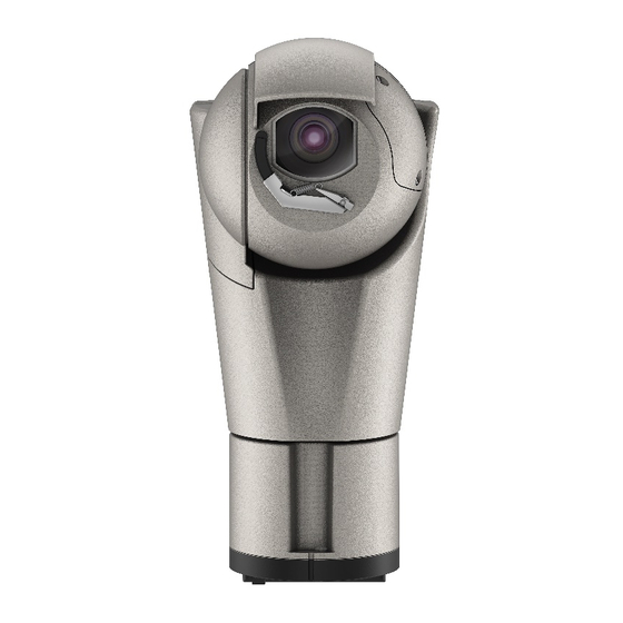
Rugged ptz camera with high performance and extreme reliability
Hide thumbs
Also See for H5A:
- Installation manual (57 pages) ,
- Quick start manual (18 pages) ,
- User manual (56 pages)
Table of Contents
Advertisement
Advertisement
Table of Contents

Related Manuals for Avigilon H5A


Summary of Contents for Avigilon H5A
- Page 1 ENGLISH H5A Rugged PTZ Camera PTZ camera with high performance and extreme reliability English - Instruction manual Italiano - Manuale di istruzioni Français - Manuel d’instructions Deutsch - Bedienungsanleitung Русский - Руководство по эксплуатации...
- Page 3 ENGLISH H5A Rugged PTZ Camera PTZ camera with high performance and extreme reliability English - Instruction manual...
-
Page 5: Table Of Contents
Contents E N G L I S H 1 About this manual ........................5 1.1 Typographical conventions ..............................5 2 Notes on copyright and information on trademarks ............. 5 3 Safety rules..........................5 4 Product description and type designation ................8 4.1 Product overview ................................... - Page 6 11.1 Cleaning the window and plastic parts ........................28 12 Information on disposal and recycling ................29 13 Warranty ..........................29 14 Troubleshooting ........................29 15 Technical data ........................30 15.1 H5A Rugged PTZ camera ..............................30 15.1.1 General ........................................30 15.1.2 Mechanical ......................................30 15.1.3 Electrical .........................................30 15.1.4 Network ........................................30 15.1.5 Illuminators ......................................31...
-
Page 7: About This Manual
CAUTION! The white LED illuminator emits high intensity light. For further details © 2021 Avigilon Corporation. All rights reserved. on configuration and use, refer to the AVIGILON, and the AVIGILON logo are trademarks illuminator accessory manual. - Page 8 • The manufacturer declines all responsibility • Before proceeding with installation, check the for any damage caused by an improper use supplied material to make sure it corresponds of the appliances mentioned in this manual. to the order specification by examining the Furthermore, the manufacturer reserves the right identification labels (4.2 Product marking label, page 8).
- Page 9 • This is a Class A product. In a domestic • Do not use the appliance in the presence of environment this product may cause radio flammable substances. interference. In this case the user may be required • Do not allow children or unauthorised people to to take adequate measures.
-
Page 10: Product Description And Type Designation
4.2 Product marking label type designation Before proceeding further with installation, make sure the material supplied The H5A Rugged PTZ camera is ideal as a video corresponds to the order specification by surveillance solution for outdoor applications in examining the marking labels. -
Page 11: Model Identification
Parapet bracket with internal cable channel for Avigilon H5A Rugged PTZ Camera, grey-white colour (RAL9002) AVUEBP4AA Parapet bracket with quick connectors RJ45 (Ethernet and PoE) + 4 poles for Avigilon H5A Rugged PTZ Camera, grey-white (RAL9002) AVUEBP7AA Parapet bracket with quick connectors RJ45 (Ethernet and PoE) + 7 poles for Avigilon H5A Rugged PTZ... -
Page 12: Preparing The Product For Use
Check the contents to make sure they correspond supplied with the appliance, placing it near with the list of materials as below: the unit so that it can be seen easily. • H5A Rugged PTZ camera • Sunshield • Accessories package: • Allen wrench •... -
Page 13: Installation
6 Installation Never, under any circumstances, make any changes or connections that are not shown in this handbook. Failure to follow the connection instructions that are given in the handbook may create serious safety hazards for people and for the installation. Do not change the wiring in the product as it is supplied to you. -
Page 14: Installation With Internal Cable Passage
6.1.2 Installation with internal cable passage This installation mode allows cable passage inside the mounting brackets. The image below shows the various upright mounting options. AVUEBP0AA AVUEBWAA AVUEBWAA + AVUEAP AVUEBP0AA + AVUEAW AVUEBWAA + AVUEAC AVUEBWAA + AVUEAW Fig. 5 MNGCEVO_2116_EN... -
Page 15: Installation With Internal Cable Passage With Product Inverted
6.1.3 Installation with internal cable passage with product inverted CAUTION! Always secure the product with the safety chain (6.8 Fastening of the safety coupling, page 20). This installation mode allows cable passage inside the mounting brackets. The image below shows the various inverted mounting options. In the event of installation of the product inverted, the sunshield must be assembled as illustrated in the relevant chapter (6.7 Sunshield mounting, page 20) and enable the Ceiling Orientation mode using the web interface. -
Page 16: Installation With Quick Connectors
6.1.4 Installation with quick connectors This installation mode with the quick connectors allows easy and fast replacement of the unit. The image below shows the various upright mounting options. AVUEBP4AA/AVUEBP7AA AVUEBP4AA/AVUEBP7AA + AVUEBWAA AVUEBP4AA/AVUEBP7AA + AVUEBWAA + AVUEAP AVUEBP4AA/AVUEBP7AA + AVUEAW AVUEBP4AA/AVUEBP7AA + AVUEBWAA + AVUEAC AVUEBP4AA/AVUEBP7AA + AVUEBWAA + AVUEAW Fig. -
Page 17: Installation With Quick Connectors With Product Inverted
6.1.5 Installation with quick connectors with product inverted CAUTION! Always secure the product with the safety chain (6.8 Fastening of the safety coupling, page 20). This installation mode with the quick connectors allows easy and fast replacement of the unit. The image below shows the various inverted mounting options. -
Page 18: Typical Connection Of Accessories
6.1.6 Typical connection of accessories The figure displays how the accessories can be connected to the product. CAMERA CAMERA CAMERA CAMERA Network 100m max PHIHONG /POE90U-1BT 100m max PHIHONG AVSURGEPR /POE90U-1BT ETH 100m max 24Vac/24Vdc ETH 100m max or fiber optic AVCOMB100A 24Vac /AVCOMB200A... -
Page 19: Opening The Base Of The Product
6.2 Opening the base of the 6.3 Mounting the bracket product Take special care when attaching and fastening down the apparatus. If the To avoid scratching the product with the hexagonal equipment must be fastened to a concrete wrench, align the groove on the body of the product surface, plugs must be used with a with the screw before screwing it in. -
Page 20: Cable Management
6.4 Cable management The cables must be adequately fastened to the structure to avoid causing the cables to be accidentally unplugged. You must use cables suited to the type of installation you are using. For conductor section and cable sheath diameters which can be used, please refer to the technical data in the relevant chapter (15 Technical data, page 30). -
Page 21: Fixing The Base To The Support
6.5 Fixing the base to the support Insert the memory card into the slot as indicated ( Fig. 16, page 19). Pay attention to the direction of the memory card. For further details on installing the camera with mounts and accessories, refer to the manual provided with the mount or accessory. -
Page 22: Sunshield Mounting
6.7 Sunshield mounting 6.8 Fastening of the safety coupling You can fix the sunshield to the housing using the screws supplied. Take special care when attaching and Pay attention to the fixing. Tightening fastening down the apparatus. If the torque: 1.6Nm (±0.2Nm). equipment must be fastened to a concrete surface, plugs must be used with a minimum traction force of 300dN each. -
Page 23: Connector Board Description
6.9 Connector board description The earth ground cable must always be connected to the relevant terminal (GND_ INT or GND_EXT, Fig. 21, page 21). BOARD DESCRIPTION GND_INT Connector Function Ethernet Power supply Digital I/O S1, S2 Reset to Factory Default Settings GND_INT Earth ground connection, 24Vac/Vdc power GND_EXT... -
Page 24: Connecting The Power Supply
To power the unit, use the power supply units indicated in the technical data sheet of the product on the website: avigilon.com, or use a toroidal Fig. 24 transformer with nominal power of at least 200VA. -
Page 25: Alarm And Relay Connections
6.11 Alarm and relay connections For conductor section and cable sheath diameters which can be used, please refer to the technical data in the relevant chapter (15 Technical data, page 30). Maximum relay voltage and current: consult the technical data in the relevant chapter (15 Technical data, page 30). -
Page 26: Connection Of The Ethernet Cable
6.12 Connection of the Ethernet 6.13 Installation of the upper cable body Use of Ethernet cables with the following Installation of the upper body must take characteristics is highly recommended: place with the base not powered. • Minimum cabling type: Class D (ISO/ Check the LED indicated in the figure is off (Fig. - Page 27 Place the unit body on the base aligning the To avoid scratching the product with the hexagonal reference marks. Be especially careful not to damage wrench, align the groove on the body of the product internal components during installation. with the screw before screwing it in (Fig. 32, page 25). Fig.
-
Page 28: Switching On
0°C (+32°F). The procedure is • Web Interface User Guide — Avigilon High necessary to guarantee correct operation Definition H4 and H5 IP Cameras of the devices even at low temperatures. -
Page 29: Maintenance
The effect of the Factory Default procedure is the same as restoring the factory default settings through When contacting AVIGILON for assistance please the web interface (Hard Reset button). provide the serial number and the identification code To execute the default factory procedure, you need of the model. -
Page 30: Cleaning
11 Cleaning • Assemble the upper body (6.13 Installation of the upper body, page 24). 11.1 Cleaning the window and • Power the unit. Wait for 2 minutes. • Disconnect the power supply to the unit. plastic parts • Open the base of the product (6.2 Opening the base of the product, page 17). -
Page 31: Information On Disposal And Recycling
Reset the equipment by switching off and on again. • Wiper blade. • Slip-ring: maximum 4,000,000 revolutions or operations. • Motor belts: maximum 7,000,000 revolutions or operations. Warranty service and technical support can be obtained by contacting Avigilon Technical Support: avigilon.com/contact-us/. MNGCEVO_2116_EN... -
Page 32: Technical Data
0.14mm² (26AWG). Power consumption with illuminator off: • 20W, PTZ stopped, heating switched off (with 15.1 H5A Rugged PTZ camera the ECO-MODE function enabled, energy saving function that is activated only when the PTZ is 15.1.1 General... -
Page 33: Illuminators
15.1.5 Illuminators 15.1.6 Environment LED illuminator For indoors and outdoors installation Wavelength: 850nm, 940nm (only AVUEIxxx), white Operating temperature light • Continuous functioning: from -40°C (-40°F) up to AVUEIxxx +65°C (149°F) • Wide beam: 40° (horizontal), 16° (vertical) • De-icing function intervention: from -40°C (-40°F) up to -10°C (14°F) •... -
Page 34: Technical Drawings
16 Technical drawings The indicated measurements are expressed in millimetres. Fig. 36 H5A Rugged PTZ Camera. Fig. 37 H5A Rugged PTZ Camera with LED illuminator. MNGCEVO_2116_EN... - Page 35 MNGCEVO_2116_EN...
- Page 36 U.S. & Canada +1 888-281-5182 International +1 604-629-5182 (option 1) support@avigilon.com avigilon.com © 2020, Avigilon Corporation. All rights reserved. AVIGILON and the AVIGILON logo are trademarks of Avigilon Corporation MNGCEVO_2116_EN...
Need help?
Do you have a question about the H5A and is the answer not in the manual?
Questions and answers