
Related Manuals for Avigilon H5SL Series


Summary of Contents for Avigilon H5SL Series
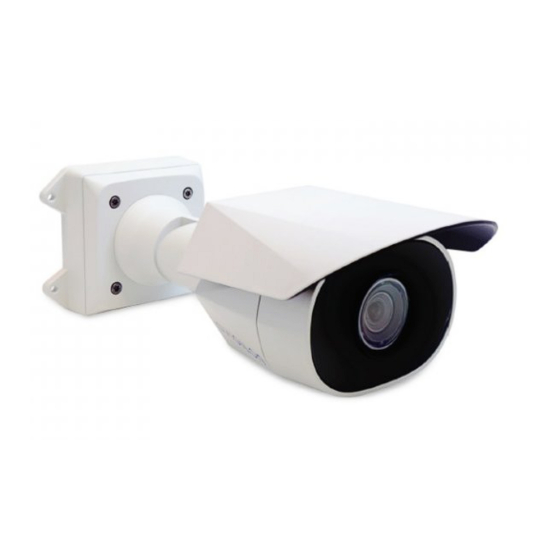
- Page 1 Installation Guide Avigilon H5SL Bullet Camera Models: 1.3C-H5SL-BO1-IR 2.0C-H5SL-BO1-IR 3.0C-H5SL-BO1-IR 3.0C-H5SL-BO2-IR 5.0C-H5SL-BO1-IR 5.0C-H5SL-BO2-IR...
- Page 2 The absence of the symbols ™ and ® in proximity to each trademark in this document or at all is not a disclaimer of ownership of the related trademark. Avigilon Corporation protects its innovations with patents issued in the United States of America and other jurisdictions worldwide (see avigilon.com/patents).
- Page 3 This product is intended to be supplied by Power over Ethernet (PoE) that is a “Limited Power Source” or “LPS”, rated 48 VDC, 9W min. Any external power supply connected to this product may only be connected to another Avigilon product of the same model series. External power connections must be properly insulated.
- Page 4 Avigilon Corporation could void the user’s authority to operate this equipment. To meet the requirements of the EN 50121-4 Railway Applications Standard, use an external power supply or POE injector that is also compliant with EN 50121-4. Please contact Avigilon for assistance regarding supporting equipment.
- Page 5 This symbol means that according to local laws and regulations your product should be disposed of separately from household waste. When this product reaches its end of life, take it to a collection point designated by local authorities. Some collection points accept products for free. The separate collection and recycling of your product at the time of disposal will help conserve natural resources and ensure that it is recycled in a manner that protects human health and the environment.
-
Page 6: Table Of Contents
Table of Contents Overview Mounting Bracket View Rear View Front View Configuration Panel View Side View Installation Camera Package Contents Installation Steps Mounting the Bullet Camera Removing the Configuration Panel Cover Initializing a Camera Username and Password (Optional) Using the USB Wi-Fi Adapter Assigning an IP Address Accessing the Live Video Stream Aiming the Camera... -
Page 7: Overview
Overview Mounting Bracket View 1. Camera mounts Points for installing the camera to the mounting bracket. 2. Mounting hook slots Points to hold the camera to the mounting bracket while connecting the required cables. 3. Mounting holes Holes for securing the mounting bracket to the mounting surface. Overview... -
Page 8: Rear View
Rear View 1. Ethernet port Accepts power and Ethernet connection to the network. The camera can only be powered by Power over Ethernet (PoE). Server communication and image data transmission also occur over this connection. 2. Serial number tag Device information, product serial number and part number label. 3. -
Page 9: Front View
Front View 1. IR illuminator Provides scene illumination in the IR spectrum. 2. Configuration panel cover Covers the configuration panel. Front View... -
Page 10: Configuration Panel View
Card Storage on page 14. 2. Micro USB port Accepts a micro USB to USB adapter. Only required when using the Avigilon USB Wi-Fi Adapter. 3. Link LED indicator Amber LED indicates if there is an active connection in the Ethernet port. -
Page 11: Side View
Side View 1. Sun shroud An adjustable cover to help protect the lens against glare from the sun. 2. Mount arm Adjustable mount arm for positioning the camera. 3. Adjustment screws Provides a locking mechanism for the mount arm. Side View... -
Page 12: Installation
Installation Camera Package Contents Avigilon H5SL Bullet Camera Mounting template sticker 4 screws and anchors for solid walls Installation Steps Complete the following sections to install the device. Mounting the Bullet Camera If the cables for the camera will not be provided from inside the mounting surface, install the junction box first (H4-BO-JBOX). - Page 13 3. Fasten the mounting bracket to the mounting surface or junction box. Note: It is recommended that silicone sealant be applied around the edge of the mounting bracket or junction box to prevent moisture from entering the mounting surface. 4. Insert the mounting hooks on the rear of the camera into the mounting hook slots on the mounting bracket, then let the camera hang.
- Page 14 5. If there are external input or output devices that need to be connected to the camera (for example: door contacts, relays, etc.), connect the devices to the camera's digital I/O connector cables. For more information see Connecting to External Audio and I/O Devices on page 16.
- Page 15 8. Connect the network cable to the camera's Ethernet port. 9. Tuck the extra lengths of cables into the cable entry hole. 10. Raise the camera until it covers the mounting bracket. Mounting the Bullet Camera...
-
Page 16: Removing The Configuration Panel Cover
11. Use the camera mounting screws to fasten the camera to the bracket. Removing the Configuration Panel Cover 1. Use a T20 Pin-In star-shaped driver to unscrew the configuration panel cover. 2. Remove the cover from the configuration panel. Initializing a Camera Username and Password Cameras manufactured after January 1, 2020, do not have a default username or password and will be in a factory default state. -
Page 17: (Optional) Using The Usb Wi-Fi Adapter
For more information, see the Avigilon Cloud Services User Guide. Tip: If you are connecting your Avigilon camera to a 3rd party VMS, you will need to set up the first user through the camera's Web Interface, USB Wifi Adapter, or Camera Configuration Tool before you connect to the 3rd party VMS. -
Page 18: Accessing The Live Video Stream
USB Wi-Fi Adapter on the previous page. Device's web browser interface: http://<camera IP address>/. Network Video Management software application (for example, the Avigilon Control Center™ software). ARP/Ping method. For more information, see Setting the IP Address Using the ARP/Ping Method on page 20. -
Page 19: Aiming The Camera
Cameras manufactured after January 1, 2020: these cameras do not have a default username or password and will be in a factory default state. You must create a user with administrator privileges before the camera is operational. For more information, see Initializing a Camera Username and Password on page 10. -
Page 20: Zooming And Focusing The Camera
Zooming and Focusing the Camera In the camera web browser interface or the Avigilon Control Center software, use the camera’s Image and Display settings to zoom and focus the camera. -
Page 21: Configuring The Camera
For more information, see the Avigilon Camera Configuration Tool User Guide. If the camera is connected to the Avigilon Control Center system, you can use the client software to configure the camera. For more information, see the Avigilon Control Center Client User Guide. -
Page 22: Connecting To External Audio And I/O Devices
Connecting to External Audio and I/O Devices Important: This product is intended to be supplied by Power over Ethernet (PoE). Do NOT connect auxiliary power to the audio or I/O wires or the camera will be damaged. WARNING — This product is intended to be supplied by Power over Ethernet (PoE) that is a “Limited Power Source”... -
Page 23: Connection Status Led Indicator
ACC™ Server. The default connected setting can be changed to Off using the camera's web user interface. For more information see the Avigilon High Definition H4 and H5 IP Camera Web Interface User Guide. Troubleshooting Network Connections and LED Behavior Note: For any of the below LED behaviors, ensure that the camera is getting power and is using a good network cable before trying another solution. - Page 24 LED Behavior Suggested Solution Both LEDs are blinking several Perform a factory reset of the camera using the physical times at the same time, then firmware revert button. Resetting through the camera's web pause and repeat the blinking interface will not produce the desired result. A different LED blinking pattern Perform a factory reset of the camera using the physical than those described above...
-
Page 25: Resetting To Factory Default Settings
Resetting to Factory Default Settings If the device no longer functions as expected, you can choose to reset the device to its factory default settings. Use the firmware revert button to reset the device. The firmware revert button is shown in the following diagram: Figure 1: The firmware revert button in the Configuration Panel. -
Page 26: Setting The Ip Address Using The Arp/Ping Method
For more information, see the Avigilon High Definition H4 and H5 IP Camera Web Interface User Guide. 1. Locate and make note of the MAC Address (MAC) listed on the Serial Number Tag for reference. -
Page 27: Limited Warranty And Technical Support
Limited Warranty and Technical Support Avigilon warranty terms for this product are provided at avigilon.com/warranty. Warranty service and technical support can be obtained by contacting Avigilon Technical Support: avigilon.com/contact. Limited Warranty and Technical Support...
Need help?
Do you have a question about the H5SL Series and is the answer not in the manual?
Questions and answers