Avigilon H5A Installation Manual
Hide thumbs
Also See for H5A:
- Installation manual (57 pages) ,
- Instruction manual (36 pages) ,
- Quick start manual (18 pages)

Related Manuals for Avigilon H5A


Summary of Contents for Avigilon H5A
- Page 1 Installation Guide Avigilon H5A PTZ Camera with IR Models: 2.0C-H5A-IRPTZ-DP40-WP, 4.0C-H5A-IRPTZ-DP36-WP, and 8.0C-H5A-IRPTZ-DP36-WP...
- Page 2 Do not use strong or abrasive detergents when cleaning the device body. Use only accessories recommended by Avigilon. For IR safety, the minimum usage distance shall be 380 mm (15") distance or greater. Risk Group 1. NOTICE: IR emitted from this product. Use appropriate shielding or eye protection.
- Page 3 Consult the dealer or an experienced radio/TV technician for help. Changes or modifications made to this equipment not expressly approved by Avigilon Corporation or parties authorized by Avigilon Corporation could void the user’s authority to operate this equipment. To meet the requirements of the EN 50121-4 Railway Applications Standard, use an external power supply or POE injector that is also compliant with EN 50121-4.
- Page 4 environmental laws and guidelines. Risk of fire, explosion, and burns. Do not disassemble, crush, heat above 100 °C (212 °F), or incinerate. European Union: This symbol means that according to local laws and regulations your product should be disposed of separately from household waste.
- Page 5 © 2023, Avigilon Corporation. All rights reserved. AVIGILON, the AVIGILON logo, AVIGILON CONTROL CENTER, and ACC are trademarks of Avigilon Corporation. ONVIF is a trademark of Onvif, Inc. Other names or logos mentioned herein may be the trademarks of their respective owners. The absence of the symbols ™...
-
Page 6: Table Of Contents
Table of Contents Overview Rear View Front View Top View Pendant Wall Mount View NPT Mount View Installation Package Contents Retrofitting an H4 IR PTZ Installation Steps Installing the Mounting Adapter Installing the Pendant Wall Mount Installing the NPT Mount Connecting Cables Securing the PTZ Camera (Optional) Configuring Onboard Storage... - Page 7 Video Does Not Display After Powering the Camera Limited Warranty and Technical Support...
-
Page 8: Overview
An optional washer can be mounted at this location for cleaning the lens and IR window . Connect digital output 1 from the camera to the washer pump. This will allow the camera WebUI or Avigilon Control Center to activate the washer whenever a washing sequence is initiated. For more information, please refer to the PTZ Camera Web Interface User Guide. -
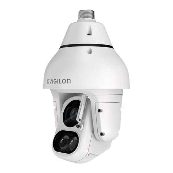
Page 9: Front View
Front View 1. Lens The camera lens is housed behind a protective window. 2. Wiper Wiper rotates 180° to clean both lens and IR window. 3. Variable IR Illuminators High powered infrared LEDs with variable field of view to accommodate different low light situations. The IR illuminators are housed behind a protective window. -
Page 10: Top View
Top View 1. Lanyard anchor The safety lanyard attaches to the anchor to prevent the camera from falling during installation. 2. Ethernet port Accepts an Ethernet connection to a network. Server communication and image data transmission occurs over this connection. Also receives power when it is connected to a network that provides Power over Ethernet. -
Page 11: Pendant Wall Mount View
Pendant Wall Mount View 1. Pendant wall mount Camera mount for walls and other mounting surfaces. 2. Lanyard Connects to the lanyard anchor on the camera base. 3. Tamper resistant screws Star captive screws to fix the dome camera to the mounting adapter. 4. -
Page 12: Npt Mount View
NPT Mount View 1. 1-1/2” NPT-female to NPT-female adapter An adapter for attaching the pendant NPT mount to an NPT pipe. Note: The adapter is not an included accessory supplied by Avigilon and should be sourced separately. 2. Lock nut Locking nut for securing the pendant NPT mount on the NPT-female to NPT-female adapter. -
Page 13: Installation
The Avigilon H5A IR PTZ camera provides easy retrofitting with Avigilon H4 IR PTZ camera installations, with a few exceptions. Keep the following points in mind if you are swapping a new H5A IR PTZ with an installed H4 IR PTZ: Re-use the original mounting location. -
Page 14: Installation Steps
Installation Steps Complete the following sections to install the device. Installing the Mounting Adapter The PTZ camera can only be mounted to a pendant wall mount (IRPTZ-MNT-WALL1) or a pendant NPT mount (IRPTZ-MNT-NPTA1). The mounts are sold separately. Use the pendant wall mount if you will be mounting the camera to a vertical mounting surface such as a wall. Use the pendant NPT mount if you will be mounting the camera to a 1-1/2”... -
Page 15: Installing The Npt Mount
4. Fasten the pendant wall mount to the mounting surface. 5. Tighten the wall mount screws to secure the wall mount to the wall. 6. Connect the safety lanyard from inside the wall mount to the anchor on the PTZ camera. Installing the NPT Mount Note: This procedure requires a 1-1/2”... - Page 16 1. Pull the required cable through the NPT conduit pipe. 2. Apply thread seal tape to the pipe and screw on the 1-1/2” NPT female to NPT female pipe adapter. 3. Screw the lock nut onto the NPT adapter. 4. Apply thread seal tape to the NPT adapter and screw it into the pipe adapter. Make sure the parts are assembled in this order from NPT conduit pipe to camera adapter: a.
-
Page 17: Connecting Cables
5. Connect the safety lanyard from inside the NPT mount to the anchor on the PTZ camera. Connecting Cables Refer to the diagrams in the Overview section for the location of the different connectors. To connect the cables required for proper operation, complete the following: Note: The PTZ camera does not support cables with boots and strain reliefs. - Page 18 1. Make sure the safety lanyard is connected to the camera. 2. Remove the sealing gland caps from the top of the camera. 3. If there are external input or output devices that need to be connected to the camera (for example: door contacts, relays, analog video, speakers, etc.), connect the devices to the camera I/O connector cable.
- Page 19 c. Crimp the connector onto the Ethernet cable. Connecting Cables...
- Page 20 6. Remove the I/O cover and feed the I/O connector cable through the gland cap, cable gland, and I/O cover. The I/O cable gland has a plug in it that must be pulled out before feeding the cable through. 7. Tighten the cable glands around the cables. 8.
-
Page 21: Securing The Ptz Camera
Note: If you need to remove the RJ45 connector from the camera to check a network issue, gently pull the cable towards the locking tab to release the RJ45 plug before pulling upwards. 10. Check that the Connection Status LED indicator indicates the correct state. For more information, see Connection Status LED Indicator on page 23. -
Page 22: (Optional) Configuring Onboard Storage
3. Use the T20 star key to tighten the screws in the mount adapter. Figure 5: Securing the camera to the wall mount adapter. Figure 6: Securing the camera to the NPT adapter. 4. If you are installing the camera to an NPT mount, make sure the mount adapter is secured then tighten the lock nut to fix the camera to its final position. -
Page 23: Initializing A Camera Username And Password
If the camera is in the factory default state you will be redirected to the Add a new user page to create the first user. For more information, see the Avigilon High Definition H4 and H5 IP Camera Web Interface User Guide. -
Page 24: Assigning An Ip Address
For more information, see the Avigilon Cloud Services User Guide. Tip: If you are connecting your Avigilon camera to a 3rd party VMS, you will need to set up the first user through the camera's Web Interface, USB Wifi Adapter, or Camera Configuration Tool before you connect to the 3rd party VMS. - Page 25 These guides are available on help.avigilon.com and on the Avigilon website: avigilon.com/support. For More Information...
-
Page 26: Connecting To Power And External Devices
Connecting to Power and External Devices CAUTION — Be careful to only connect power to the Auxiliary Power Wires or the camera will be damaged. If PoE is not available, the camera may be powered through the auxiliary power cable using either 24 V DC or 24 V AC. -
Page 27: Seamless Failover
4. Yellow (RI_1)— Digital Input, Relay 1. The input voltage must be below 0.7 V to register as a low input. The input voltage should not exceed 5 V when high. 5. Orange (RI_2)— Digital Input, Relay 2 6. Light Green (RI_3)— Unused Wire, do not connect. 7. -
Page 28: Setting The Home Preset Position
(Minutes) field to define the expected amount of idle time before the camera returns to the home position. To use the rule method, you must have an Enterprise Edition or Standard Edition version of the Avigilon Control Center system. To configure the PTZ camera to automatically return to the home position, create a... - Page 29 On the Select Rule Event(s) page, select PTZ idle. On the Select Rule Action(s) page, select Go to Home Preset. Automatically Returning to the Home Position...
-
Page 30: Connection Status Led Indicator
ACC™ Server. The default connected setting can be changed to Off using the camera's web user interface. For more information see the Avigilon High Definition H4 and H5 IP Camera Web Interface User Guide. Troubleshooting Network Connections and LED Behavior Note: For any of the below LED behaviors, ensure that the camera is getting power and is using a good network cable before trying another solution. - Page 31 LED Behavior Suggested Solution Both LEDs are blinking several times at Perform a factory reset of the camera using the physical the same time, then pause and repeat the firmware revert button. Resetting through the camera's web blinking interface will not produce the desired result. A different LED blinking pattern than Perform a factory reset of the camera using the physical those described above...
-
Page 32: Resetting To Factory Default Settings
Resetting to Factory Default Settings If the device no longer functions as expected, you can choose to reset the device to its factory default settings. Use the firmware revert button to reset the device. The firmware revert button is shown in the following diagram: Figure 8: The firmware revert button below the SD card slot. -
Page 33: Setting The Ip Address Using The Arp/Ping Method
For more information, see the Avigilon High Definition H4 and H5 IP Camera Web Interface User Guide. 1. Locate and make note of the MAC Address (MAC) listed on the Serial Number Tag for reference. -
Page 34: Cleaning
From the camera web interface, the washer and wiper can be activated from the Live View page. For more information, see the Avigilon PTZ Camera Web Interface User Guide. From the Avigilon Control Center software, the washer and wiper is activated through the PTZ auxiliary command. For more information, see the software help files. -
Page 35: Troubleshooting
Troubleshooting Video Does Not Display After Powering the Camera Note: The following troubleshooting case only applies to cameras that are powered up in a cold environment of -10°C to -40°C (14°F to -40°F) or lower. To properly power the camera at this lower temperature requires 95 W PoE or auxiliary power supply. - Page 36 Limited Warranty and Technical Support Avigilon warranty terms for this product are provided at avigilon.com/warranty. Warranty service and technical support can be obtained by contacting Avigilon Technical Support: avigilon.com/contact. Limited Warranty and Technical Support...
Need help?
Do you have a question about the H5A and is the answer not in the manual?
Questions and answers