Sign In
Upload
Download
Table of Contents
Contents
Add to my manuals
Delete from my manuals
Share
URL of this page:
HTML Link:
Bookmark this page
Add
Manual will be automatically added to "My Manuals"
Print this page
×
Bookmark added
×
Added to my manuals
Manuals
Brands
Avigilon Manuals
Security Camera
H4SL-D
Installation manual
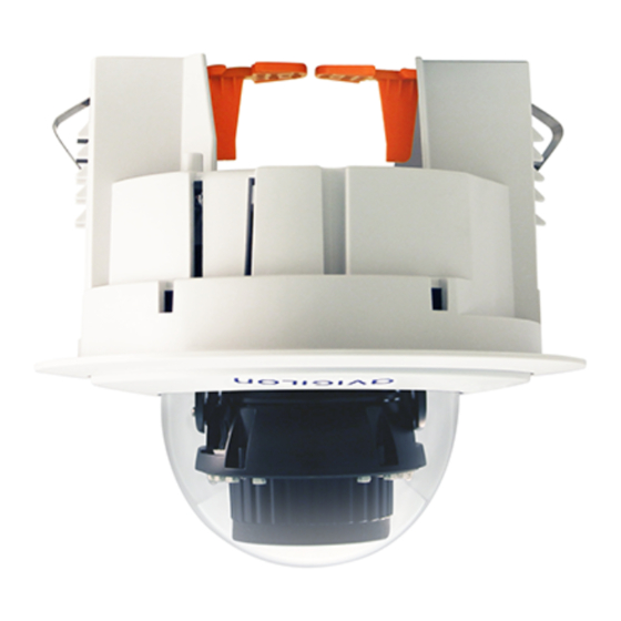
Avigilon H4SL-D Installation Manual
Dome camera models with pendant mount
Hide thumbs
Also See for H4SL-D
:
Installation manual
(30 pages)
,
Installation manual
(28 pages)
1
2
3
4
Table Of Contents
5
6
7
8
9
10
11
12
13
14
15
16
17
18
19
20
21
22
23
24
25
26
27
28
29
30
31
32
33
34
35
36
page
of
36
Go
/
36
Contents
Table of Contents
Troubleshooting
Bookmarks
Table of Contents
Table of Contents
Overview
Cover View
NPT Adapter View
Pendant Wall Mount Bracket View
Pendant Wall Mount View
Camera Base Bottom View
Camera Base Front View
Camera Base Rear View
Installation
Required Tools and Materials
Package Content
Installation Steps
Removing the Dome Cover
Inserting Cables through the Sealing Grommet
Mounting the Dome Camera to a Pipe
(Optional) Mounting the Dome Camera to the pendant Wall Mount
Installing the Camera Base to the Mounting Adapter
(Optional) Using the USB Wi-Fi Adapter
Assigning an IP Address
Accessing the Live Video Stream
Aiming the Dome Camera
(Optional) Configuring Microsd Card Storage
Installing the Dome Cover
Zooming and Focusing the Dome Camera
Configuring the Camera
For more Information
Connection Status LED Indicator
Troubleshooting Network Connections and LED Behavior
Removing the Dome Camera from the Mounting Adapter
Resetting to Factory Default Settings
Setting the IP Address Using the Arp/Ping Method
Specifications
Limited Warranty and Technical Support
Advertisement
Quick Links
Download this manual
Installation Guide
Avigilon H4 SL Dome Camera Models with Pendant Mount
Adapters:
H4SL-D/H4SL-DO plus H4SL-MT-NPTA and CM-MT-WALL
Table of
Contents
Previous
Page
Next
Page
1
2
3
4
5
Advertisement
Table of Contents
Need help?
Do you have a question about the H4SL-D and is the answer not in the manual?
Ask a question
Questions and answers
Related Manuals for Avigilon H4SL-D
Security Camera Avigilon 1.3C-H4SL-D Installation Manual
H4 sl dome camera (30 pages)
Security Camera Avigilon H4SL-MT-DCIL Installation Manual
Avigilon h4 sl dome camera models with in-ceiling mounting adapter (28 pages)
Security Camera Avigilon H4A-G-IR-B Series User Manual
General ip camera web interface (56 pages)
Security Camera Avigilon H6SL Series User Manual
Ip camera web interface (43 pages)
Security Camera Avigilon H4A-DP1 Installation Manual
(36 pages)
Security Camera Avigilon H4A-DO1, H4A-DO1-IR, H4A-DO2, H4A-G-DO1-IR Installation Manual
H4 hd dome camera (35 pages)
Security Camera Avigilon H4A-D1 Installation Manual
H4 hd dome camera (31 pages)
Security Camera Avigilon 1.0C-H4A-B1 Installation Manual
H4 hd ip camera (21 pages)
Security Camera Avigilon H4A-THC-BO Installation Manual
H4 series thermal camera (25 pages)
Security Camera Avigilon H4 Installation Manual
Mini dome camera with pendant mount adapter (26 pages)
Security Camera Avigilon H4 Installation Manual
Fisheye dome camera (46 pages)
Security Camera Avigilon 1.0C-H4IRPTZ-DP45-WP Installation Manual
(36 pages)
Security Camera Avigilon H4A Series Installation Manual
Multisensor dome camera (66 pages)
Security Camera Avigilon H4PRO-B Web Interface User Manual
High definition h.264 ip camera (35 pages)
Security Camera Avigilon H4A B Series User Manual
Ip camera web interface (43 pages)
Security Camera Avigilon H4M-D H3A Series User Manual
Ip camera web interface (43 pages)
This manual is also suitable for:
H4sl-do plus
H4sl
H4sl-mt-npta
Cm-mt-wall
H4sl-do
Table of Contents
Print
Rename the bookmark
Delete bookmark?
Delete from my manuals?
Login
Sign In
OR
Sign in with Facebook
Sign in with Google
Upload manual
Upload from disk
Upload from URL


Need help?
Do you have a question about the H4SL-D and is the answer not in the manual?
Questions and answers