
Related Manuals for Avigilon 3.0C-H5A-CR2-IR


Summary of Contents for Avigilon 3.0C-H5A-CR2-IR
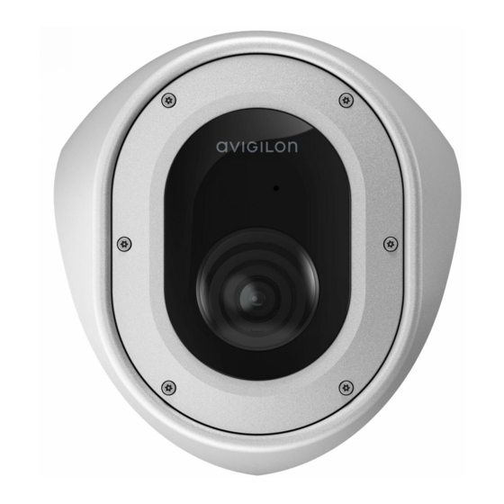
- Page 1 Installation Guide Avigilon H5A Corner Camera Models: 3.0C-H5A-CR2-IR 3.0C-H5A-CR2-IR-SS 5.0C-H5A-CR2-IR 5.0C-H5A-CR2-IR-SS...
- Page 2 The absence of the symbols ™ and ® in proximity to each trademark in this document or at all is not a disclaimer of ownership of the related trademark. Avigilon Corporation protects its innovations with patents issued in the United States of America and other jurisdictions worldwide (see avigilon.com/patents).
- Page 3 (such as from a liquid spill or fallen objects), has been exposed to rain or moisture, does not operate normally, or has been dropped. Do not use strong or abrasive detergents when cleaning the device body. Use only accessories recommended by Avigilon. This device complies with EN 60529 IP66 and IP67 ratings. Regulatory Notices This device complies with part 15 of the FCC Rules.
- Page 4 Consult the dealer or an experienced radio/TV technician for help. Changes or modifications made to this equipment not expressly approved by Avigilon Corporation or parties authorized by Avigilon Corporation could void the user’s authority to operate this equipment. Disposal and Recycling Information When this product has reached the end of its useful life, please dispose of it according to your local environmental laws and guidelines.
-
Page 5: Table Of Contents
Table of Contents Overview Assembled View Housing Front View Gimbal Bottom View Gimbal Front View Housing Rear View Cover - Rear View Conduit Box Accessory View Installation Pre-Deployment In-Box Configuration Required Tools and Materials Camera Package Contents Installation Steps Removing the Front Cover and Gimbal Preparing the Mounting Grommets Mounting and Aiming Video Analytics Cameras Inserting Cables through the Sealing Grommet... - Page 6 Connecting External Power Connecting to External Devices Connection Status LED Indicator Troubleshooting Network Connections and LED Behavior Resetting to Factory Default Settings Setting the IP Address Using the ARP/Ping Method Cleaning Dome Bubble Body For More Information Limited Warranty and Technical Support...
-
Page 7: Overview
Overview Assembled View 1. Front cover Vandal resistant front cover. 2. Recording LED LED turns on when the camera is streaming video to a local microSD card, ACC or another VMS system, or the camera web interface. 3. Microphone Built-in audio receiver. 4. -
Page 8: Housing Front View
Housing Front View 1. Camera lens Lens that captures the video image. 2. LED cable Connect the cable to the LED connector on the front cover to power the Recording LED and IR LED. 3. Microphone cable Connect the cable to the microphone audio connector on the front cover to use the built-in microphone. -
Page 9: Gimbal Bottom View
Gimbal Bottom View 1. Power connector block Accepts a terminal block with either an AC or DC power connection. DC input can be either polarity. Only required when Power over Ethernet is not available. 2. Ethernet port Accepts an Ethernet connection to a network. Server communication and image data transmission occurs over this connection. -
Page 10: Gimbal Front View
Provides connections to external input/output devices. 2. Micro USB port Accepts a micro USB to USB adapter. Only required when using the Avigilon USB Wi-Fi Adapter. 3. microSD card slot Accepts a microSD card for onboard storage. For more information, see... -
Page 11: Housing Rear View
Housing Rear View 1. Cable entry holes (x2) Entry holes for the cables required for camera operation. 2. Mounting holes Mounting points for the camera (x6) with rubber grommets inserted. Housing Rear View... -
Page 12: Cover - Rear View
Cover - Rear View 1. Lanyard Connects to the lanyard anchor on the camera base. 2. Microphone connector Connect the microphone audio cable to use the built-in microphone. 3. LED connector Connect the LED cable to power the camera's Recording LED and IR LED. Cover - Rear View... -
Page 13: Conduit Box Accessory View
Conduit Box Accessory View 1. Rubber gasket Rubber gasket for creating a seal between the corner camera and conduit box accessory. 2. Conduit entry point Removable conduit entry point that can be installed on either side of the conduit box. The conduit box comes with 2 sizes of conduit entry points to use: 3/4"... -
Page 14: Installation
Installation Pre-Deployment In-Box Configuration The camera comes equipped with an RJ45 configuration cable pre-installed for users that want to configure camera settings before installing the camera. The RJ45 connector on the configuration cable is accessible through the small flap on the side of the camera box for easy configuration before unpacking the camera. Note: The maximum recommended duration of in-box configuration is 1 hour. -
Page 15: Camera Package Contents
Cutting tool for cutting cable access hole in the mounting surface Silicone sealant Camera Package Contents Ensure the package contains the following: Avigilon H5A Corner camera RJ-45 grommet piercing cap Microphone audio cable 2 cable entry grommets 6 wall anchors for solid walls, for #8-10 screws 6 mounting screws,#10-1.25"... - Page 16 2. Pull the front cover off of the camera base. 3. Loosen and detach the two screws that secure the gimbal to the base. Removing the Front Cover and Gimbal...
- Page 17 4. Rotate the bottom part of the gimbal upwards after the screws are removed (A), then unhook the gimbal from the slot at the top of the housing and pull the gimbal out (B). Removing the Front Cover and Gimbal...
-
Page 18: Preparing The Mounting Grommets
Overview on page 1 for more information the mounting hole locations. 1. Determine which mounting holes you will use to mount the camera. Tip: Avigilon recommends using all 6 mounting holes to secure your camera, to ensure the Preparing the Mounting Grommets... -
Page 19: Mounting And Aiming Video Analytics Cameras
The camera should be mounted to a stable surface to minimize the physical movement of the camera after installation. For more details, see Designing a Site for Video Analytics. The document is available on the Avigilon website. Inserting Cables through the Sealing Grommet To protect the camera and components from ingress of dust or moisture, you must pull the required cables through the sealing grommet(s) included with the camera for the cable entry holes. -
Page 20: Mounting The Corner Camera Base
1. Pull the tab on the grommet to open a hole for the Ethernet cable. 2. Push an Ethernet cable through the grommet by one of the following methods: a. If the Ethernet cable is uncrimped, push the cable through the grommet. b. - Page 21 Tip: Avigilon recommends using all 6 mounting holes to secure your camera, to ensure the camera is mounted securely and to make the camera ligature-proof. 3. Remove the base from the mounting surface. Drill the 6 mounting holes and one cable entry hole into the mounting surface.
- Page 22 5. Pull the required cables through the cable entry hole. 6. Insert the sealing grommets with the required cables pulled through into the cable entry holes on the back of the camera base. For more information, see Inserting Cables through the Sealing Grommet on page 13.
-
Page 23: Connecting Cables
8. Apply silicone sealant around the edges of the camera base to prevent moisture from entering the mounting surface. Connecting Cables Refer to the diagrams in Overview on page 1 for the location of the different connectors. Connecting Cables... -
Page 24: Mounting The Camera Gimbal To The Base
1. If external input or output devices are part of the installation (for example: door contacts, relays, etc.), connect the devices to the I/O connector block. 2. If the built-in microphone will be used, the factory-intalled audio cable will have to be connected to the inside of the front cover. -
Page 25: Installing The Front Cover
2. Use a phillips screwdriver to tighten the 2 screws and secure the gimbal to the camera base. Installing the Front Cover Note: Before installing the dome cover, we recommend that you first connect to the camera and adjust the aim, zoom, and focus so that the camera covers the required field of view. - Page 26 Assigning an IP Address on page 22 Mounting the Camera Gimbal to the Base on page 18 Configuring the Camera on page 23 Be careful not to touch or scratch the dome bubble. Any marks or fingerprints on the dome bubble will cause unwanted reflections.
-
Page 27: Initializing A Camera Username And Password
For more information, see the Avigilon Cloud Services User Guide. Tip: If you are connecting your Avigilon camera to a 3rd party VMS, you will need to set up the first user through the camera's Web Interface, USB Wifi Adapter, or Camera Configuration Tool before you connect to the 3rd party VMS. -
Page 28: Assigning An Ip Address
CAUTION — Do not force the microSD card into the camera or you may damage the card and the camera. 2. Access the camera’s web interface to enable the onboard storage feature. For more information, see the Avigilon High Definition H4 and H5 IP Camera Web Interface User Guide. Assigning an IP Address... -
Page 29: Focusing The Camera
For more information, see the Camera Configuration Tool User Guide. If the camera is connected to the Avigilon Control Center system, you can use the client software to configure the camera. For more information, see the Avigilon Control Center Client User Guide. -
Page 30: Installation With The Conduit Box Accessory
Installation with the Conduit Box Accessory The conduit gang box is an optional mounting accessory that can be used for installations where the cables are not able to come through the wall and a cable conduit is necessary. Order CNBX-1001 to mount your corner camera with the conduit box. - Page 31 4. Insert the wall anchors into the mounting holes (B). 5. Determine which size conduit pipe you will use for your cables. The conduit box comes with 2 sizes of conduit entry points to use: 3/4" NPT or 1/2" NPT. 6.
-
Page 32: Mounting The Camera Base To The Conduit Box
Mounting the Camera Base to the Conduit Box Perform the following steps to mount the corner camera base to the conduit box. 1. Before mounting the camera base, you will need to prepare it for mounting. Perform these steps first: Removing the Front Cover and Gimbal on page 9 Preparing the Mounting Grommets on page 12. - Page 33 2. Place the base into the mounting location up against the installed conduit box. Use a pen or pencil to mark the spots that will be drilled into the mounting surface for the mounting screws. 3. Remove the base from the mounting surface. Drill the 4 mounting holes into the mounting surface. 4.
- Page 34 5. Pull the required cables through the cable conduit pipe. Use the Ethernet cable clips to keep the cable in place. 6. Insert the sealing grommets with the required cables pulled through into the cable entry holes on the back of the camera base. For more information, see Inserting Cables through the Sealing Grommet on page 13.
- Page 35 8. Check the rubber gasket where the camera and conduit box join. The gasket should fit easily over the top edge of the corner camera. Adjust to correct anywhere the gasket is pinched. 9. Drive the 4 mounting screws to secure the camera in place 10.
-
Page 36: Mounting The Camera Gimbal
entering the mounting surface. Mounting the Camera Gimbal Once the camera base is mounted in place, install the gimbal back into the base: 1. Connect the Ethernet cable and any other cables required. For more information see Connecting Cables on page 17. -
Page 37: Installing The
3. Use a phillips screwdriver to tighten the 2 screws and secure the gimbal to the camera base. Installing the Front Cover Note: Before installing the dome cover, we recommend that you first connect to the camera and adjust the aim, zoom, and focus so that the camera covers the required field of view. - Page 38 Assigning an IP Address on page 22 Mounting the Camera Gimbal to the Base on page 18 Configuring the Camera on page 23 Be careful not to touch or scratch the dome bubble. Any marks or fingerprints on the dome bubble will cause unwanted reflections.
-
Page 39: Cable Connections
Cable Connections Connecting External Power If PoE is not available, the camera needs to be powered through the removable power connector block. Refer to the diagram below for the location of the power connector block. The gimbal will need to be removed from the housing to access the power connector block. - Page 40 1. Ground 2. Input — To activate, connect the Input to the Ground pin. To deactivate, leave disconnected or apply between 3-15 V. 3. Output — When active, Output is internally connected with the Ground pin. Circuit is open when inactive.
-
Page 41: Connection Status Led Indicator
ACC™ Server. The default connected setting can be changed to Off using the camera's web user interface. For more information see the Avigilon High Definition H4 and H5 IP Camera Web Interface User Guide. Troubleshooting Network Connections and LED Behavior Note: For any of the below LED behaviors, ensure that the camera is getting power and is using a good network cable before trying another solution. - Page 42 LED Behavior Suggested Solution Both LEDs are blinking several times at Perform a factory reset of the camera using the physical the same time, then pause and repeat the firmware revert button. Resetting through the camera's web blinking interface will not produce the desired result. A different LED blinking pattern than Perform a factory reset of the camera using the physical those described above...
-
Page 43: Resetting To Factory Default Settings
Resetting to Factory Default Settings If the device no longer functions as expected, you can choose to reset the device to its factory default settings. Use the firmware revert button to reset the device. The firmware revert button is shown in the following diagram: For cameras that have an SD card inserted, resetting the camera will not affect video that has been recorded to the SD card. -
Page 44: Setting The Ip Address Using The Arp/Ping Method
For more information, see the Avigilon High Definition H4 and H5 IP Camera Web Interface User Guide. 1. Locate and make note of the MAC Address (MAC) listed on the Serial Number Tag for reference. -
Page 45: Cleaning
Cleaning Dome Bubble If the video image becomes blurry or smudged in areas, it may be because the dome bubble requires cleaning. To clean the dome bubble: Use hand soap or a non-abrasive detergent to wash off dirt or fingerprints. Use a microfiber cloth or non-abrasive fabric to dry the dome bubble. -
Page 46: For More Information
Additional information about setting up and using the device is available in the following guides: Avigilon Control Center Client User Guide Web Interface User Guide — Avigilon High Definition H4 and H5 IP Cameras Camera Configuration Tool User Guide Designing a Site with Avigilon Video Analytics These guides are available on help.avigilon.com... -
Page 47: Limited Warranty And Technical Support
Limited Warranty and Technical Support Avigilon warranty terms for this product are provided at avigilon.com/warranty. Warranty service and technical support can be obtained by contacting Avigilon Technical Support: avigilon.com/contact. Limited Warranty and Technical Support...
Need help?
Do you have a question about the 3.0C-H5A-CR2-IR and is the answer not in the manual?
Questions and answers