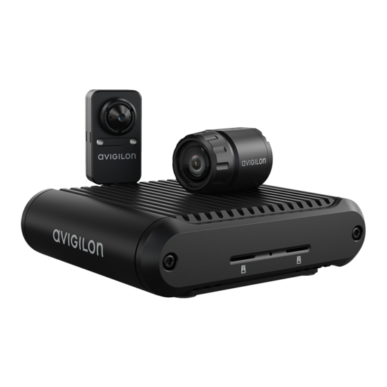
Avigilon H5A Series Installation Manual

Avigilon H5A Series Installation Manual

Modular camera
Hide thumbs Also See for H5A Series:
Table of Contents

Advertisement

Quick Links

Installation Guide
Avigilon™ H5A Modular Camera Models:
3C-H5MOD-MB2
5C-H5MOD-MB2
3C-H5MOD-RP4
H5A-MOD-2P

Advertisement

Table of Contents
loading

Summary of Contents for Avigilon H5A Series

  • Page 1 Installation Guide Avigilon™ H5A Modular Camera Models: 3C-H5MOD-MB2 3C-H5MOD-RP4 5C-H5MOD-MB2 H5A-MOD-2P...
  • Page 2 ©  2022, Avigilon Corporation. All rights reserved. AVIGILON, the AVIGILON logo, AVIGILON CONTROL CENTER, and ACC are trademarks of Avigilon Corporation. ONVIF is a trademark of Onvif, Inc. Other names or logos mentioned herein may be the trademarks of their respective owners. The absence of the symbols ™...
  • Page 3 Do not use strong or abrasive detergents when cleaning the device body. Use only accessories recommended by Avigilon. This product should be installed in restricted access locations. The micro bullet camera imager models 3C-H5MOD-MB2 and 5C-H5MOD-MB2 comply with EN 60529 IP66 rating.
  • Page 4 Changes or modifications made to this equipment not expressly approved by Avigilon Corporation or parties authorized by Avigilon Corporation could void the user’s authority to operate this equipment.
  • Page 5: Table Of Contents

    Table of Contents Overview Main Unit Front View Rear View Bottom View DIN Rail Mount View Micro Bullet Imager Micro Bullet Imager View L-Bracket and Micro Bullet View Right Angle Imager Right Angle Imager View Optional Accessory Flat Bracket View Preparing the Installation Modular Camera System Setup Mounting and Aiming Video Analytics Cameras...
  • Page 6 Mounting Through the Mounting Surface Mounting to a Thin Metal Sheet Right Angle Imager Installation Required Tools and Materials Imager Package Contents Mounting Through the Mounting Surface Installing with Mounting Screws Installing with the Adhesive Strip Mounting the Imager onto a Surface Installing with Mounting Screws Installing with the Adhesive Strip Mounting Through the Mounting Surface with the Bracket...
  • Page 7 Limited Warranty and Technical Support...
  • Page 8: Overview

    Overview Main Unit Front View 1. microSD card slots (x2) Accepts up to two microSD cards for onboard storage. Install microSD cards so the metal contacts are facing towards the mounting feet. For more information, see (Optional) Configuring Onboard Storage page 50.
  • Page 9: Rear View

    HD BNC cable connections for connecting the modular camera main unit to up to two imager modules. 3. Micro USB port Accepts a micro USB to USB adapter. Only required when using the Avigilon USB Wi-Fi Adapter. 4. I/O connector block Provides connections to external input/output and audio devices.
  • Page 10: Bottom View

    Bottom View 1. Mounting feet (x2) Main unit mounting feet that can be used for a tabletop installation or a wall mount. The mounting feet are removed for a DIN rail mounted unit. 2. Mounting feet screws (x4) Screws for fastening the mounting feet to the main unit. 3.
  • Page 11: Micro Bullet Imager

    Micro Bullet Imager Micro Bullet Imager View 1. Camera mount Provides mounting point for the imager. Mount accepts M3 screws. 2. Lens collar Removable lens collar. 3. Camera lens Lens that captures the video image. L-Bracket and Micro Bullet View Micro Bullet Imager...
  • Page 12: Right Angle Imager

    1. L-bracket mounting adapter L-bracket for mounting the micro bullet imager to a flat surface. 2. L-bracket thumbscrew Thumbscrew to adjust the position or angle of the micro bullet imager. 3. L-bracket micro bullet mount Mounting collar for connecting the micro bullet imager to the L-bracket mount. 4.
  • Page 13: Optional Accessory Flat Bracket View

    Optional Accessory Flat Bracket View 1. Lens opening Opening in the bracket for lens to be positioned. 2. Bracket mounting clips (x2) Clips to connect the bracket to the clip retainers on the right angle imager. 3. Mounting slots (x2) Slots for fastening the bracket and right angle imager to a mounting surface with the provided mounting screws.
  • Page 14: Preparing The Installation

    The camera should be mounted to a stable surface to minimize the physical movement of the camera after installation. For more details, see Designing a Site for Video Analytics. The document is available on the Avigilon website. Preparing the Installation...
  • Page 15: Recommended Use Of Hd Bnc Cables

    Recommended Use of HD BNC Cables HD BNC cables are capable of transmitting high resolution video from an imager module to the main unit while also powering the imager module. For optimal performance of the HD BNC cable and to reduce signal degredation, the cable should never be bent or curved any less than a 0.5"...
  • Page 16: Main Unit Installation

    No. 2 Phillips screwdriver — for attaching camera to a mounting surface Main Unit Package Contents Ensure the surface mounted camera package contains the following: Avigilon H5A ,Modular camera main unit Base Mounting Template sticker Power and I/O terminal block 4x screws and anchors —...
  • Page 17: Mounting The Unit To A Wall

    2. Place the unit on a flat surface and connect the required cables. For more information, see Cable Connections on page 22. Mounting the Unit to a Wall Perform the following steps to install the modular camera main unit on a vertical wall. This mounting option is ideal for keeping the unit and it's cables out of the way.
  • Page 18 1. Remove the 4 screws holding the mounting feet in position. 2. Rotate the mounting feet 180° so they match the image below. Connect the mounting feet to the main unit using the 4 screws. Changing the Mounting Feet Position...
  • Page 19: Mounting To A Wall

    Mounting to a Wall 1. Using the Mounting Template, drill 4 pilot holes into the mounting surface for the mounting screws. Discard the mounting template when you are finished. Be aware that the cables will be coming from one of the two ends of the mounting template where the mounting screws are located.
  • Page 20: Mounting The Unit On A Din Rail

    4. Connect the required cables. For more information, see Cable Connections on page 22. Mounting the Unit on a DIN Rail A DIN rail is a standard metal rail that is widely used for mounting equipment, such as on an equipment rack or in a storage room.
  • Page 21 1. Remove the 4 screws holding the mounting feet in position. These parts are not required for a DIN rail mounted main unit. 2. Align the DIN rail mount with the center screw hole and fasten it in place with the screw provided. Mounting the Unit on a DIN Rail...
  • Page 22: Cable Connections

    3. Push the spring portion of the DIN rail mount onto one side of the DIN rail. 4. Rotate the other end of the unit towards the DIN rail until the mount snaps into place. 5. Connect the required cables. For more information, see Cable Connections below.
  • Page 23: Connecting External Power

    4. Power the camera using one of the following methods: Power over Ethernet (PoE) Class 3 — If PoE is available, the LEDs will turn on. PoE, IEEE 802.3af Class 3 is sufficient to power the modular camera main unit and up to two connected imagers. External Power —...
  • Page 24 1. Digital Input — To activate, connect the Input to the Ground pin. To deactivate, leave disconnected or apply between 3-15 V. 2. Ground 3. Digital Output — When active, Output is internally connected with the Ground pin. Circuit is open when inactive.
  • Page 25: Micro Bullet Imager Installation

    No. 2 Phillips screwdriver — for attaching the imager or bracket to a mounting surface Imager Package Contents Ensure the micro bullet imager package contains the following: Avigilon H5A Modular camera micro bullet imager L-shaped mounting bracket and mounting screws 1x double-sided mounting adhesive strip 1x side mounting screw 1x lens securing trimring —...
  • Page 26 To change the position of the micro bullet collar on the L-bracket: 1. Unscrew the thumbscrew holding the collar to the L-bracket. Pull the collar and thumbscrew off of the bracket. 2. Re-insert the thumbscrew into the collar through the hole where you would like it to be mounted. Positioning the Micro Bullet Imager in the L-Bracket...
  • Page 27: Mounting The L-Bracket

    3. Tighten the thumbscrew to hold the collar in place. Mounting the L-Bracket Note: The L-bracket can be mounted in place with either the mounting screws or the mounting adhesive strip. Both options will be described below. Mounting the L-Bracket...
  • Page 28 1. Use one of the following two options to fasten the L-bracket mounting adapter to the mounting surface. Mounting screws: a. Drill two pilot holes into the mounting surface for the mounting screws. Use the mounting slots in the L-bracket as a guide for the holes. b.
  • Page 29 Mounting adhesive strip: a. Peel the protective layer off of each side of the adhesive strip and discard. b. Place the adhesive strip onto the mounting surface, making sure to align it with the . Align the L- bracket with the adhesive strip and press the bracket firmly down onto the adhesive for at least 5 seconds.
  • Page 30: Mounting Through The Mounting Surface

    3. Twist the micro bullet forwards or backwards to change the aim up or down. 4. Tighten the thumbscrew to secure the position of the micro bullet imager. Connect the HD BNC cable. Note: To ensure the micro bullet imager maintains protection from dust and water, make sure to connect the IP66 rated end of the HD BNC cable to the micro bullet.
  • Page 31 1. Unscrew the lens collar from the micro bullet imager. 2. Drill a 25 mm (1.0") hole through the mounting surface. The mounting surface should be no more than 6.35 mm (0.25") thick. A countersink hole may be required if the mounting surface is thicker than 6.35 mm (0.25").
  • Page 32: Mounting To A Thin Metal Sheet

    5. Connect the HD BNC cable. Note: To ensure the micro bullet imager maintains protection from dust and water, make sure to connect the IP66 rated end of the HD BNC cable to the micro bullet. For more information, Recommended Use of HD BNC Cables on page 15.
  • Page 33 1. Drill one pilot hole into the mounting surface for the mounting screw. The pilot hole should be 3.2 mm (1/8") in diameter, for an M3 mounting screw. The mounting surface should be no more than 3 mm (0.12") thick. A countersink hole may be required if the mounting surface is thicker than 3 mm (0.12").
  • Page 34 4. Connect the HD BNC cable. Note: To ensure the micro bullet imager maintains protection from dust and water, make sure to connect the IP66 rated end of the HD BNC cable to the micro bullet. For more information, Recommended Use of HD BNC Cables on page 15.
  • Page 35: Right Angle Imager Installation

    No. 2 Phillips screwdriver — for attaching the imager or bracket to a mounting surface Imager Package Contents Ensure the right angle imager package contains the following: Avigilon H5A Modular camera right angle imager Optional flat bracket — for installations that require additional protection or discretion. 1x double-sided mounting adhesive strip...
  • Page 36 3. Align the lens and mounting holes on the right angle imager with the drilled holes. Secure the imager in place with the mounting screws. 4. Connect the HD BNC cable. Installing with Mounting Screws...
  • Page 37: Installing With The Adhesive Strip

    Installing with the Adhesive Strip 1. Drill a 20 mm (3/4") hole through the mounting surface. If the mounting surface is more than 2 mm (0.08") thick, there may be occlusions on the video image. If a smaller drill hole is preferred, we suggest having a countersink hole in the wall to bring the imager closer to the outer mounting surface.
  • Page 38: Mounting The Imager Onto A Surface

    4. Connect the HD BNC cable. Mounting the Imager onto a Surface For a straightforward mounting installation, you can mount the right angle imager directly to a wall or other mounting surface. Note: The right angle imager can be mounted in place with either the mounting screws or the mounting adhesive strip.
  • Page 39: Installing With Mounting Screws

    Installing with Mounting Screws 1. Drill two pilot holes into the mounting surface for the mounting screws. Use the adhesive strip as a guide for the holes. 2. Align the mounting holes on the right angle imager with the drilled holes. Secure the imager in place with appropriate mounting screws (not supplied).
  • Page 40: Installing With The Adhesive Strip

    Tip: If it suits your installation, you can install the optional flat bracket onto the right angle imager after mounting it to the wall as shown in the image above. Gently push the bracket onto the imager until the bracket mounting clips click into place. Installing with the Adhesive Strip 1.
  • Page 41: Mounting Through The Mounting Surface With The Bracket

    3. Connect the HD BNC cable. Tip: If it suits your installation, you can install the optional flat bracket onto the right angle imager after mounting it to the wall as shown in the image above. Gently push the bracket onto the imager until the bracket mounting clips click into place.
  • Page 42: Installing With Mounting Screws

    mounting adhesive strip. Both options will be described below. Use one of the following two options to install the right angle imager to the mounting surface. Installing with Mounting Screws 1. Drill a 20 mm (3/4") hole through the mounting surface. Use the mounting bracket as a guide for the hole.
  • Page 43 4. Connect the HD BNC cable. Installing with Mounting Screws...
  • Page 44: Installing With The Adhesive Strip

    Installing with the Adhesive Strip 1. Drill a 20 mm (3/4") hole through the mounting surface. If the mounting surface is more than 2 mm (0.08") thick, there may be occlusions on the video image. 2. Peel the protective layer off of each side of the adhesive strip and discard. 3.
  • Page 45: Mounting The Imager And Bracket Onto A Surface

    4. Connect the HD BNC cable. Mounting the Imager and Bracket onto a Surface For a straightforward mounting installation, you can mount the right angle imager and mounting bracket directly to a wall or other mounting surface. Note: The right angle imager can be mounted in place with either the mounting screws or the mounting adhesive strip.
  • Page 46: Installing With Mounting Screws

    Installing with Mounting Screws 1. Drill two pilot holes into the mounting surface for the mounting screws. Use the mounting bracket as a guide for the holes. 2. Align the mounting holes on the mounting bracket with the drilled holes. Secure the bracket in place with the mounting screws.
  • Page 47: Installing With The Adhesive Strip

    3. Connect the HD BNC cable. Installing with the Adhesive Strip 1. Peel the protective layer off of each side of the adhesive strip and discard. 2. Place the adhesive strip onto the mounting surface, making sure to align it with the placement you want the imager to have.
  • Page 48 3. Connect the HD BNC cable. Installing with the Adhesive Strip...
  • Page 49: Connecting To The Camera

    For more information, see the Avigilon Cloud Services User Guide. Tip: If you are connecting your Avigilon camera to a 3rd party VMS, you will need to set up the first user through the camera's Web Interface, USB Wifi Adapter, or Camera Configuration Tool before you connect to the 3rd party VMS.
  • Page 50: Assigning An Ip Address

    169.254.0.0/16 subnet. The IP address settings can be changed using one of the following methods: Device's web browser interface: http://<camera IP address>/. Network Video Management software application (for example, the Avigilon Control Center™ software). ARP/Ping method. For more information, see Setting the IP Address Using the ARP/Ping Method on page 55.
  • Page 51: Configuring The Camera

    For more information, see the Camera Configuration Tool User Guide. If the camera is connected to the Avigilon Control Center system, you can use the client software to configure the camera. For more information, see the Avigilon Control Center Client User Guide.
  • Page 52: Main Unit Led Indicators

    ACC™ Server. The default connected setting can be changed to Off using the camera's web user interface. For more information see the Avigilon High Definition H4 and H5 IP Camera Web Interface User Guide. Troubleshooting Network Connections and LED Behavior Note: For any of the below LED behaviors, ensure that the camera is getting power and is using a good network cable before trying another solution.
  • Page 53: Imager Connection Led Indicators

    LED Behavior Suggested Solution Both LEDs are off and the camera is not Check the General setup page in the camera's web interface to connected or streaming video ensure the LEDs are not disabled. If the LEDs are not disabled, perform a factory reset of the camera using the physical firmware revert button.
  • Page 54: Resetting To Factory Default Settings

    Resetting to Factory Default Settings If the device no longer functions as expected, you can choose to reset the device to its factory default settings. Use the firmware revert button to reset the device. The firmware revert button is shown in the following diagram: 1.
  • Page 55: Setting The Ip Address Using The Arp/Ping Method

    For more information, see the Avigilon High Definition H4 and H5 IP Camera Web Interface User Guide. 1. Locate and make note of the MAC Address (MAC) listed on the Serial Number Tag for reference.
  • Page 56: Cleaning

    Cleaning Micro Bullet Imager Lens Bubble If the video image becomes blurry or smudged in areas, it may be because the lens bubble requires cleaning. Note: Cleaning the micro bullet lens bubble does not apply to right angle imagers as they do not have an accessible lens bubble.
  • Page 57 Limited Warranty and Technical Support Avigilon warranty terms for this product are provided at avigilon.com/warranty. Warranty service and technical support can be obtained by contacting Avigilon Technical Support: avigilon.com/contact. Limited Warranty and Technical Support...

This manual is also suitable for:

3c-h5mod-mb23c-h5mod-rp45c-h5mod-mb2H5a-mod-2p

Table of Contents