Table of Contents
Advertisement
Quick Links
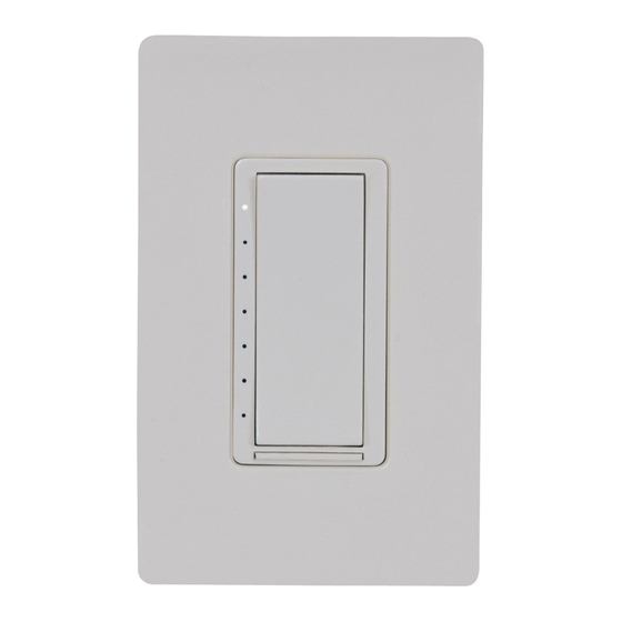
CLW-DIMUEX-P
Cameo® In-Wall Universal Phase Dimmer, 120 VAC
The Crestron®
CLW-DIMUEX-P
dimmer with field replaceable, engravable button caps. The
CLW-DIMUEX-P features auto load detection, which allows the dimmer
to switch between reverse and forward phase dimming depending on the
load connected. infiNET EX® communication technology brings reliability
to the CLW-DIMUEX-P without the need for physical control wiring.
In the Box
1
CLW-DIMUEX-P, Cameo® In-Wall Universal Phase Dimmer,
120 VAC
Additional Items
2
Plastic, Button, 2 Position
4
Plastic, Button, 4 Position
2
Screw, 6-32 x 3/4 in., Truss Head, Combo (2009211)
NOTE:
Refer to the CLW-DIMUEX-P
list of color and texture variations.
Important Notes
WARNINGS:
To avoid fire, shock, or death, turn off power at circuit breaker or
l
fuse and test that power is off before wiring!
is a Cameo® in-wall universal phase
product page
for a complete
New installations should be checked for short circuits prior to
l
installing a CLW-DIMUEX-P dimmer. With power off, close the
circuit and restore power. If the lights do not work or a breaker trips,
check and correct the wiring or fixture (if necessary). Install the
dimmer only when the short is no longer present. The warranty is
void if the dimmer is installed and operated with a shorted load.
CAUTION:
TO REDUCE THE RISK OF OVERHEATING AND POSSIBLE
DAMAGE TO OTHER EQUIPMENT, DO NOT INSTALL TO CONTROL A
RECEPTACLE, A MOTOR-OPERATED APPLIANCE, A FLUORESCENT
LIGHTING FIXTURE, OR A TRANSFORMER-SUPPLIED APPLIANCE.
ATTENTION:
GRADATEURS COMMANDANT UN BALLAST-AFIN DE
RÉDUIRE LE RISQUE DE SURCHAUFFE ET LA POSSIBILITÉ
D'ENDOMMAGEMENT À D'AUTRES MATÉRIELS, NE PAS INSTALLER
POUR COMMANDER UNE PRISE, UN APPAREIL D'ÉCLAIRAGE
FLUORESCENT, UN APPAREIL OPÉRÉ DE MOTEUR OU UN APPAREIL
ALIMENTÉ PAR UN TRANSFORMATEUR.
NOTES:
Codes: This product should be installed and used in accordance with
l
appropriate electrical codes and regulations.
Installation: This product should be installed by a qualified electrician.
l
Wiring: Use copper wire only. For supply connections, use wires rated
l
for at least 75° C (167° F).
Lamp Type: For use with permanently installed LED, incandescent,
l
electronic low voltage, or magnetic low voltage transformer lamp
fixtures only.
Temperature: For use where temperatures are between 32° to 95° F
l
(0° to 35° C).
Electrical Boxes: Devices mount in standard electrical boxes. For easy
l
installation, use 3 1/2 in. (89 mm) deep electrical boxes. Several
devices can be installed in one electrical box (multigang). This requires
derating of the dimming device. For a smooth appearance, one-piece
multigang faceplates (not supplied) can be installed.
Quick Start
1
Advertisement
Table of Contents

Related Manuals for Crestron Cameo CLW-DIMUEX-P


Summary of Contents for Crestron Cameo CLW-DIMUEX-P
- Page 1 Quick Start CLW-DIMUEX-P Cameo® In-Wall Universal Phase Dimmer, 120 VAC The Crestron® CLW-DIMUEX-P is a Cameo® in-wall universal phase New installations should be checked for short circuits prior to dimmer with field replaceable, engravable button caps. The installing a CLW-DIMUEX-P dimmer. With power off, close the CLW-DIMUEX-P features auto load detection, which allows the dimmer circuit and restore power.
-
Page 2: Installation
Low Voltage Applications: Operation of a low voltage circuit with all lamps inoperative or removed may result in current flow in excess of normal levels. To avoid transformer overheating and premature transformer failure, Crestron recommends the following: Do not operate low voltage circuits without operative lamps in place. - Page 3 Quick Start CLW-DIMUEX-P Cameo® In-Wall Universal Phase Dimmer, 120 VAC Multigang Installations In multigang installations, several devices are grouped horizontally in one Changing the Button Assemblies electrical box. For a smooth appearance, one-piece multigang faceplates (not supplied) can be installed. The button assembly can be removed and replaced to accommodate custom button configurations and engravings.
- Page 4 Quick Start CLW-DIMUEX-P Cameo® In-Wall Universal Phase Dimmer, 120 VAC 2. Remove the button from the front of the button assembly. 4. Attach the button assembly to the device. Ensure that the LED strip is on the left side. Power to the load, the buttons, and the LEDs is restored when the button assembly is attached.
-
Page 5: Basic Operation
Operation NOTES: Before using the CLW-DIMUEX-P, ensure the device is using the latest firmware. Check for the latest firmware for the CLW-DIMUEX-P at www.crestron.com/firmware. The device may be warm to the touch during operation. This is normal. Basic Operation The operations described in this guide assume the CLW-DIMUEX-P is operating in Local mode (without the use of a control system). -
Page 6: Disconnecting The Power
Quick Start CLW-DIMUEX-P Cameo® In-Wall Universal Phase Dimmer, 120 VAC Disconnecting the Power Setting Preset Levels Power to the connected loads, the device buttons, and the LEDs can be The CLW-DIMUEX-P can recall and store up to three presets depending disconnected by pushing on the air-gap switch. on the installed button configuration. -
Page 7: Default Button Functions
Quick Start CLW-DIMUEX-P Cameo® In-Wall Universal Phase Dimmer, 120 VAC Default Button Functions The figures below illustrate the default functions available for each physical button configuration and tap or hold actuation sequence. Single Button Press Double Button Press (Press twice within 1/2 second) - Page 8 Quick Start CLW-DIMUEX-P Cameo® In-Wall Universal Phase Dimmer, 120 VAC Single Button Press and Hold (Hold for more than 1/2 second)
-
Page 9: Master And Slave Operation
CLW-SLVU-P slave dimmer. Multipoint dimming is similar to conventional 3- or 4-way switching, allowing dimming control of The device connects to the Crestron network via the infiNET EX a single load from multiple locations in the room. -
Page 10: Troubleshooting
The load will power to 100%. This error code is permanent until the device is power cycled. To check the communications status of the device, tap the top button Disconnect the load and contact Crestron Technical three times and then press and hold it down (tap-tap-tap-press+hold) for Support. - Page 11 50/60 Hz and stable. contact Crestron Technical Support. The following table provides corrective action for possible trouble situations. If further assistance is required, please contact a Crestron customer service representative. Trouble Probable Cause(s)
- Page 12 Service Providers (CSPs) under a limited nonexclusive, nontransferable Software Development Tools License Agreement. Crestron product operating system software is licensed to Crestron dealers, CSPs, and end-users under a separate End-User License Agreement. Both of these Agreements can be found on the Crestron website at www.crestron.com/model/6511056 www.crestron.com/legal/software_license_agreement.
Need help?
Do you have a question about the Cameo CLW-DIMUEX-P and is the answer not in the manual?
Questions and answers