Advertisement
Quick Links
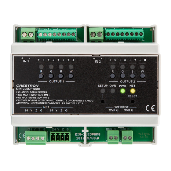
DIN-2LEDPWM8
2 Channel RGBW LED Dimmer, DIN Rail Mount
The Crestron® DIN-2LEDPWM8 is a two channel RGBW dimmer that uses a PWM (pulse width
modulation) frequency for flicker-free performance. A Cresnet® control port is provided for
integration with a Crestron control system.
•
For control of 12–24 VDC LEDs and LED strips
•
Two individually controlled output channels
•
Each output channel provides control of one RGBW LED or four independent LEDs
•
100 W maximum input at 24 VDC
•
60 W maximum input at 12 VDC
•
Cresnet® control port for integration with a Crestron control system and
daisy-chain wiring
•
Override input for test or in case of emergency
Check the Box
Item
DIN-2LEDPWM8
Mounting to a DIN Rail
NOTE:
Observe the following points when installing the DIN-2LEDPWM8.
•
Use the DIN-2LEDPWM8 in an electrical panel with DIN rail mounting provisions.
•
Mount the DIN-2LEDPWM8 in a well-ventilated area.
•
Do not block the venting holes.
Mount the DIN-2LEDPWM8 to the DIN rail (not included):
1.
Hang the DIN-2LEDPWM8 on the top of the DIN rail.
2.
Align the bottom with the DIN rail and snap it into place.
Remove the DIN-2LEDPWM8 from the DIN rail:
1.
Turn off power to the DIN-2LEDPWM8.
2.
Remove all connections from the DIN-2LEDPWM8.
3.
Use a small, flat-head screwdriver to pull the DIN rail release tab down.
4.
Tilt the bottom of the DIN-2LEDPWM8 away from the bottom of the DIN rail and then
remove the DIN-2LEDPWM8.
Wire the DIN-2LEDPWM8
Make LED or LED Strip Connections
The OUTPUT-1 and OUTPUT-2 terminals accept 18–14 AWG wires. The maximum wire length
is 100 ft (30 m).
LED or LED Strip Power Connections
The LED or LED strip receives power from the R +, G +, B +, and/or W + terminal(s). Make power
connections as required for the LED or LED strip. Some LED or LED strips require a power
connection from only one terminal (R +, G +, B +, or W +), other LED or LED strips require a
power connection from each channels (R +, G +, B +, and W +).
NOTE:
Connections to OUTPUT-1 and OUTPUT-2 must remain separate. For example, do not
connect an LED or LED strip to the G + power terminal on OUTPUT-1 and to the G 2 control
terminal on OUTPUT-2.
•
R +: Provides power to the red LED channel.
Qty
•
G +: Provides power to the green LED channel.
1
•
B +: Provides power to the blue LED channel.
•
W +: Provides power to the white LED channel.
LED or LED Strip Control Connections
The LED or LED strip connected to OUTPUT-1 receives control from the R 1, G 2, B 3, and W 4,
and the LED or LED strip connected to OUTPUT-2 receives control from the R 5, G 6, B 7,
and W 8 terminals. Make control connections as required for the LED or LED strip.
•
R 1 and R 5: Red wire to control the red LED channel.
•
G 2 and G 6: Green wire to control the green LED channel.
•
B 3 and B 7: Blue wire to control the blue LED channel.
•
W 4 and W 8: White wire to control the white LED channel.
Wire Two RGBW LEDs or LED Strips
The R 1, G 2, B 3, and W 4 terminals
provide control to the LED or
The R + terminal provides power to the
LED or LED strip.
NOTE:
Do not mix wires between OUTPUT-1 and OUTPUT-2. Connections to OUTPUT-1 and
OUTPUT-2 must remain separate. For example, do not connect an LED or LED strip to
the G + power terminal on OUTPUT-1 and to the G 6 control terminal on OUTPUT-2.
OUTPUT-1:
OUTPUT-2:
The R 5, G 6, B 7, and W 8 terminals
provide control to the LED or
LED strip.
LED strip.
The R + terminal provides power to the
LED or LED strip.
Wire Eight Independent LEDs or LED Strips
OUTPUT-1:
The R 1, G 2, B 3, and W 4 terminals
The R 5, G 6, B 7, and W 8 terminals
provide control to the LED or
provide control to the LED or
LED strip.
The + terminal provides power to the
The + terminal provides power to the
associated LED or LED strip.
associated LED or LED strip.
NOTE:
Do not mix wires between OUTPUT-1 and OUTPUT-2. Connections to OUTPUT-1 and
OUTPUT-2 must remain separate. For example, do not connect an LED or LED strip to
the G + power terminal on OUTPUT-1 and to the G 6 control terminal on OUTPUT-2.
Make Cresnet Connections
The NET (24, Y, Z, G) port provides a connection to the control system and a pass-through
connection to additional Cresnet devices. Make connections as necessary.
CAUTION:
The NET power port must be connected to a Crestron (Model DIN-PWS60,
not supplied) power supply only.
AVERTISSEMENT:
Le port d'alimentation NET doit être connecté uniquement à une source
d'alimentation Crestron (modèle DIN-PWS60, non fournie).
From Contact Closure.
From control
Daisy-chain to
system.
additional Cresnet
devices
OUTPUT-2:
LED strip.
Daisy-chain to override
port on additional
DIN-2LEDPWM8s
Advertisement

Related Manuals for Crestron DIN-2LEDPWM8


Summary of Contents for Crestron DIN-2LEDPWM8
- Page 1 DIN-2LEDPWM8s Use a small, flat-head screwdriver to pull the DIN rail release tab down. From control Daisy-chain to Tilt the bottom of the DIN-2LEDPWM8 away from the bottom of the DIN rail and then system. additional Cresnet remove the DIN-2LEDPWM8.
- Page 2 Toolbox ™ software. Control the R, G, B, and W Channels The R, G, B, and W buttons on the front of the DIN-2LEDPWM8 provide local control of the red (R), green (G), blue (B), and white (W) channels. Toggle the Channels...
Need help?
Do you have a question about the DIN-2LEDPWM8 and is the answer not in the manual?
Questions and answers