
Related Manuals for Crestron DIN-4DIMFLV4


Summary of Contents for Crestron DIN-4DIMFLV4
- Page 1 View this document in HTML crestron.com/docs/9507 Product Manual DIN-4DIMFLV4 4 Channel 0-10V Dimmer, 4 Feeds, DIN Rail Mount Crestron Electronics, Inc.
- Page 2 Crestron Electronics, Inc. in the United States and/or other countries. Other trademarks, registered trademarks, and trade names may be used in this document to refer to either the entities claiming the marks and names or their products. Crestron disclaims any proprietary interest in the marks and names of others. Crestron is not responsible for errors in typography or photography.
-
Page 3: Table Of Contents
Contents Overview Specifications Wiring and Installation Important Instructions Preparing and Connecting Wires Installing the DIN-4DIMFLV4 Connections Important Instructions Operation Net ID Manual Load Control Establish Override Mode Levels Toggle Override Mode Reboot the DIN-4DIMFLV4 Troubleshooting Resources Crestron Support and Training... -
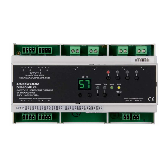
Page 4: Overview
The Crestron® DIN-4DIMFLV4 is a 4-channel lighting control module designed to dim 0-10 V drivers and ballasts. A single model supports both 120 V and 220 V to 240 V applications. The DIN-4DIMFLV4 may also be used for switching of non-dimmable lighting loads up to 5 amps (may not be compatible with some high inrush current loads) and 1/2 HP motors. -
Page 5: Specifications
Height 43.71 in. (95 mm) Width 6.26 in. (159 mm) Depth 2.35 in. (60 mm) Weight 9.2 oz (260 g) Note: 1. May not be compatible with some high inrush current loads. Product Manual — Doc. 9507A DIN-4DIMFLV4 • 2... -
Page 6: Wiring And Installation
A licensed electrician must install the DIN-4DIMFLV4. Before using the DIN-4DIMFLV4, ensure the device is using the latest firmware. Check for the latest firmware for the DIN-4DIMFLV4 at www.crestron.com/firmware. Firmware is loaded onto the device using the Crestron Toolbox™ software or Crestron Home application. -
Page 7: Installing The Din-4Dimflv4
3. Tilt the bottom of the DIN-4DIMFLV4 toward the DIN rail until it snaps into place. To remove the DIN-4DIMFLV4 from the DIN rail, use a small, flat object (e.g., a flat-head screwdriver) to pull the DIN rail release, and tilt the bottom of the DIN-4DIMFLV4 away from the DIN rail. -
Page 8: Connections
8 mm (1/3 in). Tighten terminal blocks to 0.5 - 0.6 N-m (5 in-lbs). Use copper wire only. For high-voltage connections, use wires rated for at least 75°C (167°F). Each channel of the DIN-4DIMFLV4 may be fed from a separate circuit breaker or a single, shared breaker. - Page 9 Product Manual — Doc. 9507A DIN-4DIMFLV4 • 6...
- Page 10 NOTE: Older wiring may be gray for DIM -. 7 • DIN-4DIMFLV4 Product Manual — Doc. 9507A...
-
Page 11: Operation
Operation The DIN-4DIMFLV4 can be controlled via its front panel as well as from a control system. The following local controls are available. Net ID Use the NET ID buttons to change the Net ID of the DIN-4DIMFLV4. Manual Load Control The lighting level of each of the outputs can be manually controlled from the front panel. -
Page 12: Toggle Override Mode
NOTE: If the override lighting levels have not been saved, the factory default override level is 100%. Reboot the DIN-4DIMFLV4 To reboot the DIN-4DIMFLV4, press the RESET button. The outputs are set to the lighting levels currently specied by the control system program. If the control system does not provide any values, the outputs are set to the previously set lighting levels. -
Page 13: Troubleshooting
Troubleshooting The following table provides corrective actions for possible trouble situations. If further assistance is required, please contact a Crestron customer service representative. TROUBLE POSSIBLE CAUSE(S) CORRECTIVE ACTION The device is not receiving power Use a Crestron power source. Verify that the from a Crestron power source. -
Page 14: Resources
Resources The following resources are provided for the DIN-4DIMFLV4. NOTE: You may need to provide your Crestron.com web account credentials when prompted to access some of the following resources. Crestron Support and Training Crestron True Blue Support Crestron Resource Library Crestron Online Help (OLH) Crestron Training Institute (CTI) Portal... - Page 15 Crestron Electronics, Inc. Product Manual — Doc. 9507A 15 Volvo Drive, Rockleigh, NJ 07647 09/11/24 Tel: 888.CRESTRON Specifications subject to Fax: 201.767.7656 change without notice. www.crestron.com...
Need help?
Do you have a question about the DIN-4DIMFLV4 and is the answer not in the manual?
Questions and answers