Crestron DIN-1DIMU4 Operations & Installation Manual
Din rail universal dimmer
Hide thumbs
Also See for DIN-1DIMU4:
- Design manual (84 pages) ,
- Operations & installation manual (36 pages)
Table of Contents
Advertisement
Quick Links
Advertisement
Table of Contents

Related Manuals for Crestron DIN-1DIMU4


Summary of Contents for Crestron DIN-1DIMU4
- Page 1 Crestron DIN-1DIMU4 DIN Rail Universal Dimmer Operations & Installation Guide...
- Page 2 This product is Listed to applicable UL Standards and requirements by Underwriters Laboratories Inc. As of the date of manufacture, the DIN-1DIMU4 has been tested and found to comply with specifications for CE marking and standards per EMC and Radiocommunications Compliance Labelling.
-
Page 3: Table Of Contents
Crestron DIN-1DIMU4 DIN Rail Universal Dimmer Contents DIN Rail Universal Dimmer: DIN-1DIMU4 Introduction ..........................1 Features and Functions ....................1 Applications......................... 3 Specifications ......................4 Physical Description....................6 Setup ............................11 Network Wiring......................11 Identity Code ......................11 Installation ......................... 12 Hardware Hookup ..................... -
Page 5: Din Rail Universal Dimmer: Din-1Dimu4
DIN Rail Universal Dimmer: DIN-1DIMU4 Introduction The DIN-1DIMU4 is a four channel universal lighting control module designed to support dimming of both forward and reverse phase type loads. A single model supports both 120 and 220-240 Volt electronic and magnetic low-voltage, incandescent, neon/cold cathode, 2-wire dimmable fluorescent, and non-dimmable lighting loads up to 5 Amps per channel, 10 Amps total. - Page 6 DIN Rail Installation The DIN-1DIMU4 is designed to snap onto a standard DIN rail for installation in a wall mount enclosure. Wiring connections are made using screw terminals positioned along the bottom, clearly accessible from the front for easy installation and servicing.
-
Page 7: Applications
The DIN-1DIMU4 communicates with a DIN-AP2 2-Series Automation Processor, or other Crestron 2-Series control system, via the Cresnet control network. A pair of Cresnet ports is provided on the DIN-1DIMU4 allowing for easy daisy chaining of several DIN Rail Series automation control modules. -
Page 8: Specifications
DIN Rail Universal Dimmer Crestron DIN-1DIMU4 Specifications Specifications for the DIN-1DIMU4 are listed in the following table. DIN-1DIMU4 Specifications SPECIFICATION DETAILS Load Ratings Dimmer Channels Maximum Per Channel 5 Amps @ 120-240 Volts AC, 50/60 Hz 600 Watts @ 120 Volts AC... - Page 9 60 mm (2.35 in) Weight 912 g (32 oz) 1. The latest software versions can be obtained from the Crestron Web site. Refer to the NOTE following these footnotes. 2. Crestron 2-Series control systems include the AV2 and PRO2. Consult the latest Crestron Product Catalog for a complete list of 2-Series control systems.
-
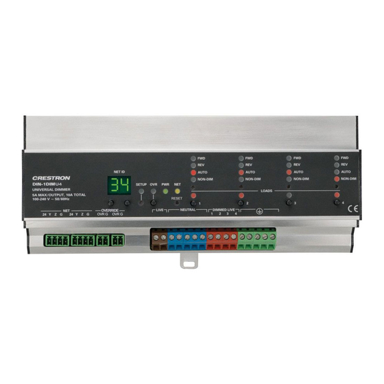
Page 10: Physical Description
This section provides information on the connections, controls and indicators available on your DIN-1DIMU4. DIN-1DIMU4 Physical View DIN-1DIMU4 Overall Dimensions (Front View) 216 mm (8.49 in) 90 mm (3.55 in) 95 mm (3.71 in) 6 • DIN Rail Universal Dimmer: DIN-1DIMU4 Operations & Installation Guide – DOC. 6668D... - Page 11 SETUP (1) Red LED and (1) recessed (LED and Button) miniature push button for enabling setup mode and touch-settable ID (Continued on following page) DIN Rail Universal Dimmer: DIN-1DIMU4 • 7 Operations & Installation Guide – DOC. 6668D...
- Page 12 REV (1 – 4) LED (4) Red LEDs, illuminate when a corresponding channel is operating in a reverse phase mode (Continued on following page) 8 • DIN Rail Universal Dimmer: DIN-1DIMU4 Operations & Installation Guide – DOC. 6668D...
- Page 13 Cresnet slave port Maximum wire size: 1.5 mm (16 AWG) 24: Power (24 Volts DC) Y: Data Z: Data G: Ground (Continued on following page) DIN Rail Universal Dimmer: DIN-1DIMU4 • 9 Operations & Installation Guide – DOC. 6668D...
- Page 14 1. Interface connectors for NET and OVERRIDE ports are provided with the unit. 2. Captive screw terminals accept up to 2.5 mm (12 AWG) wires per terminal. 10 • DIN Rail Universal Dimmer: DIN-1DIMU4 Operations & Installation Guide – DOC. 6668D...
-
Page 15: Setup
For more details, refer to “Check Network Wiring”, which starts on page Identity Code The Net ID of the DIN-1DIMU4 has been factory set to 86. The Net IDs of multiple DIN-1DIMU4 devices in the same system must be unique. -
Page 16: Installation
(32º to 104º F). The relative humidity must be 10% – 90% (non-condensing). NOTE: When installing in an enclosure, high-voltage devices should be grouped separately from low-voltage devices. 12 • DIN Rail Universal Dimmer: DIN-1DIMU4 Operations & Installation Guide – DOC. 6668D... - Page 17 DIN rail release tab while snapping the device onto the DIN rail. 3. Tilt the top of the DIN-1DIMU4 toward the DIN rail until it is secure on the top edge of the rail. Push the DIN rail release upward to lock the DIN-1DIMU4 into place.
-
Page 18: Hardware Hookup
Line Power Input from AC Signal Power Line With the circuit breaker turned off, connect the wires to the terminal blocks per the markings provided on the DIN-1DIMU4. 14 • DIN Rail Universal Dimmer: DIN-1DIMU4 Operations & Installation Guide – DOC. 6668D... - Page 19 NOTE: The DIN-1DIMU4 power feed must be protected by a 10 A (trip curve C) breaker or equivalent. NOTE: The DIN-1DIMU4 outputs must be used for control of permanently installed lighting loads only. Operations & Installation Guide – DOC. 6668D DIN Rail Universal Dimmer: DIN-1DIMU4 • 15...
- Page 20 (building steel). NOTE: To prevent overheating, do not operate this product in an area that exceeds the environmental temperature range listed in the table of specifications. 16 • DIN Rail Universal Dimmer: DIN-1DIMU4 Operations & Installation Guide – DOC. 6668D...
-
Page 21: Programming Software
To have the lighting levels restored to a pre-determined level requires additional programming. At minimum, a five second delay must be added into the program before any commands are sent. Operations & Installation Guide – DOC. 6668D DIN Rail Universal Dimmer: DIN-1DIMU4 • 17... -
Page 22: Programming With Crestron Systembuilder
1. To incorporate the DIN-1DIMU4 into the system, drag the DIN-1DIMU4 from the Lighting | Lighting (Din-Rail Series) folder of the Device Library and drop it into the System Views. 18 • DIN Rail Universal Dimmer: DIN-1DIMU4 Operations & Installation Guide – DOC. 6668D... - Page 23 2. If additional DIN-1DIMU4 devices are to be added, repeat step 1 for each device. Each DIN-1DIMU4 is assigned a different Net ID as it is added. Operations & Installation Guide – DOC. 6668D DIN Rail Universal Dimmer: DIN-1DIMU4 • 19...
-
Page 24: Example Program
Detail View. Each signal in the symbol is described in the SIMPL Windows help file (F1). Example Program An example program for the DIN-1DIMU4 is available from the Crestron Web site (www.crestron.com/exampleprograms). 20 • DIN Rail Universal Dimmer: DIN-1DIMU4 Operations & Installation Guide – DOC. 6668D... -
Page 25: Uploading And Upgrading
DIN-1DIMU4. 3. Display the DIN-1DIMU4’s “System Info” window (click the icon); communications are confirmed when the device information is displayed. Operations & Installation Guide – DOC. 6668D DIN Rail Universal Dimmer: DIN-1DIMU4 • 21... -
Page 26: Programs And Firmware
Network Device Tree) to show all network devices connected to the control system. Right-click on the DIN-1DIMU4 to display actions that can be performed on the DIN-1DIMU4. 22 • DIN Rail Universal Dimmer: DIN-1DIMU4 Operations & Installation Guide – DOC. 6668D... -
Page 27: Operation
DIN Rail Universal Dimmer Operation NET ID Use the NET ID buttons to change the Net ID of the DIN-1DIMU4. For information on Net ID, refer to “Identity Code” which starts on page 11. Manual The lighting level of each output can be manually controlled from the Control front panel. - Page 28 Similarly, if the program defines a channel as dimmable, it cannot be set to non-dim locally. When assigned as dimmable in the program, the auto load type is selected by default. 24 • DIN Rail Universal Dimmer: DIN-1DIMU4 Operations & Installation Guide – DOC. 6668D...
- Page 29 The NON-DIM LED will illuminate when AUTO operating as a switch. NON-DIM Operating mode should be set to NON-DIM when controlling non-dimmable fixtures. Operations & Installation Guide – DOC. 6668D DIN Rail Universal Dimmer: DIN-1DIMU4 • 25...
-
Page 30: Problem Solving
PWR LED DIN-1DIMU4 is Ensure circuit breaker blinks. not receiving is not tripped. power from the AC line. (Continued on following page) 26 • DIN Rail Universal Dimmer: DIN-1DIMU4 Operations & Installation Guide – DOC. 6668D... - Page 31 Add a minimum 10W blinking fast. dimming. incandescent lamp in Light connected parallel with to dimmer transformers. intermittently flashes to full brightness. (Continued on following page) Operations & Installation Guide – DOC. 6668D DIN Rail Universal Dimmer: DIN-1DIMU4 • 27...
-
Page 32: Check Network Wiring
The wire gauge and the Cresnet power usage of the run should be used in the following equation to calculate the cable length value on the equation’s left side. 28 • DIN Rail Universal Dimmer: DIN-1DIMU4 Operations & Installation Guide – DOC. 6668D... - Page 33 Use of a Cresnet Hub/Repeater (DIN-HUB) is advised whenever the number of Cresnet devices on a network exceeds 20 or when the combined total length of Cresnet cable exceeds 914 meters (3000 feet). Operations & Installation Guide – DOC. 6668D DIN Rail Universal Dimmer: DIN-1DIMU4 • 29...
-
Page 34: Reference Documents
Check the Crestron Web site periodically for manual update availability and its relevance. Updates are identified as an “Addendum” in the Download column. 30 • DIN Rail Universal Dimmer: DIN-1DIMU4 Operations & Installation Guide – DOC. 6668D... -
Page 35: Return And Warranty Policies
Purchasers should inquire of the dealer regarding the nature and extent of the dealer's warranty, if any. CRESTRON shall not be liable to honor the terms of this warranty if the product has been used in any application other than that for which it was intended or if it has been subjected to misuse, accidental damage, modification or improper installation procedures. - Page 36 Crestron Electronics, Inc. Operations & Installation Guide – DOC. 6668D 15 Volvo Drive Rockleigh, NJ 07647 (2020750) Tel: 888.CRESTRON 11.10 Fax: 201.767.7576 Specifications subject to www.crestron.com change without notice.
Need help?
Do you have a question about the DIN-1DIMU4 and is the answer not in the manual?
Questions and answers