
Related Manuals for Kichler Lighting Grace 300316


Summary of Contents for Kichler Lighting Grace 300316
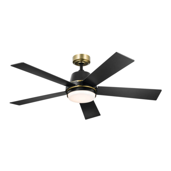
- Page 1 52" Grace LED Product images may vary slightly from actual product. INSTRUCTION MANUAL...
-
Page 2: Table Of Contents
TABLE OF CONTENTS SAFETY RULES …………………………………………………………………………..3 ATTACHING THE FAN BLADES …………………………......11 TOOLS REQUIRED …………………………..………………………………..………...4 INSTALLING THE SWITCH HOUSING …………………………....12 PACKAGE CONTENTS ………………............4 INSTALLING THE LIGHT KIT AND ACRYLIC SHADE………..13 MOUNTING OPTIONS …………..............5 OPERATING INSTRUCTIONS …………………………...…………..14 HANGING THE FAN ………………………………………………………………..6 TROUBLESHOOTING …………………………....………………………16 ELECTRICAL CONNECTIONS…………..........9 FCC INFORMATION..………………………………………………………...17 FINISHING THE MOTOR INSTALLATION........10... -
Page 3: Safety Rules
SAFETY RULES READ AND SAVE THESE INSTRUCTIONS CAUTION CAUTION – RISK OF SHOCK – Disconnect Power at – RISK OF SHOCK – Disconnect Power at Make sure the installation site you choose allows a minimum clearance of 7 feet from the blades to the floor the main circuit breaker panel or main fuse box before the main circuit breaker panel or main fuse box before and at least 30 inches from the ends of the blades to any... -
Page 4: Tools Required
TOOLS REQUIRED Phillips screwdriver Blade screwdriver 11 mm wrench Step ladder Wire cutters PACKAGE CONTENTS Unpack your fan and check the contents . You should have the following items: A. Mounting bracket K .Remote Control Kit: B. Ball / downrod assembly Remote Control (1) C. -
Page 5: Mounting Options
MOUNTING OPTIONS If there isn’t an existing UL (cUL for Canadian Installation ) listed mounting box, then read the following instructions. Disconnect the power by removing fuses or turning off circuit breakers. Secure the outlet box directly to the building structure. Use Outlet box appropriate fasteners and building materials. -
Page 6: Hanging The Fan
HANGING THE FAN Outlet Box REMEMBER REMEMBER to turn off the power before you begin installation. This is Washer necessary for your safety and also the proper programming of the control system. To properly install your ceiling fan, follow the steps below. Screw Step 1. - Page 7 HANGING THE FAN Clevis Pin Step 3. Step 3. Remove the hairpin and clevis pin from the downrod assembly, retain for later use.(Fig.8) Hair pin Fig. 8 Set Screw Step 4. Step 4. Loosen the two set screws on the motor coupling.(Fig. 9) Fig.
- Page 8 HANGING THE FAN Step 6. Step 6. Pass the clevis pin through the downrod and coupling found on the Hairpin Clevis Pin motor assembly, and secure with the hair pin. Tighten set screws found on Set Screw the coupling. (Fig. 11 ) Coupling Fig.
-
Page 9: Electrical Connections
MAKE THE ELECTRICAL CONNECTIONS Mounting Bracket Receiver WARNING: WARNING: To avoid possible electrical shock, be sure you have turned off To avoid possible electrical shock, be sure you have turned off the power at the main circuit panel before wiring. Follow the steps below the power at the main circuit panel before wiring. -
Page 10: Finishing The Motor Installation
MAKE THE ELECTRICAL CONNECTIONS Mounting Bracket Step 4. Step 4. If your outlet box has a ground wire ( green or bare copper ) connect If your outlet box has a ground wire ( green or bare copper ) connect it to the fan ground wires : otherwise connect the fan ground wire to the it to the fan ground wires : otherwise connect the fan ground wire to the mounting bracket. -
Page 11: Attaching The Fan Blades
FINISHING THE MOTOR INSTALLATION Step 3. Step 3. Securely attach and tighten the canopy hole cover over the shoulder Securely attach and tighten the canopy hole cover over the shoulder screws in the mounting bracket utilizing the keyslot twist-lock feature. (Fig.17) screws in the mounting bracket utilizing the keyslot twist-lock feature. -
Page 12: Installing The Switch Housing
INSTALLING THE SWITCH HOUSING Step 1. Step 1. Remove one of three screws which preinstalled on mounting plate and Remove one of three screws which preinstalled on mounting plate and keep for later use. Loosen the other two (do not remove). (Fig. 19) keep for later use. -
Page 13: Installing The Light Kit And Acrylic Shade
INSTALLING THE LIGHT KIT AND ACRYLIC SHADE NOTE: NOTE: Before continuing installation, confirm that the power is still turned off Before continuing installation, confirm that the power is still turned off at the main circuit breaker or by removing the circuit fuse. Turning the power at the main circuit breaker or by removing the circuit fuse. -
Page 14: Operating Instructions
OPERATING INSTRUCTIONS Restore electrical power to the outlet box by turning the electricity on the Restore electrical power to the outlet box by turning the electricity on the main fuse box. main fuse box. Step 1. Step 1. Select a location to install your handset control holder, install the Select a location to install your handset control holder, install the holder as shown. - Page 15 OPERATING INSTRUCTIONS For DIMMER function: press and hold For DIMMER function: press and hold button to dim the light. The light will button to dim the light. The light will cycle from bright to dim to bright until button is released. Light will maintain cycle from bright to dim to bright until button is released.
-
Page 16: Troubleshooting
TROUBLESHOOTING Problem Problem Solution Solution Fan will not start. Fan will not start. 1. Check circuit fuses or breakers. 1. Check circuit fuses or breakers. 2. Check all electrical connections to ensure proper contact. 2. Check all electrical connections to ensure proper contact. CAUTION: CAUTION: Make sure the main power is OFF when checking Make sure the main power is OFF when checking any electrical connection. -
Page 17: Fcc Information
FCC Information This device complies with part 15 of the FCC Rules. Operation is subject to the following two conditions: 1.)This device may not cause harmful interference, and 2.)This device must accept any interference received, including interference that may cause undesired operation. Note: Note: This equipment has been tested and found to comply with the limits for a Class B digital device, pursuant to part 15 of the FCC Rules. - Page 18 KICHLER LIGHTING 7711 EAST PLEASANT VALLEY ROAD CLEVELAND, OHIO 44131-8010 CUSTOMER SERVICE 866.558.5706 8:00 AM TO 5:00 PM EST, MONDAY - FRIDAY © Kichler Lighting LLC. All Rights Reserved.
- Page 19 52" Grace LED Les images du produit pourraient légèrement varier par rapport au produit réel. MANUEL D’INSTRUCTION...
- Page 20 TABLE DES MATIÈRES RÈGLES DE SÉCURITÉ................3 FIXATION DES PALES DU VENTILATEUR........11 OUTILS NÉCESSAIRES................4 INSTALLATION DU KIT D'ÉCLAIRAGE ET DU VERRE....12 CONTENU DE L'EMBALLAGE..............4 INSTALLATION DU KIT D’ECLAIRAGE ET DE L ’ OMBRE OPTIONS DE MONTAGE................5 ACRYLIQUE ....................13 ACCROCHAGE DU VENTILATEUR.............6 INSTRUCTIONS D'UTILISATION............14 CONNEXIONS ÉLECTRIQUES..............9 DÉPANNAGE....................16...
-
Page 21: Règles De Sécurité
RÈGLES DE SÉCURITÉ LIRE ET CONSERVER CES INSTRUCTIONS AT T E N T I O N AT T E N T I O N - R I S Q U E D E C H O C - D é b r a n c h e z - R I S Q U E D E C H O C - D é... -
Page 22: Contenu De L'emballage
OUTILS REQUIS Tournevis Phillips Tournevis à pale Clé de 11 mm Échelle graduée Coupe-fil CONTENU DE L'EMBALLAGE Déballez votre ventilateur et vérifiez son contenu. Vous devriez avoir les éléments suivants : A. Bloc-moteur K. Kit de télécommande: B. Pale de ventilateur Télécommande (1) C. -
Page 23: Options De Montage
OPTIONS DE MONTAGE S'il n'existe pas de boîte de montage homologuée UL (cUL pour installation canadienne), lisez les instructions suivantes. Débranchez l'alimentation en retirant les fusibles ou en coupant les disjoncteurs. Fixez la boîte de sortie directement sur la structure du bâtiment. Boîte de sortie Utilisez des fixations et des matériaux de construction appropriés. -
Page 24: Accrochage Du Ventilateur
ACCROCHAGE DU VENTILATEUR Boîtier de sortie N'oubliez pas N'oubliez pas de couper le courant avant de commencer l'installation. Ceci de couper le courant avant de commencer l'installation. Ceci Rondelle est nécessaire pour votre sécurité et aussi pour la bonne programmation est nécessaire pour votre sécurité... - Page 25 ACCROCHAGE DU VENTILATEUR Chape Étape 3. Étape 3. Retirez la goupille et la chape de l'ensemble de la tige descendante, Retirez la goupille et la chape de l'ensemble de la tige descendante, conservez-les pour une utilisation ultérieure(Fig. 8). conservez-les pour une utilisation ultérieure(Fig. 8). Goupille Fig.
- Page 26 ACCROCHAGE DU VENTILATEUR Étape 6. Étape 6. Faites passer l'axe de chape à travers la tige de descente et Faites passer l'axe de chape à travers la tige de descente et Goupille Chape l'accouplement qui se trouvent sur le moteur, et fixez-le avec la goupille. l'accouplement qui se trouvent sur le moteur, et fixez-le avec la goupille.
-
Page 27: Connexions Électriques
EFFECTUER LES CONNEXIONS ÉLECTRIQUES Bloc-moteur Récepteur AVERTISSEMENT : AVERTISSEMENT : Pour éviter tout risque de choc électrique, assurez-vous Pour éviter tout risque de choc électrique, assurez-vous d'avoir coupé le courant au panneau de circuit principal avant de procéder d'avoir coupé le courant au panneau de circuit principal avant de procéder au câblage. -
Page 28: Terminer L'installation Du Moteur
EFFECTUER LES CONNEXIONS ÉLECTRIQUES Support de montage Étape 4. Étape 4. Si votre boîtier de prise de courant est équipé d'un fil de terre (vert Si votre boîtier de prise de courant est équipé d'un fil de terre (vert ou cuivre nu), connectez le aux fils de terre du ventilateur. Sinon, connectez ou cuivre nu), connectez le aux fils de terre du ventilateur. -
Page 29: Fixation Des Pales Du Ventilateur
TERMINER L'INSTALLATION DU MOTEUR Étape 3. Étape 3. Fixez et serrez fermement le couvercle du trou de l'auvent sur les vis Fixez et serrez fermement le couvercle du trou de l'auvent sur les vis à épaulement du support de montage en utilisant le dispositif de verrouillage à... - Page 30 INSTALLATION DU BOÎTIER DE L'INTERRUPTEUR Étape 1 : Étape 1 : Retirez l'une des trois vis préinstallées sur la plaque de montage et Retirez l'une des trois vis préinstallées sur la plaque de montage et conservez-la pour une utilisation ultérieure. Desserrez les deux autres [ne les conservez-la pour une utilisation ultérieure.
-
Page 31: Installation Du Kit D'éclairage Et Du Verre
INSTALLATION DU KIT D'ÉCLAIRAGE ET DU VERRE REMARQUE : REMARQUE : Avant de poursuivre l'installation, vérifiez que l'alimentation est Avant de poursuivre l'installation, vérifiez que l'alimentation est toujours coupée au niveau du disjoncteur principal ou en retirant le fusible du toujours coupée au niveau du disjoncteur principal ou en retirant le fusible du circuit. -
Page 32: Instructions D'utilisation
INSTRUCTIONS D'UTILISATION Rétablissez l'alimentation électrique de la boîte de prise en mettant le courant Rétablissez l'alimentation électrique de la boîte de prise en mettant le courant sur la boîte à fusibles principale. sur la boîte à fusibles principale. Étape 1. Étape 1. - Page 33 INSTRUCTIONS D'UTILISATION Pour la fonction de gradateur d’éclairage : appuyez sur le bouton Pour la fonction de gradateur d’éclairage : appuyez sur le bouton maintenez-le enfoncé pour le gradateur de la lumière. La lumière changera maintenez-le enfoncé pour le gradateur de la lumière. La lumière changera graduellement en descendant jusqu'à...
-
Page 34: Dépannage
DÉPANNAGE Problème Problème Solution Solution 1.Vérifiez les fusibles ou les disjoncteurs. 1.Vérifiez les fusibles ou les disjoncteurs. 2.Vérifiez toutes les connexions électriques pour assurer un contact correct. 2.Vérifiez toutes les connexions électriques pour assurer un contact correct. ATTENTION : ATTENTION : Assurez-vous que l'alimentation Assurez-vous que l'alimentation principale est coupée lorsque vous vérifiez une connexion électrique. -
Page 35: Informations Ccf
INFORMATIONS CCF Cet appareil est conforme à la partie 15 des règles de la FCC. Son fonctionnement est soumis aux deux conditions suivantes : 1.)Cet appareil ne doit pas causer d’interférences nuisibles, et 2.)Cet appareil doit accepter toute interférence reçue, y compris les interférences qui peuvent provoquer un fonctionnement indésirable. - Page 36 KICHLER LIGHTING 7711 EAST PLEASANT VALLEY ROAD CLEVELAND, OHIO 44131 SERVICE À LA CLIENTÈLE 866.558.5706 8 h à 17 h EST, DU LUNDI AU VENDREDI © Kichler Lighting LLC. Tous droits réservés.
- Page 37 52" Grace LED Las imágenes pueden presentar diferencias con respecto al producto recibido. MANUAL DE INSTRUCCIONES...
- Page 38 ÍNDICE NORMAS DE SEGURIDAD..............3 COLOCACION LAS ASPAS DEL VENTILADOR......11 HERRAMIENTAS NECESARIAS............4 INSTALACIÓN DE LA CAJA DEL INTERRUPTOR......12 CONTENIDO DEL EMBALAJE..............4 INSTALACIÓN DEL KIT DE LUZ Y DEL DOSEL ACRÍLICO..13 OPCIONES DE MONTAJE...............5 INSTRUCCIONES DE MANEJO............14 INSTALACIÓN DEL VENTILADOR............6 SOLUCIÓN DE PROBLEMAS...............18 CONEXIONES ELÉCTRICAS..............9 INFORMACIÓN SOBRE FCC..............19 TERMINANDO LA INSTALACIÓN DEL MOTOR......10...
-
Page 39: Normas De Seguridad
NORMAS DE SEGURIDAD LEA Y GUARDE ESTAS INSTRUCCIONES PRECAUCIÓN - RIESGO DE DESCARGA ELÉCTRICA - PRECAUCIÓN - RIESGO DE DESCARGA ELÉCTRICA - Asegúrese de que el lugar de instalación que elija permita Desconecte la corriente en el panel del Desconecte la corriente en el panel del un espacio mínimo de 7 pies (2 metros) entre las aspas y el interruptorprincipal o en la caja de fusibles principal antes interruptorprincipal o en la caja de fusibles principal antes... -
Page 40: Herramientas Necesarias
HERRAMIENTAS NECESARIAS Destornillador Phillips Destornillador plano Llave de 11 mm. Escaleras de tijera (de mano). Cortador de cables. CONTENIDO DEL EMBALAJE Desempaque su ventilador y revise el contenido. Los siguientes componentes deberían encontrarse en el embalaje: A. Soporte de montaje K. -
Page 41: Opciones De Montaje
OPCIONES DE MONTAJE Si no existe una caja de montaje listada por UL (CUL para la instalación Canadiense), entonces lea las instrucciones siguientes. Desconecte la corriente quitando los fusibles o apagando los interruptores generales. Caja de Sujete la caja de distribución directamente a la estructura del distribución edificio. -
Page 42: Instalación Del Ventilador
INSTALACIÓN DEL VENTILADOR (SUSPENSIÓN) Caja de distribución RECUERDE RECUERDE desconectar/apagar la corriente antes de empezar con la desconectar/apagar la corriente antes de empezar con la Arandela instalación y el cableado. Esto es necesario para su seguridad y también para instalación y el cableado. Esto es necesario para su seguridad y también para la correcta programación del sistema de control. - Page 43 INSTALACIÓN DEL VENTILADOR (SUSPENSIÓN) Perno de horquilla Paso 3. Paso 3. Quite el pasador y el perno de la horquilla del montaje de la tija, y Quite el pasador y el perno de la horquilla del montaje de la tija, y Pasador de consérvelos para su uso posterior.(Img.
- Page 44 INSTALACIÓN DEL VENTILADOR (SUSPENSIÓN) Pasador de Paso 6. Paso 6. Pase el perno de horquilla a través de la tija y el acoplamiento que Pase el perno de horquilla a través de la tija y el acoplamiento que horquilla (tipo R) Perno de horquilla se encuentra en el montaje del motor, y asegúrelo con el pasador (tipo...
-
Page 45: Conexiones Eléctricas
CONEXIONES ELÉCTRICAS Soporte de montaje Recibidor ADVERTENCIA: ADVERTENCIA: Para evitar posibles descargas eléctricas, asegúrese Para evitar posibles descargas eléctricas, asegúrese de cortar la corriente en el panel del circuito principal antes de realizar el de cortar la corriente en el panel del circuito principal antes de realizar el cableado. -
Page 46: Terminando La Instalación Del Motor
CONEXIONES ELÉCTRICAS Soporte del montaje Paso 4. Paso 4. Si su caja de distribución tiene un cable de tierra (verde o cobre Si su caja de distribución tiene un cable de tierra (verde o cobre desnudo) conéctelo a los cables de tierra del ventilador; de lo contrario, desnudo) conéctelo a los cables de tierra del ventilador;... -
Page 47: Colocacion Las Aspas Del Ventilador
TERMINANDO LA INSTALACIÓN DEL MOTOR Paso 3. Paso 3. Fije y apriete firmemente el tapagujeros de la cubierta del florón Fije y apriete firmemente el tapagujeros de la cubierta del florón superior sobre los tornillos de resalto en el soporte de montaje, girando para superior sobre los tornillos de resalto en el soporte de montaje, girando para bloquear el conjunto en la ranura bocallave. -
Page 48: Instalación De La Caja Del Interruptor
INSTALACIÓN DE LA CAJA DEL INTERRUPTOR Paso 1. Paso 1. Quite uno de los tornillos puesto en la placa de montaje y guárdelo Quite uno de los tornillos puesto en la placa de montaje y guárdelo para más tarde. Afloje los otros dos (no los quite). (Img. 19) para más tarde. -
Page 49: Instalación Del Kit De Luz Y Del Dosel Acrílico
INSTALACIÓN DEL KIT DE LUZ Y DEL DOSEL ACRÍLICO NOTA: NOTA: Antes de continuar con la instalación, asegúrese de que la corriente Antes de continuar con la instalación, asegúrese de que la corriente sigue apagada en el interruptor general o quitando el fusible del circuito. sigue apagada en el interruptor general o quitando el fusible del circuito. -
Page 50: Instrucciones De Manejo
INSTRUCCIONES DE MANEJO Vuelva a poner la corriente eléctrica para la caja de distribución encendiendo la Vuelva a poner la corriente eléctrica para la caja de distribución encendiendo la electricidad en la caja de fusibles o interruptor principal. electricidad en la caja de fusibles o interruptor principal. Paso 1. - Page 51 INSTRUCCIONES DE MANEJO Función de atenuación: pulse y mantenga pulsado el botón “ Función de atenuación: pulse y mantenga pulsado el botón “ ” para ” para atenuar la luz. La luz pasará de brillante a tenue a brillante hasta que se suelte atenuar la luz.
-
Page 52: Solución De Problemas
SOLUCIÓN DE PROBLEMAS Problema Problema Solución Solución El ventilador no El ventilador no 1. Revise los fusibles o los disyuntores del circuito. 1. Revise los fusibles o los disyuntores del circuito. se enciende se enciende 2. Revise todas las conexiones eléctricas para asegurar un contacto correcto. 2. -
Page 53: Información Sobre Fcc
INFORMACIÓN SOBRE FCC Este dispositivo cumple con la sección 15 de los reglamentos de la FCC. Su funcionamiento está sujeto a las dos condiciones siguientes: 1) Este dispositivo no puede causar interferencias perjudiciales, y 2) Este debe aceptar cualquier interferencia recibida, incluyendo las interferencias que puedan causar un funcionamiento no deseado Nota: Nota: Se ha comprobado que este equipo cumple los límites para dispositivos digitales de clase B, de acuerdo con el apartado 15 de las normas de la FCC. - Page 54 KICHLER LIGHTING 7711 EAST PLEASANT VALLEY ROAD CLEVELAND, OHIO 44131 SERVICIO AL CLIENTE 866.558.5706 8:00 AM A 5:00 PM EST, DE LUNES A VIERNES © Kichler Lighting LLC. Todos los derechos reservados.
Need help?
Do you have a question about the Grace 300316 and is the answer not in the manual?
Questions and answers