Sign In
Upload
Manuals
Brands
Vaisala Manuals
Measuring Instruments
K-PATENTS PR-21 Series
Vaisala K-PATENTS PR-21 Series Manuals
Manuals and User Guides for Vaisala K-PATENTS PR-21 Series. We have
1
Vaisala K-PATENTS PR-21 Series manual available for free PDF download: User Manual
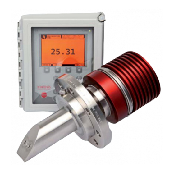
Vaisala K-PATENTS PR-21 Series User Manual (158 pages)
Process Refractometer
Brand:
Vaisala
| Category:
Measuring Instruments
| Size: 6.82 MB
Table of Contents
Table of Contents
3
1 About this Document
9
Version Information
9
Documentation Conventions
9
Table 1 Document Versions (English)
9
Trademarks
10
2 Product Overview
11
Figure 2 Refractometer Equipment PR-21-S
12
Safety
13
Figure 3 Labels
13
Storage Conditions, Packaging and Transportation
14
In-Line Refractometer Sensor
14
Figure 4 Sensor Structure
14
Figure 5 Image Detector System
15
3 Mounting
16
Choosing Sensor Mounting Location
16
Figure 6 Mounting Guide 1/2
17
Figure 7 Mounting Guide 2/2
18
Mounting Examples
19
Figure 8 Sandvik LPL and LPS
19
Figure 9 Flange LPL and LPS
20
Mounting Sensor
21
Figure 10 DIN, JIS and ANSI 150Lbs or 300Lbs Flanges
21
Pipe Mounting Checklist
22
Figure 11 Mounting Procedure
22
Checklist for Mounting in Tank, Vessel or Large Pipe
23
4 Indicating Transmitter DTR
24
Mounting Indicating Transmitter
24
Electrical Connections
25
Interconnecting Cable
25
Figure 12 Indicating Transmitter Dimensions and Mounting Feet Measures
25
Connecting Sensor
26
Figure 13 Wiring of PR-21-S with DTR
26
Connecting Indicating Transmitter
27
Figure 14 Opening Indicating Transmitter Front Panel
29
Figure 15 External Power Switch
30
Figure 16 Motherboard (AC Power)
31
Figure 17 Motherboard (24 V DC)
32
Power Terminals for AC Power
33
Power Terminals for 24 V DC Power
33
Relay Connections
34
Reset Button
36
Figure 18 Location of Reset Button
36
5 Prism Wash Systems
37
Prism Coating
37
Prism Wash with Integral Steam Nozzle
38
Figure 19 Mounting of Integral Steam Nozzles with DIN, JIS, ANSI and Sandvik Connections
39
Prism Wash with Integral High-Pressure Water Nozzle
40
Figure 20 Mounting Summary of Integral Prism Wash System
40
Figure 21 Mounting Drawing for Integral High-Pressure Wash System
42
Figure 22 Wiring Drawing: High-Pressure Wash System for Water
43
Prism Wash with Flow through Cells
44
Figure 23 Prism Wash with Flow through Cells
44
Recommended Wash Pressures and Times
45
Figure 24 Flow through Cell Nozzles
45
Table 2 Recommended Wash Pressures and Times
46
6 Startup and Use
47
Startup
47
Initial Check
47
Figure 25 Main Display Alternatives
47
Calibration Check
48
Testing Prism Wash
48
Using Indicating Transmitter
48
Keyboard Functions
49
Display Setup
50
Figure 26 DTR Keyboard and Main Menu for Sensor B
50
Figure 27 Display Setup Menu
51
Figure 28 Main Display Format Selection
51
Viewing System Information
52
Viewing Sensor Status
53
Optical Image
53
Figure 29 System Description
53
Diagnostic Values
54
Figure 30 Typical Optical Images
54
Figure 31 a Slope Graph
54
Temperature Measurement
55
Sensor Head Humidity
55
Sensor Verification
55
7 Configuration and Calibration
56
Configuring Output Signal Damping
56
Exponential Damping
56
Linear Damping
57
Figure 32 Exponential Damping
57
Slew Rate Limit
58
Figure 33 Linear Damping
58
Configuring Output Signal Hold Functionality
59
Figure 34 Slew Rate Damping
59
External Hold
60
Hold During Wash
60
Tolerance Time
60
Figure 35 Effect of Tolerance Time on Output
61
Hold Source Interactions
61
QF Threshold
61
Hold and Signal Damping
62
Configuring Refractometer System
62
Configuring Relays
62
Figure 36 Damping Stops During Hold
62
Figure 37 Relay Menu for Relay 1
63
Configuring Input Switches
64
Configuring Ma Outputs
66
Figure 38 Output Menu for Ma Output 1
67
Calibrating Concentration Measurement
68
Figure 39 Default Ma Output Values
68
Figure 40 Concentration Calibration Layers
69
Chemical Curve
70
Selecting Display Units and Display Decimals
70
Table 3 Chemical Curve Parameters
70
Field Calibration
71
Direct BIAS Adjustment
72
Entering Field Calibration Parameters
72
Figure 41 Using FIELD SAMPLE Soft Key
72
Configuring Prism Wash
73
Wash Cycle
73
Figure 42 Automatic Prism Wash Cycle
73
Figure 43 Wash Logic
75
Figure 44 Wash Cycle
77
Setting Prism Wash Parameters
78
Mechanical Zero Adjustment
79
Sensor Rangeability
80
Figure 45 Mechanical Zero Adjustment
80
Figure 46 Sensor Rangeability
80
8 Regular Maintenance
81
Checking the Sensor Humidity Level
81
Checking the Prism and Prism Gaskets
81
Disassembling and Assembling the Sensor
81
Disassembling the Sensor
82
Removing Electronic Cards PR-10301 and PR-10201
83
Figure 47 Ribbon Cable Connector
83
9 Troubleshooting
84
Hardware
84
Figure 48 Transmitter Card Positions
85
Figure 49 Motherboard PR-10600 and H1 Interface Card PR-10701
86
Blank Display
87
Figure 50 Troubleshooting Blank Display
87
Diagnostic Leds
88
Figure 51 Checking Power Supply
88
Table 4 Diagnostic Leds
89
Display Unreadable
90
Figure 52 Diagnostic LED Functions
90
Table 5 Hardware Troubleshooting
91
Troubleshooting Messages
91
Figure 48
93
Table 6 Measurement Troubleshooting
93
Table 7 Wash Troubleshooting
95
Diagnostic Message Priorities
96
10 Indicating Transmitter DTR Specifications
98
Compatibility
98
Transmitter Program Versions
98
Figure 53 Indicating Transmitter Serial Number Labels
98
Model Code
99
Indicating Transmitter Model Codes
99
Interconnecting Cable Model Code
99
Table 8 Indicating Transmitter DTR and STR Model Codes
99
Table 9 Interconnecting Cable Model Code
99
Transmitter Parts List
100
Specifications
100
Indicating Transmitter Specifications
100
Figure 54 Indicating Transmitter DTR and STR Parts (STR-Specific Parts in Italics)
100
Table 10 Indicating Transmitter Specifications
100
Interconnecting Cable Specifications
102
Table 11 Interconnecting Cable Specifications
102
11 Sensor Specifications
103
Model Codes
103
Table 12 PR-21-S Models
103
Table 13 Transmitter Models for 100
104
Table 14 Transmitter Models for 24 V DC
104
Table 15 Cables
104
PR-21-S Part List
105
Figure 55 Probe Parts
105
Sensor PR-21-S
107
Figure 56 Sensor
107
Standard Specifications
109
Table 16 Standard Specifications
109
PR-21-S Process Refractometers in Potentially Explosive Atmosphere
110
Equipment
110
Figure 57 Refractometer System PR-21
111
Intrinsically Safe Refractometers PR-21
112
Figure 58 FM Nameplate
112
Equipment
113
Figure 59 Refractometer System PR-21-S
113
Figure 60 IA Nameplate
114
Figure 61 Intrinsically Safe Parts
115
Figure 62 Warning Sticker
115
Intrisincally Safe Mounting
116
Figure 63 Intrinsically Safe Wiring, PR-21-S
117
Figure 64 Isolator Unit Wiring
118
Isolator/Barriers
118
12 Ethernet Connection Specification
119
Cable Requirements and Connection
119
Ethernet Cable Specification
119
Figure 65 Connecting DTR to Computer
119
Figure 66 Connecting DTR to LAN
120
Figure 67 Connecting DTR to Hub or Switch
120
Figure 68 Connecting DTR to WLAN
120
Connecting Ethernet Cable
121
Figure 69 Using Fiber Optics Ethernet
121
Connection Settings
123
IP Settings for DTR
123
Figure 70 Ethernet Connector on Underside of Front Panel
123
IP Settings for Stand-Alone Computer
124
Figure 71 Typical IP Configuration for Stand-Alone Laptop When Connected to DTR; Laptop Wireless (WLAN) Turned off
124
Testing Ethernet Connection
125
Troubleshooting Connection
126
Figure 72 Ping OK
126
Figure 73 Ping Error Message
126
Instrument Homepage
127
Remote Panel
128
Figure 74 Instrument Homepage Open in Browser
128
Sensor Verification Certificate
129
Collecting Data Using Ethernet
129
Communication Protocol
129
Figure 75 DTR Remote Panel
129
Request-Response Pair Specification
131
Table 17 Request-Response Pair Specification
131
Error Message Specification
133
13 Sensor Verification
135
Refractive Index N D Verification
135
Figure 76 Sample Holder: Part Number PR-5002
135
Handling R.I. Liquids
136
Verification Procedure
136
Figure 77 Verification, Pre-Verificaton Checks
137
Figure 78 Verification Display
137
Figure 79 Typical Optical Images
138
Figure 80 Verification in Progress
138
Sensor Verification Certificate
139
Figure 81 Verification Completed Successfully (here Only with One RI Liquid)
139
Figure 82 Instrument Verification Page Open in Browser
140
Figure 83 Instrument Verification Certificate
141
Corrective Action
142
Figure 84 Verification Failed
142
Figure 85 Finding Verification Information for Sensor Verification Form
143
14 Regulatory Compliance and Certifications
144
EC Declaration of Conformity for PR-21 Series of Refractometers
144
Declaration of Conformity for PR-21
146
Appendix A: Principle of Measurement
148
Figure 86 Refractometer Principle
148
Figure 87 Optical Images
149
Figure 88 Optical Image Detection
149
Appendix B: PR-21 Sensor Verification Form
150
Table 18 Verification Results Display
150
Appendix C: Field Calibration Form
151
Appendix D: DTR Command Selection Tree
152
Appendix E: Str/Divert Mode Command Selection Tree
153
Warranty
155
Technical Support
155
Recycling
155
Advertisement
Advertisement
Related Products
Vaisala K-PATENTS PR-21-S
Vaisala K-PATENTS PR-23-GP
Vaisala K-PATENTS PR-23-RP
Vaisala K-PATENTS PR-23-M
Vaisala K-PATENTS PR-23-MS
Vaisala K-PATENTS PR-23 AX Series
Vaisala K-PATENTS PR-23 FM Series
Vaisala K-PATENTS PR-23 IA Series
Vaisala K-PATENTS PR-23-SD-GP
Vaisala K-PATENTS PR-43-IA Series
Vaisala Categories
Transmitter
Measuring Instruments
Accessories
Weather Station
Test Equipment
More Vaisala Manuals
Login
Sign In
OR
Sign in with Facebook
Sign in with Google
Upload manual
Upload from disk
Upload from URL