
Subscribe to Our Youtube Channel
Related Manuals for SKF PVP-50-1G


Summary of Contents for SKF PVP-50-1G
- Page 1 Mounting and operating manual PVP lubrication pump Version Date of issue January 2016 Publication number 951-130-412 Languages Country/Countries...
-
Page 2: Table Of Contents
6. Activation ............14 Or an SKF Service Centre, the addresses of 6.1 General . - Page 3 EC Declaration of Incorporation in accordance with EC-Machinery Directive 2006/42/EC, Appendix II Part B The manufacturer SKF France SAS, 204, Bld Charles de Gaulle, B.P. 239 – 37540 St-Cyr-sur-Loire – FRANCE, declares herewith the confor- mity of the partly completed machine...
-
Page 4: Safety Instructions
Other use or use beyond this DANGER! purpose is considered unintended. Working on products that have Products of SKF must not be used in con- not been disconnected from the power junction with substances and mixtures clas- supply can cause serious injury or death sified as hazardous by the Annex I part 2-5 to persons. -
Page 5: Lubricants
You can request an overview of lubricant used for their intended purpose manufacturer's information on tests offered by SKF from our Service Center. and in accordance with the specifications the lubricants to be used in the of the installation instructions for the machinery. -
Page 6: Lubricants And The Environment
2.4 Lubricants and the 3 Construction and Lubricants are hazardous substance. It is environment essential to respect any safety instructions operation given in the lubricant safety data sheet. You can ask the manufacturer of the lubricant for the material safety data sheet. 3.1 General DANGER! The PVP lubrication pump is a pneumatic... -
Page 7: Operation
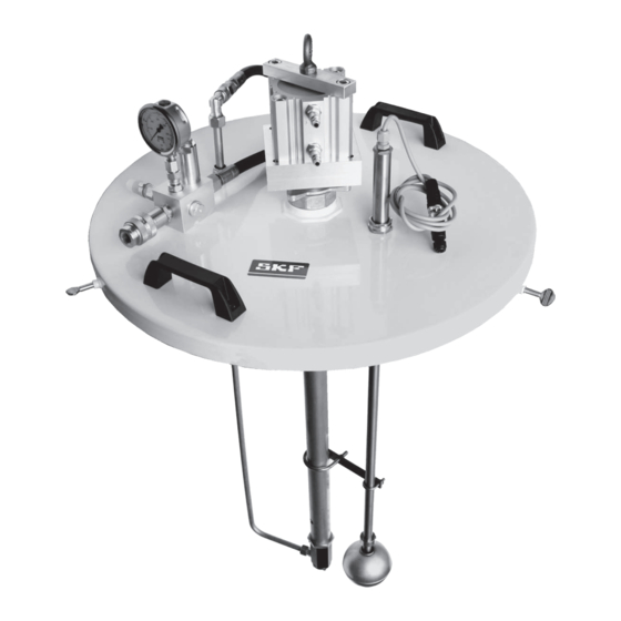
SKF offers different models of PVP pneu- bricant sucked towards the outlet. The lubri- matic pumps. It is also possible to request cant then gets through a filter to ensure special models. - Page 8 Fig. 1 PVP pump for oil or fluid grease Ø20 PVP pump for oil (50 or 200 l) or fluid grease (50 or 180 kg) 1 Lifting eye 2 Pneumatic cylinder 3 Pressure limiter 4 Manometer 5 Filter 6 Pump 7 Level contact, minimum level check 8 Air inlets, hoses with quick-release coupling 9 Grease output...
- Page 9 Fig. 2 PVP pump for grease Ø20 PVP grease pump (50 or 180 kg) 1 Lifting eye 2 Pneumatic cylinder 3 Pressure limiter 4 Manometer 5 Filter 6 Pump 7 Level contact, minimum level check 8 Follower cylinder 9 Air inlets, hoses with quick-release coupling 10 Grease output 11 Level contact connector 12 Discharge volume adjustment plug...
-
Page 10: Installation Instructions
4. Installation 4.2 Pump setting The compressed air quality must comply instructions SKF recommends adjusting the pump dis- with purity class 5 defined by DIN ISO The pneumatic pump described in this docu- charge volume before setting the pump 8573-1: ment may only be installed, operated, main- (†... -
Page 11: Electric Connection
4.4 Electric connection Fig. 5 conveyed. In addition, the lubrication net- work must be secure with a safety valve BN/1 against unacceptable overpressure. All components of the lubrication network such as tubes, hoses, isolation valves, dis- tributors, connections etc. must be properly DANGER! BU/4 cleaned before installation. - Page 12 DANGER! Centralised lubrication systems must be absolutely leak-free. Lubricant leakage is a source of danger. There is a risk of falling and injury. During installa- tion, activation, maintenance and repair the centralized lubrication systems must be checked for lubricant leaks. Leaking points must be immediately plugged.
-
Page 13: Transport, Delivery And Storage
5.1 Transport 5.3.3 Storage – general information SKF products are packaged in accordance with the regulations of the recipient country • Ensure that no dust gets into stored prod- and in accordance with DIN ISO 9001. Our ucts by wrapping them in plastic film products must be transported with care. -
Page 14: Activation
6. Activation Discharge volume at 3cm /cycle Fig. 6 Suction is carried out at the upper inlet († fig. 6). The other two inlets are blocked 6.1 General by a screw plug and a seal. In case of an oil The pneumatic pump described, mounted or fluid grease pump, the suction inlet is on the lubricant drum operates automati-... - Page 15 • If you remove the pump manually, make sure to place it in a clean place to avoid contamination. • SKF recommends to clean the pump cover before removing it from the drum to mini- mize the impact of environmental pollution.
-
Page 16: Shutdown
CAUTION! SKF is not liable for damage caused by im- The described product may be proper installation, maintenance, or repair under pressure when it is being operat- work. -
Page 17: Failures
9. Failures You must not dismantle the prod- Only original SKF spare parts may uct or parts of the product during be used. It is prohibited for the Table 2 gives an overview of possible mal- the warranty period. Doing so invalidates operator to make alterations to the functions and their causes. -
Page 18: Technical Data
10. Technical data Table 3 Technical data PVP pump Pump type: dual-stroke pneumatic pump Air feed pressure min 3 bar / max 8 bar Maximum air consumption 50 l/min Pressure ratio 45:1 Maximum operating pressure 300 bar Operating temperature -10 to +70 °C Maximum pump speed 6 cycles/min Maximum discharge volume... -
Page 19: Spare Parts
11. Spare parts Table 4 List of spare parts PVP-50-1G pump Reference Designation PVP-2014-50L-02 50 kg drum cover PT.1004 Level sensor PVP-2027-50L-01 50 kg follower piston UH2801.12 0 to 400 bar manometer MS110.5.10 5/10 filter cartridge 161-210-008 Pressure relief valve... - Page 20 Important information on product usage SKF and Lincoln lubrication systems or their components are not approved for use with gases, liquefied gases, pressurized gases in solution and fluids with a vapor pressure exceeding normal atmospheric pressure (1 013 mbar) by more than 0,5 bar at their maximum permissible temperature.
Need help?
Do you have a question about the PVP-50-1G and is the answer not in the manual?
Questions and answers