SKF P212 Assembly Instructions Manual
Hide thumbs
Also See for P212:
- Installation instructions manual (40 pages) ,
- Assembly instructions manual (48 pages)

Related Manuals for SKF P212


Summary of Contents for SKF P212
- Page 1 Assembly Instructions Pump P212 Created on: 29.06.2023 Document no.: 951-171-084-EN Version: Read these instructions before nstallation or start-up of the product and keep them readily available for later consultation!
- Page 2 The special technical documents were prepared following Annex VII part B. Upon justifiable request, these special technical documents can be forwarded electronically to the respective national authorities. The authorized company for the compilation of the technical documentation is SKF (U.K.) Limited, 2 Canada Close, Banbury, Oxfordshire, OX16 2RT, GBR.
- Page 3 Description of the essential health and safety requirements according to 2006/42/EC, Annex I, which have been applied and fulfilled: Table 1 Appendix to Declaration of Incorporation Piston pumps with reservoir, with/without external motor, without control unit Types: P205, P208, P212, P215, P230, ZPUxx, JM, FF, FB, FK, RA, TA, TB No.: Essential health and safety requirement Applicable:...
-
Page 4: Masthead
Training www.skf.com/lubrication We conduct detailed training in order to enable maximum safety and efficiency. We recommend taking advantage of this Berlin Plant training. For further information, contact your authorized SKF Motzener Strasse 35/37 dealer or the manufacturer. 12277 Berlin Germany Tel. -
Page 5: Table Of Contents
4.4 Ultrasonic sensor ..............16 4.4.1 Full signal/low-level signal/minimum clearance .. 16 4.4.2 Ultrasonic sensor 664-85313-9 ......17 4.5 Type identification code for pump P212 ......19 5. Delivery, returns, storage ............20 5.1 Delivery ..................20 5.2 Return shipment..............20 5.3 Storage .................. -
Page 6: Safety Alerts, Visual Presentation, And Layout
1. Instruction steps: These indicate a chronological sequence Safety alerts, visual of instruction steps. The numbers of the steps are in bold and are followed by a period. If a new activity follows, the presentation, and layout numbering starts again at “1.” –... -
Page 7: Safety Instructions
Only • If protective and safety equipment has to be dismantled, it original SKF spare parts and SKF accessories may be used. must be reassembled immediately after finishing the work, • Any unclear points regarding proper condition or correct and then checked for correct function. -
Page 8: Foreseeable Misuse
1.6 Foreseeable misuse 1.10 Safety markings on the product Any usage of the product other than as specified in this manual Table 2 is strictly prohibited. Particularly prohibited are: • Use of non-specified consumables, contaminated lubricants, Risk of dangerous electrical voltage (on the motor terminal box) or lubricants with air inclusions. -
Page 9: Notes On Ce Marking
1.12 Notes on CE marking 1.19 Assembly, maintenance, fault, repair CE marking is effected following the requirements of the applied directives requiring a CE marking: Prior to the start of this work, all relevant persons must be notified of it. At a minimum, the following safety measures must •... -
Page 10: Residual Risks
1.21 Residual risks Table 3 Residual risks Residual risk Possible in lifecycle Avoidance / Remedy Personal injury / property damage due A B C G H K • Unauthorized persons must be kept away. Nobody is to falling of hoisted parts allowed to be present below hoisted parts. -
Page 11: Lubricants
Solid lubricants may only be used after prior consultation with make the selection in consultation with the supplier of the SKF. When solid lubricants are used in lubrication systems, the lubricant. If you have no or little experience in selecting following rules generally apply: lubricants for lubrication systems, please contact us. -
Page 12: Overview, Functional Description
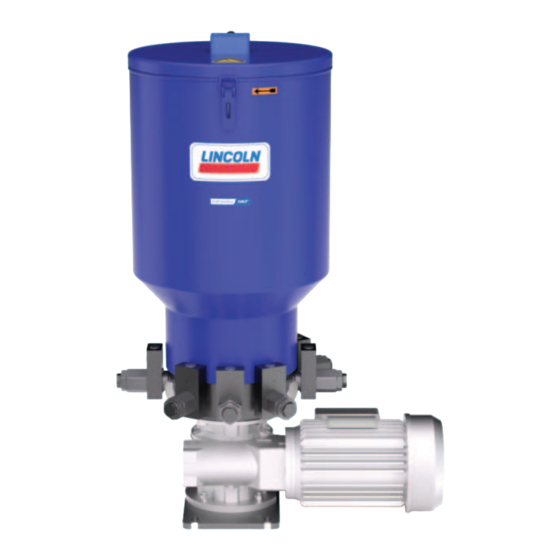
3.2 Mode of operation 3. Overview, functional Fig. 3 description 3.1 Overview Fig. 2 Mode of operation Legend to Figure 3: Main components 1 Eccentric shaft 2 Pump elements Legend to Figure 2: 1 Ultrasonic sensor The gearbox (fig. 3/5) reduces the speed of the motor (fig. 3/4) 2 Reservoir with stirring paddle to the speed required for the eccentric shaft (fig. -
Page 13: Technical Data
4. Technical data 4.1 Technical data Table 4 Technical data Designation Value Operating temperature Min. -20 °C Max. +70 °C Operating pressure Max. 350 bar Mounting position Upright, with reservoir at top Reservoir size 30 L Minimum mounting dimensions – Reservoir design XYN Minimum space required 540 mm (width) / 880 mm (height) / 400 mm (depth) –... -
Page 14: Delivery Rate
4.2 Delivery rate NOTICE Damage / malfunction Possible damage to the machine due to influencing variables Influencing variables such as: ambient temperature, back pressure, type of pumped fluid, NLGI Grade of the pumped fluid, and type of connection of the pump's multi-range motor, can cause the delivery rate to deviate from the range specified on the delivery rate charts. -
Page 15: Motor
4.3 Motor Table 5 Pump type P212 Item number 245-13996-1 FEN motor code no. U00-00 Parameter Value Voltage 220-240 / 380-415 V 243-277 / 420-480 V Frequency 50 Hz 60 Hz Rated capacity 0.55 kW 0.65 kW Rated speed 1410/21 rpm... -
Page 16: Ultrasonic Sensor
4.4 Ultrasonic sensor 4.4.1 Full signal/low-level signal/minimum clearance Fig. 5 Full signal/low-level signal/minimum clearance Table 6 Technical data (full signal/low-level signal/minimum clearance) Reservoir Switching points 30XYBU A: Full signal approx. 65 mm B: Low-level signal approx. 420 mm NOTE The minimum clearance between the lubricant and the ultrasonic sensor is 60 mm. If this distance is not maintained, undefined switching states of the ultrasonic sensor could result in faulty measurement results. -
Page 17: Ultrasonic Sensor 664-85313-9
4.4.2 Ultrasonic sensor 664-85313-9 Table 7 Technical data Parameter Value Blind zone 0-65 mm Sensing range 600 mm Ultrasonic frequency Approx. 400 kHz Sonic frequency 3.7 Hz Resolution 0.18 mm Accuracy ± 1 % Reproducibility ± 15 % Sensing range in centimeters The dark gray areas (A) indicate the range in which the standard reflector (a tube) is reliably detected. - Page 18 Table 8 Electrical connection Color (IEC 60757) Brown (BN) Blue (BU) Black (BK) White (WH) D3 / Com Gray (GY) Table 9 Display of the circuit states Parameter Switching points Display of the LEDs D1 (up D2 (up to 10/21) (from 10/21) to 10/21) (from 10/21)
-
Page 19: Type Identification Code For Pump P212
4.5 Type identification code for pump P212 P212 - M G 067 - 30 XYBU - 3 KR12 - 380 - 480 Pump type: P212 Pump P212 for grease or oil Drive: MG067 Large flange / transmission ratio 67:1 Reservoir assembly:... -
Page 20: Delivery, Returns, Storage
5.5 Storage conditions for products filled 5. Delivery, returns, storage with lubricant 5.1 Delivery For products filled with lubricant, the permitted storage temperature range is: After receipt of the shipment, it must be inspected for any minimum + 5 °C [+41 °F] shipping damage and for completeness according to the maximum... -
Page 21: Assembly
6. Assembly NOTE Connect the cables in such a way that no tensile forces can Observe the safety instructions and the technical data in this be transferred to the product. manual. Additionally, during assembly pay attention to the following: • Only qualified and authorized technical personnel may install 6.2 Important note regarding installation the products described in this manual. -
Page 22: Installing The Pump Elements
6.3 Installing the pump elements Fig. 10 Fig. 9 Correct position of the pump elements NOTICE Possible damage to the pump Incorrectly installed pump elements can result in damage to the pump • Make sure that every pump element is sitting correctly in the groove on the driver ring (Fig. -
Page 23: Setting The Pump Elements
6.4 Setting the pump elements Table 10 Delivery rate NOTE KR12 The delivery rate of the pump elements can also be set during operation <Co ntent> R = 25 mm 100 % R = 24 mm 90 % Fig. 11 R = 23 mm 80 % R = 22 mm... -
Page 24: Filling The Reservoir
5. Switch on the pump. 6.5 Filling the reservoir 6.5.1 Filling via the reservoir cover 6.5.2 Filling via the fill connection Automatic filling: WARNING The filling pump is controlled by the full and low-level signals of Hand injury from stirring paddle the pump, combined with a higher-level control. -
Page 25: First Start-Up
7. First start-up NOTICE Damage Possible damage to the machine Fill the delivery lines with lubricant, and lubricate the lubrication points manually. Otherwise, it is possible that bearings will be damaged by a lack of lubrication. Ensure that all parameters, variables, and consumables are correctly configured and available. Any identified deviations must be resolved immediately. -
Page 26: Operation
8. Operation 8.1 Daily start-up The activities to be performed in normal operation are listed below 8.1.1 Inspections For the activities listed in section 7. First start-up, the owner- operator must define suitable inspection periods according to the specific situation in which in the pump is operated 8.1.2 Filling the reservoir during operation The reservoir is filled as described in section 6.5 Filling the reservoir... -
Page 27: Maintenance
9. Maintenance Careful and regular maintenance is required in order to detect and remedy possible faults in time. The operator must always determine the specific intervals according to the operating conditions, review them regularly, and adjust them where necessary. If necessary, copy the table for regular maintenance activities. -
Page 28: Cleaning
10. Cleaning 10.1 Basics Cleaning should be carried out in accordance with the operator's own company rules, and cleaning agents and devices and the personal protective equipment to be used should likewise be selected in accordance with those rules. Only cleaning agents compatible with the materials may be used for cleaning. -
Page 29: Faults, Causes, And Remedies
11. Faults, causes, and remedies WARNING Electric shock Disconnect the product from the power supply before any work on electrical components • Assembly, maintenance, and repair work may only be performed by qualified technical personnel • De-energize the product prior to beginning work •... -
Page 30: Shutdown, Disposal
12. Shutdown, disposal 12.1 Temporary shutdown Temporary shutdowns should be done by a course of action to be defined by the operator. 12.2 Permanent shutdown, disassembly Permanent shutdown and disassembly of the product must be planned properly by the operator and conducted in compliance with all applicable laws and regulations. -
Page 31: Spare Parts
13. Spare parts 13.1 Ultrasonic sensor Table 15 Designation Pcs. Item number Ultrasonic sensor for 30 L reservoir 664-85313-9 13.2 Pump element KR7 Fig. 13 Pump element KR7 Table 16 Designation Pcs. Item number Pump element KR7, complete 660-77835-1 Comprising: Outlet port with check valve, complete Sealing ring Pump element KR7... -
Page 32: Pump Element Kr12
13.3 Pump element KR12 Fig. 14 Pump element KR12 Table 17 Designation Pcs. Item number Pump element KR12, complete 660-77619-1 Comprising: Outlet port with check valve, complete Sealing ring Pump element KR12 13.4 Motor Table 18 Designation Pcs. Item number Multi-range motor 0.55 / 0.65 kW, 380-415 / 420-480 V with gearbox i=67:1 245-13996-1 13.5 Retainer plate, reservoir, stirring paddle... -
Page 33: Appendix
14. Appendix 14.1 Cable colors in accordance with IEC 60757 Table 21 Cable colors in accordance with IEC 60757 Abbreviation Color Abbreviation Color Abbreviation Color Abbreviation Color Black Green White Pink Brown Yellow Orange Turquoise Blue Violet Gray GNYE Green/Yellow RDWH Red/White Gold... - Page 34 Notes / Notizen / Apuntes...
- Page 35 Notes / Notizen / Apuntes...
- Page 36 ® SKF and Lincoln are registered trademarks of the SKF Group. ™ eLube is a trademark of the SKF Group. © SKF Group 2023 Reprint or reproduction of the contents of this information - even in part - is permitted only with SKF's prior written consent.
Need help?
Do you have a question about the P212 and is the answer not in the manual?
Questions and answers