
Related Manuals for XFP XFP501E/X

Summary of Contents for XFP XFP501E/X
- Page 1 NETWORKABLE ANALOGUE ADDRESSABLE FIRE ALARM CONTROL PANEL Single Loop 16 Zone Version Part Nos. XFP501E/X, XFP501E/H engineering manual Approved Document No. DFU1200510 Rev 3...
-
Page 2: Table Of Contents
However, no responsibility can be accepted by the manufacturer for any inaccuracies or for any misinterpretation of an instruction or guidance note. Manufacturer: Computionics Limited (C-TEC), Challenge Way, Martland Park, Wigan, Lancashire WN5 0LD. www.c-tec.com Niederlassung Deutschland: C-TEC Germany Limited, Virchowstr. 32, D-33332 Gϋtersloh. www.c-tec-germany.de XFP ENGINEERING MANUAL • Approved Document No. DFU1200510 Rev 3 • Page 2 of 36... -
Page 3: Important Notes
Anti-static handling guidelines Always observe appropriate electro-static handling precautions prior to handling the panel’s PCBs or any other static-sensitive components. XFP ENGINEERING MANUAL • Approved Document No. DFU1200510 Rev 3 • Page 3 of 36... -
Page 4: Key Features
If required, the panel can be configured to sit on a non-redundant network of up to eight interconnected XFP main panels (any variant), OR it can have up to eight XFP repeaters connected to one non- networked XFP main panel. If you wish to utilise either of these options, the panel will require a separately available Network Communication Card (Part No. -
Page 5: Installation And Wiring
Store the PCBs in a clean, dry place which is free from vibration, dust and excessive heat. Retaining the PCBs in a suitable cardboard box will also guard them against mechanical damage. XFP ENGINEERING MANUAL • Approved Document No. DFU1200510 Rev 3 • Page 5 of 36... -
Page 6: Mounting The Base Onto A Wall
Mains feed from the Main Distribution Board (A) to the Panel (C), providing it meets the appropriate wiring ≥ 1.0 mm < 2.5 mm regulations (see drawing right). XFP ENGINEERING MANUAL • Approved Document No. DFU1200510 Rev 3 • Page 6 of 36... -
Page 7: Connecting Mains To The Power Supply Pcb
LEAST 5 MINUTES BEFORE REMOVAL & HANDLING. Battery Fuse (F2) Connector Cable Socket (PL1) Connect other end of lead to the rear of Main Control PCB. XFP ENGINEERING MANUAL • Approved Document No. DFU1200510 Rev 3 • Page 7 of 36... -
Page 8: Analogue Addressable Loop Wiring
To ensure a reliable system, it should be designed and maintained to local design and installation regulations. The XFP has loop isolators included in the panel, and loop isolators should be included in the loop wiring. A single short circuit fault will now only disable devices in the section of wiring between isolators. -
Page 9: Connecting The Analogue Loop To The Main Control Pcb
DISPOSE OF USED BATTERIES ACCORDING PRECAUTIONS BEFORE TO THE MANUFACTURERS INSTRUCTIONS. INSTALLATION INSTRUCTIONS HANDLING FOR OPERATIONAL DETAILS PLEASE CONSULT THE MAINTENANCE MANUAL and PL1 on PSU PCB XFP ENGINEERING MANUAL • Approved Document No. DFU1200510 Rev 3 • Page 9 of 36... -
Page 10: Conventional Sounder Circuit Wiring
The three auxiliary outputs (Relays 1, 2 and 3) can be programmed using the panel’s PC programming software tools to operate as required but their default operations are: XFP ENGINEERING MANUAL • Approved Document No. DFU1200510 Rev 3 • Page 10 of 36... -
Page 11: Remote Pc Connection
Location of large Connection of leads sized batteries sized batteries sized batteries to Power Supply PCB typically 1.2 Ah typically 2.1 Ah typically 3.0 Ah XFP ENGINEERING MANUAL • Approved Document No. DFU1200510 Rev 3 • Page 11 of 36... -
Page 12: Network/Repeater Wiring (Optional)
Key features of the non-redundant network protocol when used for interconnecting XFP main panels: • Allows the interconnection of up to eight XFP main panels (any mix of single loop 16 zone XFPs and 1 and 2 loop 32 zone XFPs) •... - Page 13 SPUR WIRING SPUR WIRING SPUR WIRING SPUR WIRING NOT ALLOWED NOT ALLOWED NOT ALLOWED NOT ALLOWED NOT ALLOWED NOT ALLOWED NOT ALLOWED NOT ALLOWED NOT ALLOWED XFP ENGINEERING MANUAL • Approved Document No. DFU1200510 Rev 3 • Page 13 of 36...
-
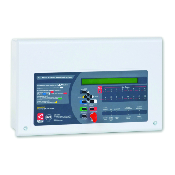
Page 14: Controls And Indicators
Delays Running Lit yellow when one or more output delay has been programmed into the panel. Flashes yellow when one or more output delay is running. XFP ENGINEERING MANUAL • Approved Document No. DFU1200510 Rev 3 • Page 14 of 36... - Page 15 Starts the panel’s investigate timer function (access levels 2 & 3 only) Keyswitch control Turning the keyswitch to the armed position (I) gives the user instant access to access level 2 (authorised user level). XFP ENGINEERING MANUAL • Approved Document No. DFU1200510 Rev 3 • Page 15 of 36...
-
Page 16: Commissioning And Programming
Note that the panel’s two auxiliary inputs can be programmed to function in a multitude of ways using the special cause and effects options available in the XFP programming software. XFP ENGINEERING MANUAL • Approved Document No. DFU1200510 Rev 3 • Page 16 of 36... -
Page 17: Access Levels Menu Tree
BLINK DETECTORS LEDS INTENSIVE DEVICE MONITOR LOOP TEST DISPLAY DATABASE VERSION NUMBERS SHOW PSU STATS ENABLE/DISABLE EARTH FAULT SHOW LOOP CURRENT SHOW DISCOVERY EEPROM SHOW NETWORKED EVENTS XFP ENGINEERING MANUAL • Approved Document No. DFU1200510 Rev 3 • Page 17 of 36... -
Page 18: How To Enter Access Level Three
• Connect the panel to a compatible PC for system programming • Set the panel up to belong to a non-redundant network of eight XFP main panels, or allow it to have up to eight XFP repeaters connected to it •... - Page 19 (4) buttons, enter the new four digit access level 2 code. After the fourth digit has been entered, the panel will request you confirm the new code by re-entering it: XFP ENGINEERING MANUAL • Approved Document No. DFU1200510 Rev 3 • Page 19 of 36...
- Page 20 Selecting this menu option takes you to the network functions submenu where you can configure the panel to be part of a non-redundant network of up to eight XFP main panels, OR allow it to have up to eight XFP repeaters connected to it. This option is only available if you have a network communication card fitted at the panel (see pages 12 &...
- Page 21 0 changed; 0 removed; 112 total devices Auto learn completed Press the Escape button to return to the Commissioning Functions submenu. XFP ENGINEERING MANUAL • Approved Document No. DFU1200510 Rev 3 • Page 21 of 36...
- Page 22 1 to 10 on loop 1 and the second line shows the type of devices fitted at addresses 11 to 20. The letters displayed will be dependent on the type of device at that address location. XFP ENGINEERING MANUAL • Approved Document No. DFU1200510 Rev 3 • Page 22 of 36...
- Page 23 When the SHOW CALIBRATION PROBLEMS prompt is accepted, details of the first detector with a cal- ibration problem will appear. For example: Loop: 1 Device: 23 :Calibration issue Turn ON output channels 1&3 XFP ENGINEERING MANUAL • Approved Document No. DFU1200510 Rev 3 • Page 23 of 36...
- Page 24 When the desired time is displayed, press the Accept button again and you will be returned to the commissioning functions submenu. XFP ENGINEERING MANUAL • Approved Document No. DFU1200510 Rev 3 • Page 24 of 36...
- Page 25 The window will now move to the next sounder group allowing further enablements or disablements to be made. Alternatively, to return to the previous menu press the Escape button. XFP ENGINEERING MANUAL • Approved Document No. DFU1200510 Rev 3 • Page 25 of 36...
- Page 26 Accept button to select the desired option. Alternatively, to return to the previous menu press the Escape button. XFP ENGINEERING MANUAL • Approved Document No. DFU1200510 Rev 3 • Page 26 of 36...
- Page 27 Output channels 1 and 2 asserted Output channel 3 asserted Output channels 3 and 1 asserted Output channels 2 and 3 asserted All output channels asserted XFP ENGINEERING MANUAL • Approved Document No. DFU1200510 Rev 3 • Page 27 of 36...
- Page 28 Should you wish to test additional panel relays, use the buttons to change the panel relay’s number accordingly. To return to the main Engineer Functions submenu, press the Escape button. XFP ENGINEERING MANUAL • Approved Document No. DFU1200510 Rev 3 • Page 28 of 36...
- Page 29 To end the test press the Escape button at any time. XFP ENGINEERING MANUAL • Approved Document No. DFU1200510 Rev 3 • Page 29 of 36...
- Page 30 Good polls: 592, Bad polls: 3 To return to the analogue value window press the More Information button again. To exit the INTENSIVE DEVICE MONITOR function press the Escape button. XFP ENGINEERING MANUAL • Approved Document No. DFU1200510 Rev 3 • Page 30 of 36...
- Page 31 (zone and device text). When the DISPLAY DATABASE? prompt is accepted, you will be prompted to enter the loop you wish to view the database of: Loop:-1 XFP ENGINEERING MANUAL • Approved Document No. DFU1200510 Rev 3 • Page 31 of 36...
- Page 32 Mains = OK Batt = OK Charge = OK Batt R = OK Mains = OK Batt = OK Charge = OK To return to the Engineering Functions submenu, press the Escape button. XFP ENGINEERING MANUAL • Approved Document No. DFU1200510 Rev 3 • Page 32 of 36...
- Page 33 When accepted, a window similar to the following will appear: F F F F F T F F F F F T T F F F T = Event True; F = Event False XFP ENGINEERING MANUAL • Approved Document No. DFU1200510 Rev 3 • Page 33 of 36...
-
Page 34: Maintenance
Both batteries should be renewed if there is any doubt about their integrity. The memory log should be checked for any faults that have automatically cleared, and these dealt with accordingly. XFP ENGINEERING MANUAL • Approved Document No. DFU1200510 Rev 3 • Page 34 of 36... -
Page 35: Standby Battery Calculation Guide
Standby Time in Ah = 1.25 x [(0.5 x 0.8) + 24 x (0.025 + 0.042)] = 2.51Ah Therefore, batteries with at least 2.51Ah capacity are required. XFP ENGINEERING MANUAL • Approved Document No. DFU1200510 Rev 3 • Page 35 of 36... -
Page 36: Technical Specification
LPCB Cert No.: 176b LPCB Reference Nos.: XFP501E/H (176b/05), XFP501E/X (176b/06) DOP Nos.: DOP0000035 (XFP501E/H), DOP0000034 (XFP501E/X) Tested to: EN54-2:1997 + A1:2006 & EN54-4:1997 + A1:2002 + A2:2006 CPR Certificate Nos: 0832-CPR-F1585 (XFP501E/H), 0832-CPR-F1586 (XFP501E/X) XFP ENGINEERING MANUAL • Approved Document No. DFU1200510 Rev 3 • Page 36 of 36...
Need help?
Do you have a question about the XFP501E/X and is the answer not in the manual?
Questions and answers