Table of Contents
Advertisement
Installation
Start-Up
Maintenance
Parts
Warranty
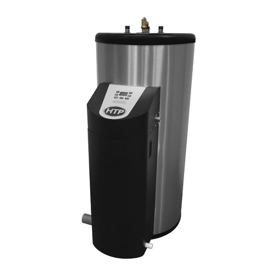
PH76* Models
* "LP" Denotes Propane Gas
"S" Denotes Solar Model
This manual must only be used by a qualified installer / service technician. Read all instructions in this manual before installing.
Perform steps in the given order. Failure to do so could result in substantial property damage, severe personal injury, or death.
Improper installation, adjustment, alteration, service, or maintenance could void product warranty and cause property
damage, severe personal injury, or death.
California Proposition 65 Warning: This product contains chemicals known to the State of California to cause cancer, birth
defects, or other reproductive harm.
HTP reserves the right to make product changes or updates without notice and will not be held liable for typographical errors
in literature.
The surfaces of these products contacted by potable (consumable) water contain less than 0.25% lead by weight as required
by the Safe Drinking Water Act, Section 1417.
NOTE TO CONSUMER: PLEASE KEEP ALL INSTRUCTIONS FOR FUTURE REFERENCE.
272 Duchaine Blvd.
Light Commercial
Gas Fired Water Heaters
New Bedford, MA 02745
Phoenix
www.htproducts.com
lp-441 Rev. 004 Rel. 000 Date 7.2.21
Advertisement
Table of Contents

Subscribe to Our Youtube Channel
Related Manuals for HTP Phoenix PH76


Summary of Contents for HTP Phoenix PH76
- Page 1 California Proposition 65 Warning: This product contains chemicals known to the State of California to cause cancer, birth defects, or other reproductive harm. HTP reserves the right to make product changes or updates without notice and will not be held liable for typographical errors in literature.
- Page 2 WARNING: If the information in these instructions is not followed exactly, a fire or explosion may result causing property damage, personal injury or death. • Do not store or use gasoline or other flammable vapors and liquids in the vicinity of this or any other appliance. WHAT TO DO IF YOU SMELL GAS •...
- Page 3 AHJ. NOTE: HTP reserves the right to modify product technical specifications WARNING indicates a potentially hazardous situation which, if not and components without prior notice.
-
Page 4: Table Of Contents
G. Filling the Heater H. Applications From the Uniform Plumbing Code 2000 - Section 510 - Part 5 - Venting Protection From Damage A. General B. Approved Materials for Exhaust Vent and Intake Pipe 1. Water heaters generating a glow, spark or flame capable of igniting flammable vapors may be installed in a garage, provided the pilots, C. -
Page 5: Part 1 - General Safety Information
WARNING Part 1 - General Safety Information This water heater is approved for indoor installations only and is This water heater must be installed by a licensed plumber, licensed not intended for use as a pool heater. Clearance to combustible gas fitter, and/or professional service technician. -
Page 6: Improper Combustion
DO NOT alter or modify the appliance or appliance controls. Altering heater. any HTP water heater with parts not manufactured by HTP WILL NOTE: When inquiring about service or troubleshooting, reference INSTANTLY VOID the water heater warranty and could result in the model and serial numbers from the water heater rating label. -
Page 7: Freeze Protection
In USA NOTE: HTP DOES NOT WARRANT THE APPLIANCE AGAINST FREEZE- de-rate by: RELATED DAMAGE. NOTES: G. Water Temperature Adjustment Canada: Elevations between 2000 - 4500 ft (610 - 1372 m), de-rate by 10%. -
Page 8: Part 2 - Before You Start
Neutralizers can be installed products, places, and conditions listed in this manual in the field by the installer and purchased from HTP (p/n 7450P-212). It is also very important not to expose the condensate line to freezing •... -
Page 9: Leveling
• NOTE: To prevent condensing in the fan, it is recommended to avoid prolonged exposure to temperatures below 45 All appliances eventually leak. Locate the appliance where any 2. Check for nearby connections to: leakage from the relief valve, related piping, tank, or connections •... -
Page 10: Residential Garage And Closet Installations
Alcove Installations Alcove installations have the same minimum dimensions as closet installations, except the installation must be completely open to the room at a distance no greater than 18 in. (457 mm) from the front of the appliance and the room must be at least three (3) times the size of the alcove. -
Page 11: Direct Vent Of Exhaust And Intake
The exhaust discharged by this water heater may be very hot. Failure to provide an adequate supply of fresh combustion air can Avoid touching or other direct contact with the exhaust gases of cause poisonous flue gases to enter the living space, resulting the vent termination assembly. -
Page 12: Removing A Heater From A Common Vent System
7. Any improper operation of the common venting system should Areas Likely Have Products to Avoid be corrected to conform to the National Fuel Gas Code, ANSI Contaminants Z223.1. When resizing any portion of the common venting system, Dry cleaning / laundry areas and the system should approach the minimum size as determined using Spray cans containing fluorocarbons establishments... - Page 13 T&P AUXILIARY RETURN HOT OUTLET 4.000 8.000 COLD INLET ANODE MODEL # GALLONS PH76-50 44-3/4" LP-441-D PH76-60 52-5/8" 33" 33" 6-3/4" 23" 32-1/2" 06/29/21 PH76-80 69" SYSTEM SHIPPING MAX. INPUT INLET/OUTLET AUXILIARY MODEL # INTAKE/EXHAUST LINE RELIEF WEIGHT TEMPERATURE MODULATION SIZE CONN.
-
Page 14: Part 4 - Piping
Part 4 - Piping Failure to follow the instructions in this section WILL VOID the Never connect auxiliary connections to any system that uses glycol warranty and may result in property damage, severe personal injury, or other solutions formulated for hydronic systems. These auxiliary or death. -
Page 15: Scalding
To avoid water damage or scalding due to relief valve operation: An ASSE 1017 or ASSE 1070 temperature limiting or mixing valve is • Discharge line must be connected to relief valve outlet and recommended in installations servicing disabled or elderly persons, run to a safe place of disposal. -
Page 16: Applications
H. Applications Figure 4 - Piping with Recirculation Line and Thermostatic Mixing Valve Piping NOTES: 1. Minimum pipe size should match connection size. Upsize pipe accordingly if greater flow is required. 2. A thermal expansion tank suitable for potable water must be sized and installed within this piping system between the backflow preventer and the cold water inlet. - Page 17 Figure 5 - Piping with Air Handler on Side Figure 6 - Additional View with Air Handler on Side NOTES: 1. Minimum pipe size should match connection size. Upsize pipe accordingly if greater flow is required. 2. A thermal expansion tank suitable for potable water must be sized and installed within this piping system between the backflow preventer and the cold water inlet.
-
Page 18: Part 5 - Venting
Part 5 - Venting The heater must be vented as detailed in this section. Ensure exhaust vent and intake piping complies with these instructions regarding vent system. Inspect finished exhaust vent and intake piping thoroughly to ensure all joints are well secured, airtight, and comply with all applicable code requirements, as well as the instructions provided in this manual. -
Page 19: Approved Materials For Exhaust Vent And Intake Pipe
B. Approved Materials for Exhaust Vent and Intake Pipe Standards for Installation In: Item Material United States Canada Pipe and Fittings Approved for Intake ONLY ABS* ANSI/ASTM D2661 ANSI/ASTM D2661 PVC Schedule 40/80 UL-1738 or ANSI/ASTM D1785 PVC-DWV Schedule 40/80 UL-1738 or ANSI/ASTM D2665 UL-1738 or ULC-S636 Pipe Approved for... -
Page 20: Exhaust Vent And Intake Pipe Location
D. Exhaust Vent and Intake Pipe Location INSIDE CORNER DETAIL FIXED OPERABLE CLOSED FIXED CLOSED OPERABLE LP-179-CC 03/28/17 Exhaust Vent Terminal Intake Pipe Terminal Area Where Intake Terminal Is Not Permitted Figure 7 - Exit Terminals for Direct Vent Systems - ANSI Z223.1 / NFPA 54 for US and CAN/CSA B149.1 for Canada DESCRIPTION CANADA Clearance above grade, veranda, porch, deck, or balcony... -
Page 21: Exhaust Vent And Intake Pipe Sizing
E. Exhaust Vent and Intake Pipe Sizing G. Exhaust Vent and Intake Pipe Installation 1. The exhaust vent and intake pipe size is 2”. 2. The total equivalent length of exhaust vent and intake pipe should not exceed 150 feet. All joints of positive pressure vent systems must be sealed completely a. -
Page 22: Applications
The letters shall be sized equal to a minimum of the pipe diameter. However, for piping with a diameter exceeding two inches, said lettering does not need to be larger than two inches. The following table lists optional exhaust/intake terminations available from HTP: Description Stock Code 2” PVC Concentric Termination Kit KGAVT0501CVT 3”... - Page 23 Sidewall Venting TWO PIPE ROOF VENTING WITH TEE (INTAKE) AND COUPLING (EXHAUST) with Kit EXTERIOR WALL INSERT INLET/EXHAUST VENT KIT STRAIGHT SCREEN INTO 24" MIN. COUPLING STRAIGHT COUPLING INSERT INLET/EXHAUST EXHAUST SCREENS INTO EACH END OF TEE 12" OVER MAXIMUM SNOW LEVEL OR 24"...
- Page 24 Venting Below Grade Snorkel Venting (Two Pipe Sidewall Venting Termina- For installations that exit the wall below grade: tions Beneath an Overhang) Excavate the site to a point where the pipes are to exit as shown in Figure 11. Ensure the wall is fully sealed where the pipes penetrate. The exhaust vent / air intake piping MUST be secured to the side of the building above grade, as shown, to provide rigidity.
- Page 25 UNBALANCED VENTING WITH TEE (INTAKE) AND COUPLING (EXHAUST) Figure 13 - Unbalanced Venting - Roof Exhaust and Sidewall Intake NOTE: These drawings are meant to demonstrate system venting only. The installer is responsible for all equipment and detailing required by local codes.
-
Page 26: Venting Through An Existing System
NOTE: The following instructions refer only to venting through an This heater may be vented through an existing unused vent system. existing vent system, and not to venting with HTP’s optional concentric The inner diameter of the existing vent system is utilized for the vent kits. -
Page 27: Power Venting, Indoor Combustion Air In Confined Or Unconfined Space
3. Power Venting, Indoor Combustion Air in Confined or Unconfined Space This heater requires fresh, uncontaminated air for safe operation and must be installed in a mechanical room where there is adequate combustion and ventilating air. NOTE: To prevent combustion air contamination, see Table 3. -
Page 28: Part 6 - Condensate Removal
(p/n 7450P- 212 available from HTP). Follow all the installation instructions included Power to the optional condensate pump is continuous. When the with the neutralizer. - Page 29 Figure 18 - Removing and Installing the Condensate Neutralizer - Water Heaters Manufactured Prior to 9/27/17 ONLY lp-441 Rev. 004 Rel. 000 Date 7.2.21...
-
Page 30: Part 7 - Wiring
HTP offers an outdoor sensor, p/n 7250P-319. an authority, follow the National Electrical Code, NFPA 70, and/ The outdoor sensor must be a 12K NTC sensor. Use a minimum 22 or CSA C22.1 Electrical Code-Part 1 in Canada. -
Page 31: Internal Wiring Diagram
INTERNAL CONNECTION DIAGRAM D. Internal Wiring Diagram X4-1 GROUND WHITE X4-2 BLOWER TACH PINK X4-3 BLOWER 24VDC ORANGE BLOWER PWM X4-4 GAS VALVE X4-5 X4-6 PINK BLACK WHITE X4-7 BLACK GREEN COMBUSTION BLOWER UPPER TEMP SENSOR 1 X5-1 GREY X5-2 GREY/WHITE UPPER TEMP SENSOR 2 X5-3... -
Page 32: Part 8 - Gas Connections
Part 8 - Gas Connections WARNING FIRE AND/OR EXPLOSION HAZARD To avoid serious injury or death, the gas line installation and the gas line inlet pressure test must be done by a licensed professional. Ensure the gas on which the water heater will operate is the same type specified on the rating plate (natural gas or LP gas). This water heater must be converted to propane operation. -
Page 33: Gas Piping Requirements
B. Gas Piping Requirements Support gas supply piping with hangers, not by the heater or its accessories. The heater gas valve and blower will not support the weight of the piping. Make sure the gas piping is protected from physical damage and freezing, where required. Failure to follow these instructions could result in gas leakage, fire, explosion, property damage, severe personal injury, or death. -
Page 34: Gas Valve
D. Gas Valve Figure 24 - Gas Valve Strain on the gas valve and fittings may result in vibration, premature Do not fire (operate) the water heater until all connections have component failure and gas leakage, and cause fire, explosion, been completed and the heat exchanger is filled with water. -
Page 35: Part 9 - Start-Up Preparation
corrosion potential due to increased conductivity in the Part 9 - Start-Up Preparation water. • If using softened water to fill the appliance, it is still possible to have high TDS. This water can be corrosive. Consult local water treatment companies for other treatment solutions to Thoroughly clean and flush any system before installing the water reduce this effect. -
Page 36: Part 10 - Start-Up Procedure
to an alarm or another type of warning device to alert the user of a B. Test Mode condensate overflow, which, if not corrected, could cause property damage. Test Mode is enabled by pressing together for 5 seconds. 3. If a long horizontal run is used, it may be necessary to create a vent In this mode the water heater operates without modulation, and the in the horizontal run to prevent a vacuum lock in the condensate line. -
Page 37: Maintenance
C. Maintenance The control system requires no periodic maintenance under Allowing the heater to operate with a dirty combustion chamber will normal conditions. However, in unusually dirty or dusty conditions, hurt operation. Failure to clean the heat exchanger as needed by the periodic vacuuming of the cover to maintain visibility of the display installation location could result in heater failure, property damage, and indicators is recommended. -
Page 38: Part 11 - Controls
Part 11 - Controls A. Control and Display Overview Burner Power Indicator Economy Mode 3 Digit Display Detailed Description of Button Functions 1. Adjust Setting Down Test Mode or Temp in Fahrenheit (F) 2. Adjust Setting Up Time for Service or Celsius (C) 3. -
Page 39: Basic Control Functions
Water heater Blocking codes temporarily stop water heater operation until the error operation resumes condition clears. Once the condition clears, the error will disappear and the Blocking Error Codes when conditions water heater will resume operation. The error will also be written into the water heater’s history data. -
Page 40: Technical Service And Navigation
2. Technical Service and Navigation The Technical Service Menu ( ) is the initial menu to appear when entering Installer Mode. Technical Service Parameters allow the installer to fully customize water heater settings to the system. To enter Installer Mode, press and hold for five seconds. -
Page 41: History Mode And Navigation
3. Reset Mode and Navigation Press at this screen to access the Inquiry Mode codes (i00, i01, Reset Mode ( ) allows the installer to reset and clear water etc.) To view code value, press once. The value will appear. heater history. -
Page 42: Part 12 - Shutdown
Part 12 - Shutdown Part 13 - Troubleshooting A. Shutdown Procedure A. Error Code If the burner is not operating, lower the set point value to 70 F and An error code may occur during installation of the heater. This wait for the burner to shut off. - Page 43 The water heater has wire function labels on all internal wiring. Observe the position of each wire before removing it. Wiring errors may cause improper and dangerous operation. Verify proper operation after servicing. Control Board Blocking Errors Code Short Description Long Description Corrective Action 1.
- Page 44 Code Short Description Long Description Corrective Action 1. Manually reset the water heater. 2. Observe water heater operation. If fault code occurs again: 3. Check the Dual Temperature Sensor. Ensure it is properly wired to the control, and that there are no breaks, cuts, or other visible issues with the sensor wire.
- Page 45 Code Short Description Long Description Corrective Action 1. Manually reset the water heater. 2. Observe water heater operation. If fault code occurs again: 3. Check the Dual Temperature Sensor. Ensure it is properly wired to Dual Temperature Sensor A is out of the control, and that there are no breaks, cuts, or other visible issues Dual Temperature Sensor A normal operating range, meaning...
-
Page 46: Part 14 - Installation Checklist
Part 14 - Installation Checklist Before Installing Is there enough space to ensure proper installation? Does installation location allow for proper service clearances? Are water and gas lines properly sized and set at proper pressures for the installation? Is water heater location as near the exhaust vent / intake pipe terminations as possible? Have combustible materials been cleared from the installation location? Is there a drain close to the water heater? Water Piping... -
Page 47: Part 15 - Maintenance
Start-Up, Adjust, and Test Has the water heater been started? If necessary, has the water heater gas valve been adjusted? Has the installation been customized per installation location requirements? Have all customized system parameters been tested? Has proper water heater operation been confirmed? Final Installation Approvals Signed by Technician Date... - Page 48 To flush the tank, attach a hose to the water heater drain valve. Open The maintenance activities described below are only to be the drain valve. Direct the flow of water to a drain or bucket where it performed by the Installer / Qualified Service Provider. These will not cause damage.
- Page 49 Inspection Activities Date Last Completed Piping 1st Year 2nd Year 3rd Year 4th Year* Check heater and system piping for any sign of leakage; make sure Near heater piping pipes are properly supported. Check condition of all vent pipes and joints. Ensure the vent piping Vent terminations are free of obstructions and blockages.
-
Page 50: Part 16 - Replacement Parts
Part 16 - Replacement Parts REPLACEMENT ITEM # DESCRIPTION PART # COLD INLET DIP TUBE - 50 MODEL 6070P-038 COLD INLET DIP TUBE - 60 MODEL 7700P-061 COLD INLET DIP TUBE - 80 MODEL 7700P-062 AUXILIARY DIP TUBE - 50 MODEL 7700P-160 AUXILIARY DIP TUBE - 60 MODEL 6070P-044... - Page 51 LP-441-Q 11/04/19 REPLACEMENT ITEM # DESCRIPTION PART # GASKET - BURNER MOUNTING PLATE 7700P-017 GAS LINE - FLEXIBLE 1/2" 7100P-140 BURNER MOUNTING PLATE 7700P-016 AIR INLET 7500P-189 SCREWS - 5/16-18 - BURNER MOUNTING PLATE 7700P-101 GAS SHUT-OFF VALVE 7250P-140 GASKET - IGNITOR 7700P-071 KEYPAD 7700P-039...
-
Page 52: Limited Warranty
Standard Residential Use shall mean water heaters not registered online with federal, state, and local codes and in installations prone to vacuum with HTP used in a single family dwelling, or usage in a multiple family related damages. dwelling, provided that the water heater services only one (1) dwelling in 3. - Page 53 During the claims process a product that must be replaced will be given a 18. Failures (leaks) caused by operating the water heater in a corrosive or designation of either a) field scrap, or b) return to HTP. If the product must contaminated atmosphere.
-
Page 54: Maintenance Notes
Maintenance Notes lp-441 Rev. 004 Rel. 000 Date 7.2.21... -
Page 55: Customer Installation Record Form
Customer Installation Record Form The following form should be completed by the qualified installer / service technician for you to keep as a record of the installation in case of a warranty claim. After reading the important notes at the bottom of the page, please also sign this document. Customer’s Name Date of Installation Installation Address...
Need help?
Do you have a question about the Phoenix PH76 and is the answer not in the manual?
Questions and answers