
Related Manuals for Hioki HITESTER 3184


Summary of Contents for Hioki HITESTER 3184
- Page 1 3184 Instruction Manual DIGITAL POWER HiTESTER Oct. 1996 Revised edition 2 3184A981-02 96-10H...
-
Page 3: Table Of Contents
Contents Introduction Inspection Safety Notes Notes on Use Chapter 1 Overview 1.1 Features 1.2 Names and Functions of Parts Chapter 2 Specifications 2.1 General Specifications Chapter 3 Basic Operating Principle 3.1 Active Power Measurements 3.2 Voltage and Current Measurements 3.3 Crest-Factor Chapter 4 Operating Instructions 4.1 Operating Procedure Chapter 5 3184-02 GP-IB Specifications... -
Page 5: Introduction
――――――――――――――――――――――――――――――――――――――― Introduction Thank you for purchasing this HIOKI "3184 DIGITAL POWER HiTESTER." To get the maximum performance from the unit, please read this manual first, and keep this at hand. Inspection When the unit is delivered, check and make sure that it has not been damaged in transit. -
Page 6: Safety Notes
――――――――――――――――――――――――――――――――――――――― Safety Notes Incorrect measurement procedures could result in WARNING injury or death, as well as damage to the equipment. Please read this manual carefully and be sure that you understand its contents before using the equipment. The manufacturer disclaims all responsibility for any accident or injury except that resulting due to defect in its product. - Page 7 ――――――――――――――――――――――――――――――――――――――― The following symbols are used in this Instruction Manual to indicate the relative importance of cautions and warnings. Indicates that incorrect operation presents extreme DANGER danger of accident resulting in death or serious injury to the user. Indicates that incorrect operation presents WARNING significant danger of accident resulting in death or serious injury to the user.
-
Page 8: Notes On Use
――――――――――――――――――――――――――――――――――――――― Notes on Use In order to ensure safe operation and to obtain maximum performance from the unit, observe the cautions listed below. Always connect the voltage cable to the secondary DANGER side of a breaker. On the secondary side of a breaker, even if the lines are shorted the breaker can trip and prevent an accident. - Page 9 ――――――――――――――――――――――――――――――――――――――― Only use fuses of the specified type that is rated for WARNING the specified current and voltage. Using a fuse that does not meet the specifications or shorting the fuse holder may cause an accident that might result in injury or death.
- Page 10 ――――――――――――――――――――――――――――――――――――――― ・ Accurate measurement may be impossible in locations NOTE subject to strong external magnetic fields, such as transformers and high-current conductors, or in locations subject to strong external electric fields, such as radio transmission equipment. ・ When a measuring device such as a recorder or voltmeter is connected to the analog output terminals, there is a possibility of oscillatioin due to the input capacitance of the measuring device.
-
Page 11: Chapter 1 Overview
――――――――――――――――――――――――――――――――――――――― Chapter 1 Overview 1.1 Features The 3184 is a 3-phase power meter designed to measure voltage, current, and power in single-or-3-phase circuits. The meter’s internal circuit converts voltage and current measurements to true rms value, giving it the capability to accurately measure the special waveforms produced by thyristors and other semiconductor switching devices. -
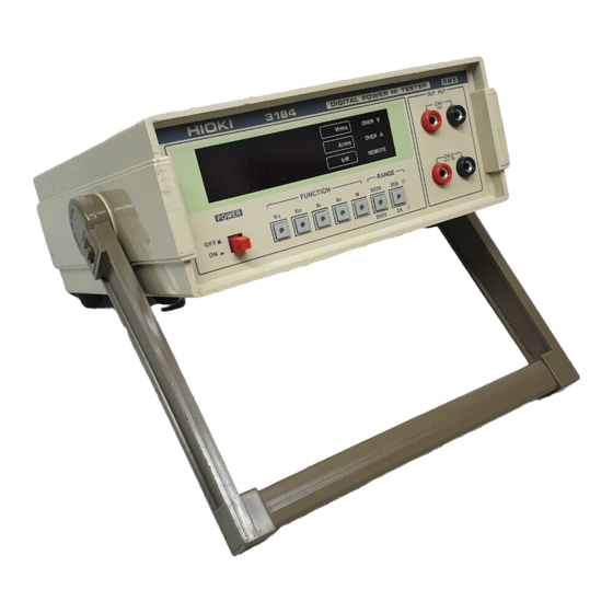
Page 12: Names And Functions Of Parts
――――――――――――――――――――――――――――――――――――――― 1.2 Names and Functions of Parts Front Panel Rear Panel ――――――――――――――――――――――――――――――――――― Chapter 1 Overview... - Page 13 ――――――――――――――――――――――――――――――――――――――― POWER switch Always turn the power switch ON before a measurement. Allow the instrument approximately 5 minutes of warm- Display panel 3-1/2 digits LED display with a maximum display capability of 1999. Measurement unit annunciators are coupled to function switch operation, with the measurement value of V to W, and the unit displayed.
- Page 14 ――――――――――――――――――――――――――――――――――――――― Output Terminals Output is a DC voltage value equivalent to the measurement value (2 VDC/f.s.). CH1: Power only (continually outputs regardless of selected function). CH2: Outputs the value for the displayed function. To avoid damage to the unit, do not short the output CAUTION terminal and do not input voltage to the output terminal.
- Page 15 ――――――――――――――――――――――――――――――――――――――― Measurement Terminal Board The rear panel terminal board is used to connect the device under test with the power source. Connection cables should have sufficient capacity ratings, and be connected securely (and neatly) to avoid accidental short- circuits. Fuse Holder The instrument takes a 0.5 A/250 V arc-quencing, midget type fuse.
- Page 16 ――――――――――――――――――――――――――――――――――――――― Handle ――――――――――――――――――――――――――――――――――― Chapter 1 Overview...
-
Page 17: Chapter 2 Specifications
――――――――――――――――――――――――――――――――――――――― Chapter 2 Specifications 2.1 General Specifications Measurement AC voltage, AC current (true rms), single-and functions 3-phase active (real) power Measurement range 200 V/500 V 2 A/20 A 0.2 kW/2 kW/20 kW Maximum display 199.9 V/500 V value 1.999 A/19.99 A .1999 kW/1.999 kW/19.99 kW Crest factor 2 or less at full-scale... - Page 18 ――――――――――――――――――――――――――――――――――――――― Frequency response within ±1.0% rdg., 40 Hz to 1 kHz (When current input ≦ 18 A, and power-factor = 1.0) within ±1.0% rdg., 45 Hz to 1 kHz (When current input > 18 A, and power-factor = 1.0) Affect of power factor 0.2 kW range within ±1.0% rdg., on accuracy power factor=0.5...
-
Page 19: Chapter 3 Basic Operating Principle
――――――――――――――――――――――――――――――――――――――― Chapter 3 Basic Operating Principle 3.1 Active Power Measurements Low- Auto-zero Amplifier Multiplier pass filter Control Auto-zero Multiplier Panel switch control Amplifier Analog output (CH1) Display Amplifier Selectors converter converter Analog output (CH2) Figure 3.1-1 Circuit Block Diagram A block diagram of the various circuits contained in the 3184 is shown in Figure 3.1-1. -
Page 20: Voltage And Current Measurements
――――――――――――――――――――――――――――――――――――――― The DC component of the calculated waveform is proportional to active power. Output is obtained by extracting this DC component and adjusting it to a 2 VDC/f.s. level. Figure 3.1-2 Figure 3.1-3 Voltage-Current Waveforms Power Conversion Waveform 3.2 Voltage and Current Measurements In conventional measuring instruments, the method of measuring an AC signal is to sense its average value, then make the necessary calculations to convert it to an... -
Page 21: Crest-Factor
――――――――――――――――――――――――――――――――――――――― 3.3 Crest-Factor In measuring instruments, the dynamic range of the meter circuit is expressed as a crest-factor. In measurements where peak-values are high relative to rms value, selecting a suitable range for the rms value will likely result in the waveform peaks exceeding the dynamic range of the signal. Crest-factor is the ratio of peak-value to rms value, defined as follows. - Page 22 ――――――――――――――――――――――――――――――――――――――― Function Range 3184 Voltage 1000 V peak 4 A peak Current 40 A peak If the crest factor in the specification is exceeded, the NOTE displayed data will not be accurate. ――――――――――――――――――――――――――――――――――― Chapter 3 Basic Operating Principle...
-
Page 23: Chapter 4 Operating Instructions
――――――――――――――――――――――――――――――――――――――― Chapter 4 Operating Instructions 4.1 Operating Procedure In order to prevent electric shock and short-circuit WARNING accidents, shut off the power to the line to be measured before connecting the load or power supply to the terminals. In order to maintain safety and assure the stable operating performance of this unit, be sure to connect the ground terminal to a proper ground. - Page 24 ――――――――――――――――――――――――――――――――――――――― ・ Approximately two seconds is required for display to NOTE reach stability after applying input, or selecting function or range. ・ Using the instrument in the presence of magnetic fields (and sometimes meter noise itself) will produce a reading of a few digits even though input is zero.
- Page 25 ――――――――――――――――――――――――――――――――――――――― (6) When voltage or current in the device under test exceeds the measurement range of the instrument that you are using, reduce the level of the input signal using PTs and CTs connected as illustrated in figure 4.1-3. Note however, that PTs and CTs produce phase errors that adversely affect the accuracy of power measurements, and caution is advised when using this setup.
- Page 26 ――――――――――――――――――――――――――――――――――――――― Power Load source Figure 4.1-2 Single-Phase Connection Procedure Power Load source Figure 4.1-3 Connection Procedure Using PTs and CTs ――――――――――――――――――――――――――――――――――― Chapter 4 Operating Instructions...
-
Page 27: Chapter 5 3184-02 Gp-Ib Specifications
――――――――――――――――――――――――――――――――――――――― Chapter 5 3184-02 GP-IB Specifications 5.1 Outline The 3184-02 feature built-in GP-IB interfaces. This allows the instruments to be connected to a GP-IB system for automated measurement data reading, and for program-control of function and range settings. Interface functions also include the ability to transmit a service request in the event of an overvoltage or overcurrent. -
Page 28: Interface Specifications
――――――――――――――――――――――――――――――――――――――― 5.2 Interface Specifications Applicable standard: IEEE 488-1978 Interface functions: All SH functions. All AH functions. Basic talker function, Serial poll function, Unaddress if MLA function. No talk-only mode function. Basic listener function, Unaddress if MTA function No listen-only mode function. All SR functions. -
Page 29: Panel Description
――――――――――――――――――――――――――――――――――――――― 5.3 Panel Description GP-IB status lamps When operated under GP-IB system control, these lamps indicate present device status. Indicates that the device can be controlled externally. Indicates that the device is transmitting a service request to the controller. Indicates that the device is transmitting data as the talker. -
Page 30: Talker Function
――――――――――――――――――――――――――――――――――――――― 5.4 Talker Function Output data format AAA ±DDDDDE±D CR LF (1) (2) (1) Measurement Functions Header Function (Voltage measurement) (Voltage measurement) (Current measurement) (Current measurement) W (Power measurement) Indicates no setting has been made. Overrange (2) Measurement Values Measurement Range Mantissa... -
Page 31: Listener Functions
――――――――――――――――――――――――――――――――――――――― (3) Delimiter "CR" and "LF" are sent as delimiters. An EOI is transmitted simultaneous with "LF". 5.5 Listener Functions Programming code (1) Function Function not set. (2) Range 200 V Voltage range 500 V Current range 20 A (3) Service Request No service request mode. - Page 32 ――――――――――――――――――――――――――――――――――――――― Programming precautions Delimiter Usage When receiving data as the listener, the incoming transmission will be interrupted for internal processing in the following two cases. ・When an "EOI" is received. ・When an "LF" is received. This is disregarded for a "CR". (An unaccompanied "CR" is only effective in breaking the incoming transmission for internal processing when the LACS (Listener Active State) is terminated.)
-
Page 33: Service Requests
――――――――――――――――――――――――――――――――――――――― 5.6 Service Requests When the "S1" mode is set, a service request will be sent in the event of an overvoltage or overcurrent input, or for programming errors such as undefined codes or format errors. Following transmission of the service request, the controller sends a serial poll, and the device responds by transmitting its status byte and resetting the SRQ bit (bit When "S0"... -
Page 34: Usage Precautions
――――――――――――――――――――――――――――――――――――――― 5.7 Usage Precautions (1) Address setting The GP-IB address for the device with this interface is set using the rear panel DIP switch. Any address 0 thru 30 not used by another device in the system can be used. The ON side of the switch represents "1", and the OFF side "0". -
Page 35: Sample Programs
――――――――――――――――――――――――――――――――――――――― (2) Items Regarding Local and Remote Control a. When switching between local and remote control, function and range settings remain the same. b. In the remote status, all panel controls (except the power switch) are ineffective. c. Measurement data is output according to function and range setting, and has no bearing on remote or local status. - Page 36 ――――――――――――――――――――――――――――――――――――――― Program Explanation Defines the data area. Defines the subroutine used when an OVER V/A interrupt occurs. Initializes the power meter. Sets W as function, range for voltage Hi, current Lo, header output, and service request mode. Resets memory used for detecting OVER V/A. Enables interrupt.
- Page 37 ――――――――――――――――――――――――――――――――――――――― (2) With this program, HP-9816 reads voltage, current, and power(single-phase) from the power meter and uses this data to calculate power-factor. Input is taken from V and A 10 CLEAR 701 20 OUTPUT 701;"F1V0A0H0S0" 30 WAIT 2 40 ENTER 701;V 50 ...
- Page 38 ――――――――――――――――――――――――――――――――――――――― ――――――――――――――――――――――――――――――――――― Chapter 5 3184-02 GP-IB Specifications...
-
Page 39: Chapter 6 Maintenance And Service
――――――――――――――――――――――――――――――――――――――― Chapter 6 Maintenance and Service 6.1 Fuse Replacement To avoid electric shock, disconnect the power cord WARNING and the input cord from the connectors before replacing the fuse. Only use fuses of the specified type that is rated for the specified current and voltage. -
Page 40: Service
If the unit is not functioning properly, check the batteries CAUTION and fuse blowing. If a problem is found, contact your dealer or HIOKI representative. Pack the unit carefully so that it will not be damaged during transport, and write a detailed description of the problem. HIOKI cannot bear any responsibility for damage that occurs during shipment.
Need help?
Do you have a question about the HITESTER 3184 and is the answer not in the manual?
Questions and answers