
Related Manuals for Hioki 3470


Summary of Contents for Hioki 3470
- Page 1 Instruction Manual 3470 MAGNETIC FIELD HiTESTER December 2008 Revised edition 4 3470A981-04 08-12H...
-
Page 3: Table Of Contents
Product Overview ..........9 Features ............11 Measurement Example ........13 Names and Functions of Parts ......17 1.4.1 3470 Magnetic Field HiTester ......17 1.4.2 3471 Magnetic Field Sensor ......21 1.4.3 3472 Magnetic Field Sensor ......22 Definition of Measurement Items ...... 23 Screen Configuration and Key Operation Work Flow ............ - Page 4 HOLD or output mode ........70 5 Using Application Software Overview ............73 Installing ............74 5.2.1 Installing the Driver ..........74 5.2.2 Installing software ..........82 Graphic Representation of Measurement Values .............. 85 Transferring Recorded Data to a PC ....88 Configuring the 3470 ........91...
- Page 5 Viewing Version Information ......93 6 Advanced Measurements Outputting Waveform and Resultant RMS Values ............. 95 7 Specifications 3470 Magnetic Field HiTester ......101 7.1.1 Basic Specifications .........101 7.1.2 General Specifications ........103 7.1.3 Application Software ........104 7.1.4 Equations and Functions .........105 3471 Magnetic Field Sensor ......
- Page 6 Contents...
-
Page 7: Introduction
Introduction Introduction Thank you for purchasing the HIOKI “Model 3470 Magnetic Field HiT- ester.” To obtain maximum performance from the instrument, please read this manual first, and keep it handy for future reference. This instruction manual contains instructions for use of the device with the3471 and 3472 Magnetic Field Sensor. -
Page 8: Inspection
When you receive the instrument, inspect it carefully to ensure that no damage occurred during shipping. If damage is evident, or if it fails to operate according to the specifications, contact your dealer or Hioki rep- resentative. 3470-01 Magnetic Field HiTester... - Page 9 Inspection 3470-02 Magnetic Field HiTester 3470 (1) CD (PC application soft- USB cable (1) Instruction man- ware) (1) ual (1) 9445-02 AC Adapter LR6 alkaline battery (4) 9445-03 AC Adapter (EU) 3471 Magnetic Field Sensor (1) 3472 Magnetic Field Sensor (1)
-
Page 10: Safety Information
Safety Information Safety Information This instrument is designed to comply with IEC 61010 Safety Standards, and has been thoroughly tested for safety prior to shipment. However, mishandling during use could result in injury or death, as well as damage to the instrument. Be certain that you understand the instructions and precautions in the manual before use. - Page 11 Safety Information Other Symbols Indicates the location of reference information. (⇒ p. ) Indicates that descriptive information is provided below. Indicates a prohibited action. Measurement Categories (Overvoltage categories) To ensure safe operation of measurement instruments, IEC 61010 establishes safety standards for various electrical environments, catego- rized as CAT I to CAT IV, and called measurement categories.
-
Page 12: Operating Precautions
• Before using the instrument the first time, verify that it operates nor- mally to ensure that the no damage occurred during storage or ship- ping. If you find any damage, contact your dealer or Hioki representative. • Before using the instrument, make sure that the insulation on the cables is undamaged and that no bare conductors are improperly exposed. - Page 13 Never use abra- sives or solvent cleaners. • Hioki shall not be held liable for any problems with a computer system that arises from the use of this CD, or for any problem related to the...
- Page 14 Operating Precautions...
-
Page 15: Overview
1.1 Product Overview Overview 1.1 Product Overview The 3470 Magnetic Field HiTester is designed to measure magnetic flux density and level of magnetic field exposure. • It can be used to assess conformance to ICNIRP 1998 and EN50366 (IEC62233) and in research on magnetic field exposure. - Page 16 5 (P. 73) software use • to set up the 3470 from your PC • to upload data saved on the 3470 to your PC • to monitor RMS values π *1: Available units are T, G, and A/m and the magnetic permeability of air being 4 ×10...
-
Page 17: Features
) and resultant RMS ( ) output can be selected. With a 9759 Output Cable you can connect the 3470 to an oscilloscope or recorder for output of waveforms and resultant RMS values. enables measurement of magnetic field waveforms when... - Page 18 1.2 Features Memory function Records up to 99 measurement data. Function for saving settings Measuring conditions can be stored to enable quick access to the same operating conditions each time you power up. Dual power supply The tester can be powered both by battery and AC power to enable measurements in the field as well as permitting installation for long-term measurements.
-
Page 19: Measurement Example
In this example, r1 = 30 cm. Storage of measurement data : tester memory and PC memory Required equipment : 3470 3471 or 3472 sensor Batteries AC adapter Product whose magnetic field is to be... - Page 20 1.3 Measurement Example Preparations 1. Insert batteries in the tester or connect it to the AC adapter and fold out the stand. Also connect the 3471 or 3472 Magnetic Field Sensors. Insert the sensor in the sensor terminal. Plug the adapter into the AC adapter terminal and the mains plug into an AC wall outlet.
- Page 21 1.3 Measurement Example Setup, measurements and data storage 1. Select Exposure (general public) measurement mode. 2. Select Auto range. ([AUTO] on the display lights.) 3. Place the magnetic field sensor near the DUT. (A distance of 30 cm if the DUT is an electric cooker) Read the indicated value and press to save the measurement data.
- Page 22 1.3 Measurement Example Analysis flow chart START Measurement data ± accuracy < 100% ≥ 100% (Measurement data ± accuracy) × ≤ coupling factor (0 to 1) 100%* ≥ 100% Calculate the induced current Exceeds density with the human body model and a numerical analysis. Evaluation goes below the basic restrictions.
-
Page 23: Names And Functions Of Parts
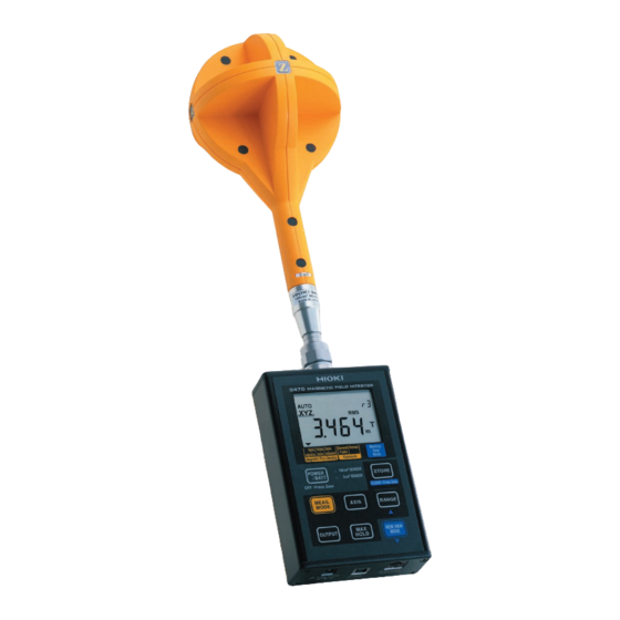
1.4 Names and Functions of Parts 1.4 Names and Functions of Parts 1.4.1 3470 Magnetic Field HiTester Front Sensor terminal Connect the 3471, 3472 Magnetic Field Sensor or a 9758 Extention Cable. 2.2 (P. 32) Display (P. 20) Keys (P. 18) - Page 24 1.4 Names and Functions of Parts keys Keys Description • Turns the power on and off. • Holding down while turning on the power initializes the memory and the saved settings (returning them to their factory defaults). For details on the factory defaults: 4.3 (P. 61) •...
- Page 25 1.4 Names and Functions of Parts Keys Description • Stores measurement data in memory. • Clears displayed measurement data when viewing memory data. 3.7 (P. 52) Switches the displayed axis as shown below: → → → XYZ→ XYZ...(XYZ indicates a resultant value ) *: 1.5 "Definition of Measurement Items"...
- Page 26 1.4 Names and Functions of Parts Note: Icons not described below cannot be used with this tester. Display 1, 2 3, 4 Memory View Mode Displays saved data. 3.7 (P. 52) Magnetic flux density mode Exposure level mode Displays the selected magnetic flux densi- Displays the selected exposure level modes as follows: ty mode.
-
Page 27: 3471 Magnetic Field Sensor
1.4 Names and Functions of Parts 1.4.2 3471 Magnetic Field Sensor Output connector Connects to the 3470 sensor connector. 2.2 (P. 32) Sensor Matching number Use the tester with a sensor that has an identical matching number (up to the hyphen). -
Page 28: 3472 Magnetic Field Sensor
1.4 Names and Functions of Parts 1.4.3 3472 Magnetic Field Sensor x-axis coil Output connector Connects to the 3470 sen- The line indicates the sor connector. x-axis coil. 2.2 (P. 32) Matching number x-axis Sensor Use the tester with a sensor that has an identical matching number (up to the hyphen). -
Page 29: Definition Of Measurement Items
1.5 Definition of Measurement Items 1.5 Definition of Measurement Items Instantaneous values obtained from the x-axis, y-axis and z-axis sensors ) (t ) (t ) (t at time t are referred to as, respectively, while the ˆ t ˆ t ˆ... -
Page 30: Screen Configuration And Key Operation Work Flow
1.6 Screen Configuration and Key Operation Work Flow 1.6 Screen Configuration and Key Operation Work Flow Measurement mode 3.3 (P. 38) Magnetic flux density mode (10 Hz to 400 kHz) indicates selected mode. Magnetic flux density Exposure mode level mode Press Press 3.3 (P. - Page 31 1.6 Screen Configuration and Key Operation Work Flow Screens for verifying and setup Screen name Screen access method Screen displayed Check Battery status Press to view battery status. 3.1 (P. 35), 4.1 (P. 59) Check Saved Data Press in each measure- ment mode.
- Page 32 1.6 Screen Configuration and Key Operation Work Flow Screen name Screen access method Screen displayed Change Unit Indication When the power is off, hold down . And press to turn on [ Unit 4.4.3 (P.66) Set Slow Function When the power is off, hold down .
- Page 33 1.7 Measurement Work Flow 1.7 Measurement Work Flow This section describes measurement work flow. Supplying power 2.1.1 "Connecting the AC Adapter" (P.29) 2.1.2 "Inserting and Replacing Batteries" (P.30) Connect a mag- netic field sensor. 2.2 "Connecting a Magnetic Field Sen- sor"...
- Page 34 1.7 Measurement Work Flow Pre-measurement check 3.2 "Pre-measurement Check" (P.37) Measuring mag- netic fields 3.3 "Measuring Mag- netic Flux Density" (P.38) Transfer the mea- surement data to a PC and use the application soft- ware to analyze the data. 5.3 "Graphic Repre- sentation of Measure- ment Values"...
-
Page 35: Measurement Preparations 29
2.1 Supplying Power Measurement Preparations 2.1 Supplying Power 2.1.1 Connecting the AC Adapter Use only the specified Model 9445-02 AC Adapter (SA110-09S-I, SINO-AMERICAN) AC adapter input voltage range is 100 to 240 VAC (with ±10% stability) at 50/60 Hz. To avoid electrical hazards and damage to the instrument, do not apply voltage outside of this range. -
Page 36: Inserting And Replacing Batteries
2.1 Supplying Power 2.1.2 Inserting and Replacing Batteries • Do not mix old and new batteries, or different types of batteries. Also, be careful to observe battery polarity during installation. Otherwise, poor performance or damage from battery leakage could result. •... - Page 37 2.1 Supplying Power Insert the batteries taking care to match the polarity correctly. Attach the battery compartment lid. Attach Battery compartment lid This completes the battery insertion (replacement) procedure.
-
Page 38: Connecting A Magnetic Field Sensor
Locate the Z-axis of the magnetic field sensor facing forward, insert the output connector of the sensor in the 3470 sensor connector and screw the nut of the sensor in to firmly attach the sensor. -
Page 39: Turning The Power On And Off
2.3 Turning the Power On and Off 2.3 Turning the Power On and Off Turn the power on (off) according to the steps below. Turning on the power Press Turning the power off Hold down for 2 seconds or more. 2 seconds or more... - Page 40 2.3 Turning the Power On and Off...
-
Page 41: Measurement Procedure 35
Before the start of measurements, make the following preparations in the stated order. Press to turn on the power. Make sure that all segments on the LCD display light. After this it will display the model name (3470) and battery sta- tus. - Page 42 3.1 Measurement Preparations Function for checking low battery voltage When battery voltage goes low and lights, the power is forcibly turned off. At this time, also appear. BAtt The magnetic flux density mode screen appears. This ends measurement preparations. • When a setup has been saved (for details refer to 4.2 "Function for Saving Settings (Saving Set Modes and Measurement Ranges)"...
-
Page 43: Pre-Measurement Check
3.2 Pre-measurement Check 3.2 Pre-measurement Check This instrument has been calibrated to operate with the optional sen- sors and should be used only with these sensors. Thus if multiple instruments are used, make sure that each instrument is combined with the correct sensor. Check the following before using the tester. -
Page 44: Measuring Magnetic Flux Density
3.3 Measuring Magnetic Flux Density 3.3 Measuring Magnetic Flux Density Measure magnetic flux density according to the steps below. Press to open the magnetic flux density mode screen. : wide range measurements : power frequency range measurements : extended power frequency range measurements... - Page 45 3.3 Measuring Magnetic Flux Density Press to select measurement range. Range number Ranges are switched in the order shown below. AUTO Range type Range number Range Auto-range Automatically selects appears on the appropriate range dur- display ing measurements. 2 μT/20 mG/1.6 A/m Manual range 20 μT/200 mG/16 A/m 200 μT/2 G/160 A/m...
- Page 46 3.3 Measuring Magnetic Flux Density Place the magnetic field sensor near the DUT. • For accurate measurements, the tester should be located further away from the DUT than the sensor. • Although few magnetic materials are used in the magnetic field tester, the battery is a magnetic material and may affect measure- ments if located close to the DUT.
-
Page 47: Measuring Exposure Level (General Public)
3.4 Measuring Exposure Level (General Public) 3.4 Measuring Exposure Level (General Public) Use this mode to make measurements that conform to EN50366 and IEC62233. 3.4.1 Preparing for Exposure Measurements Use the flow chart below to determine whether to use the slow function setting. - Page 48 3.4 Measuring Exposure Level (General Public) The result of the flow chart assessment is "Turn on the slow function." Use the steps below to open the "QuickSet" screen. (An exposure level (General Public) measurement can be started after turning on the slow function.) When the power is off, hold down and press...
-
Page 49: Exposure Level
3.4 Measuring Exposure Level (General Public) The table below shows the measurement and internal processing times with the slow function on and when it is off. Slow function on Measure- Internal Measure- Internal Measure- Internal Measure- Internal ment processing ment processing ment processing... - Page 50 3.4 Measuring Exposure Level (General Public) • In measuring non-uniform magnetic fields (see figure below) where the sensor may come into contact with a source, it is recommended that measurements be conducted at a distance from the three coils and at an angle (indicated by in the figure below) to maintain isot- ropy of each axis.
-
Page 51: Measurement Procedure
3.4 Measuring Exposure Level (General Public) 3.4.3 Measurement Procedure Measure exposure level (General Public) according to the steps below Press to open the exposure level (General Public) mode screen. - Page 52 3.4 Measuring Exposure Level (General Public) Press to select measurement range. Range number Ranges are switched in the order shown below. AUTO Range type Range number Range Auto-range Automatically selects appears on the appropriate range dur- display ing measurements. Manual range 200% 2000% Range of guaranteed accuracy...
- Page 53 3.4 Measuring Exposure Level (General Public) Place the magnetic field sensor near the DUT. • For accurate measurements, the tester should be located further away from the DUT than the sensor. • Although few magnetic materials are used in the magnetic field tester, the battery is a magnetic material and may affect measure- ments if located close to the DUT.
-
Page 54: Measuring Exposure Level (Occup.)
3.5 Measuring Exposure Level (Occup.) 3.5 Measuring Exposure Level (Occup.) Measuring Exposure Level (Occup.) Press to open the exposure level (Occup.) mode screen. - Page 55 3.5 Measuring Exposure Level (Occup.) Press to select measurement range. Range number Ranges are switched in the order shown below. AUTO Range type Range number Range type Auto-range Automatically selects appears on the appropriate range dur- display ing measurements. Manual range 200% 2000% Range of guaranteed accuracy...
- Page 56 3.5 Measuring Exposure Level (Occup.) Place the magnetic field sensor near the DUT. • For accurate measurements, the tester should be located further away from the DUT than the sensor. • Although few magnetic materials are used in the magnetic field tester, the battery is a magnetic material and may affect measure- ments if located close to the DUT.
-
Page 57: Holding Maximum Value Of The Resultant Rms Values
3.6 Holding Maximum Value of the Resultant RMS Values 3.6 Holding Maximum Value of the Resultant RMS Values This function holds the maximum value of the resultant RMS value R and the values of each axis. 1, 2 Press to hold the maximum value of the resultant RMS and the icon lights. -
Page 58: Checking And Deleting Saved Data
3.7 Checking and Deleting Saved Data 3.7 Checking and Deleting Saved Data 3.7.1 Checking Saved Data Use the following steps to check saved measurement data. You can save up to 99 data. 1, 2 Press to open the screen with the saved data. - Page 59 3.7 Checking and Deleting Saved Data Press ( ) or ( ) to select the memory number of measurement data you wish to check. Memory number Press to return to the measurement mode screen. This completes saving measurement data blinks when measurement data is saved with the slow function...
-
Page 60: Deleting Saved Data
3.7 Checking and Deleting Saved Data 3.7.2 Deleting Saved Data Use the following steps to delete saved measurement data. 1, 2 Press to open the screen with the saved data. - Page 61 3.7 Checking and Deleting Saved Data Press and hold for 2 seconds or more. This deletes the measurement data with the highest memory number. Data can deleted only when moved to the highest memory number. Highest memory number ] appear when data is deleted. dAtA The data for the next highest memory number appears.
- Page 62 3.7 Checking and Deleting Saved Data Press to return to the measurement mode screen. This completes deleting measurement data.
-
Page 63: Deleting All Saved Data
When the power is off, hold down and press This deletes all saved data. ] appear when data is deleted. dAtA Then the model name (3470), battery status and the measure- ment mode screen appear. This completes deleting all saved data. - Page 64 3.7 Checking and Deleting Saved Data...
-
Page 65: Advanced Functions
4.1 Checking Remaining Battery Power Advanced Functions 4.1 Checking Remaining Battery Power Use the procedure below to check remaining battery power. Press The measurement mode screen appears after showing bat- tery status. The screen indicates 100% battery power regardless of battery status when the 9445-02 AC Adapter is connected. -
Page 66: Function For Saving Settings (Saving Set Modes And Measurement Ranges)
4.2 Function for Saving Settings (Saving Set Modes and Measurement Ranges) 4.2 Function for Saving Settings (Saving Set Modes and Measurement Ranges) A frequently used mode can be saved for immediate access. The saved mode appears as soon as the tester is powered up. Follow the steps given below. -
Page 67: Initializing Function (Returning Settings To Their Factory Defaults)
When the power is off, hold down to press ] appears. All clr After this it displays the model name (3470) and battery status, and is restarted using the factory default settings. The factory default settings are listed in the table below. Item... -
Page 68: Other Functions
4.4 Other Functions 4.4 Other Functions The following sections describe other functions that a user should know. 4.4.1 Setting Auto Power Off (Saving Battery Power) • This function saves battery power when the user forgets to turn off the power. •... - Page 69 4.4 Other Functions Press ( ) or ( ) to turn on Press and select [ ] or [ set auto power off. cancel auto power off. Press to save the setting. ] appear and the power is turned off. SAvE...
-
Page 70: Setting Audible Key Feedback
4.4 Other Functions 4.4.2 Setting Audible Key Feedback This function causes the keys to generate a beep when pressed. Follow the steps given below. 1, 4 1, 2 When the power is off, hold down and press Press ( ) or ( ) to turn on [ bEEP... - Page 71 4.4 Other Functions Press and select [ ] or [ audible key feedback is on. audible key feedback is off. Press to save the setting. ] appear and the power is turned off. SAvE...
-
Page 72: Changing Unit Indication
4.4 Other Functions 4.4.3 Changing Unit Indication Use this function to change the unit indication. (The default unit is T.) Follow the steps given below. 1, 4 1, 2 When the power is off, hold down and press Press ( ) or ( ) to turn on [ Unit... - Page 73 4.4 Other Functions Press and select [ ], [ ], or [ T, G, or A/m Press to save the setting. ] appear and the power is turned off. SAvE...
-
Page 74: Setting The Slow Function
4.4 Other Functions 4.4.4 Setting the Slow Function This function performs 1 s sampling and then displays the measurement value. Follow the steps given below. 1, 4 1, 2 When the power is off, hold down and press Press ( ) or ( ) to turn on [ SLou... - Page 75 4.4 Other Functions Press and select [ ] or [ sets the slow function. cancels the slow function. Press to save the setting. ] appear and the power is turned off. SAvE blinks while measuring with the slow function on.
-
Page 76: Turning On The Mem. Mode Key In Max
4.4 Other Functions 4.4.5 Turning on the MEM. MODE key in MAX. HOLD or output mode Use this function to turn on or off the during MAX. HOLD or during output. Checking saved data during output results in output off Follow the steps given below. - Page 77 4.4 Other Functions Press and select [ ] or [ enables in MAX. HOLD mode and output modes. disables in MAX. HOLD mode and output modes. Press to save the setting. ] appear and the power is turned off. SAvE...
- Page 78 4.4 Other Functions...
-
Page 79: Using Application Software
• 10 MB or more free disk space disk capacity • USB Ver. 1.1 or greater Interface • One 3470 unit can be connected at any one time USB hubs with a power consumption exceeding 100 mA must be self- power hubs. CD configuration... -
Page 80: Installing
USB cable will prevent normal completion of the instal- lation procedure. • Only one 3470 tester can be connected to one PC. • You may be informed that a new device has been detected also when a 3470 tester with a different serial number is connected. - Page 81 5.2 Installing Insert the CD according to the instructions that appear to install the driver. Installation procedures for each operating system are provided below. "WindowsXP" (P.75) "Windows2000" (P.76) "WindowsMe" (P.78) "Windows98" (P.79) WindowsXP Insert the supplied CD in the CD-ROM drive. The "...
- Page 82 5.2 Installing Click [ Finish Remove the CD from the CD-ROM drive when the " Found " screen closes. New Hardware Wizard To install further software, go to Section 5.2.2 "Installing software" (P.82) Windows2000 Click [ ] when the " "...
- Page 83 5.2 Installing Select " " and click Search for a suitable driver for my device Next Select " " (deselect other alternatives) and click CD-ROM drives Next Click [ Next...
- Page 84 5.2 Installing Click [ Finish Remove the CD from the CD-ROM drive when the " Found " screen closes. New Hardware Wizard To install further software, go to Section 5.2.2 "Installing software" (P.82) WindowsMe Insert the supplied CD in the CD-ROM drive. The "...
- Page 85 5.2 Installing Click [ Finish Remove the CD from the CD-ROM drive when the " Add New " screen closes. Hardware Wizard To install further software, go to Section 5.2.2 "Installing software" (P.82) Windows98 Click [ ] when the " "...
- Page 86 5.2 Installing Select " " and click Search for the best driver for your device Next Insert the supplied CD in the CD-ROM drive. Select " " (deselect other alternatives) and click CD-ROM drive Next Click [ Next Clicking this button starts file copying.
- Page 87 5.2 Installing Click [ ] in the next screen that appears. Finish Remove the CD from the CD-ROM drive when the " Add New " screen closes. Hardware Wizard To install further software, go to Section 5.2.2 "Installing software" (P.82)
-
Page 88: Installing Software
Insert the CD (PC application software) supplied with the instrument into the CD-ROM drive. Open the folder [ ] included on the CD, then execute English Setup.exe. This will activate the installer and open the "DATA VIEWER for 3470 (EN)" window. Click [ Next... - Page 89 5.2 Installing Click [ ], then specify the installing destination folder. Change Click [ Next Click this button when specify the installing destination. Click [ Install When installation ends, click [ ] in the checking window. Finish Installation is now complete.
- Page 90 ] from the [ ] menu, then Setup Control Panel Start click [ Add/Remove Programs Select " ," then click [ ] or DATA VIEWER for 3470 (EN) Remove Change/Remove Uninstall the program by following the procedure appearing on the screen.
-
Page 91: Graphic Representation Of Measurement Values
(Push the cable plugs all the way in.) USB cable on the 3470 lights and all key operations other than are disabled. • Only one 3470 tester can be connected to a PC at one time. • The effective value logger can obtain up to 32000 data. - Page 92 5.3 Graphic Representation of Measurement Values Click the " " tab in the " Effective Value Logger HIOKI DATA " window to open the " VIEWER for 3470 Effective Value " screen. Logger Menu item Description Fixed Interval Samples at fixed intervals to obtain 20 points per division.
- Page 93 5.3 Graphic Representation of Measurement Values Set sampling method, sampling interval and start measure- ments. Sampling method Sampling interval Click the mouse to move the vertical lines in the graph and to indicate the data for the corresponding time interval at the bot- tom of the screen.
-
Page 94: Transferring Recorded Data To A Pc
5.4 Transferring Recorded Data to a PC Transferring Recorded Data to a PC Use this function to transfer data from the 3470 tester to a PC. The data can be saved in the CSV format on the PC. Turn on the 3470 and select [... - Page 95 " window to open the " " screen. 3470 Entire Read Screen item Description Read Transfers data from the 3470 tester to a Memory Clear Deletes data recorded on the 3470. CSV Save Saves displayed data. File Read Displays saved data.
- Page 96 ] to print the dis- File Read Print played data. Use [ ] to delete recorded data on the 3470 that Memory Clear is no longer needed. Disconnect the USB cable from the tester and the PC and turn off the tester.
-
Page 97: Configuring The 3470
Connect the tester to a PC using the supplied USB cable. (Push the cable plugs all the way in.) USB cable on the 3470 lights and all key operations other than are disabled. Only one 3470 tester can be connected to a PC at one time. - Page 98 Be sure not to change the file extension as this will prevent normal reading of file data. Use [ ] to return the 3470 settings to their fac- Initialize the 3470 tory defaults. Disconnect the USB cable from the tester and the PC and turn...
-
Page 99: Viewing Version Information
(Push the cable plugs all the way in.) USB cable on the 3470 lights and all key operations other than are disabled. Only one 3470 tester can be connected to a PC at one time. Click the " " tab in the " "... - Page 100 5.6 Viewing Version Information Disconnect the USB cable from the tester and the PC and turn off the tester.
-
Page 101: Advanced Measurements
If the ground potential of the device connected to the USB termi- nal differ from that of the device connected to the output terminal, a short circuit current could flow via the 3470 and damage the device connected to the USB terminal by fire. - Page 102 6.1 Outputting Waveform and Resultant RMS Values With a 9759 Output Cable you can connect the 3470 to an oscilloscope or recorder for output of waveforms and resultant RMS values. enables measurement of magnetic field waveforms when Waveform the tester is connected to an oscilloscope or recorder.
- Page 103 6.1 Outputting Waveform and Resultant RMS Values Push the 9759 Output Cable all the way into the 3470 output terminal. 9759 Output Cable Insert the output cable plug in the oscilloscope , recorder, or etc. connector. Press and select a measurement mode.
- Page 104 6.1 Outputting Waveform and Resultant RMS Values Waveform output/ Mode Range No. Range resultant RMS value output 2 μT/20 mG/1.6 A/m Magnetic 100 mV/μT flux density 20 μT/200 mG/16 A/m 10 mV/μT 200 μT/2 G/160 A/m 1 mV/μT 2 mT/20 G/1600 A/m 100 mV/mT Exposure 10 mV/%...
- Page 105 6.1 Outputting Waveform and Resultant RMS Values Each press of the , changes the display as follows: Out- put OFF → Waveform ( lights) → Resultant RMS value lights) → OFF (resultant RMS values are output via the X-axis.) Lights (During resultant RMS value output) This completes output of waveforms and resultant RMS values.
- Page 106 6.1 Outputting Waveform and Resultant RMS Values...
-
Page 107: Specifications
Specifications 7.1 3470 Magnetic Field HiTester This specification applies the 3470 Magnetic Field HiTester tester. The 3471 or 3472 Magnetic Field Sensor is attached to the 3470. 7.1.1 Basic Specifications Measurement accuracy will be maintained when the tester and sensor are used in the environment where the temperature is 23°C±5°C, and... - Page 108 7.1 3470 Magnetic Field HiTester Display update rate approx. 250 ms (slow function off)/ approx. 2 s (slow function on) 4. Measurement Item Measured axes x, y, z Measurement True RMS method Maximum display Measurement Measurement Maximum display value Remarks...
-
Page 109: General Specifications
7.1 3470 Magnetic Field HiTester Prescribed Prescribed accuracy range accuracy range Measurement mode (frequency) (frequency) Magnetic flux density mode 50Hz to 120kHz (10Hz to 400kHz) Magnetic flux density mode 50Hz to 1kHz (10Hz to 2kHz) Magnetic flux density mode 5kHz to 120kHz... -
Page 110: Application Software
7.1 3470 Magnetic Field HiTester Storage tempera- -10°C to 50°C, 80% RH or less (no condensation) ture and humidity Operating tempera- 0°C to 40°C, 80% RH or less (no condensation) ture and humidity Period of guaran- 1 year teed accuracy Power supply Four LR6 alkaline battery 1.5V or 9445-02 AC Adapter (SA110C-09S-I, SINO-... -
Page 111: Equations And Functions
7.1 3470 Magnetic Field HiTester 7.1.4 Equations and Functions Equations Equation Sym- Function Item Continuous Discrete Waveform Instantaneous ) (t output value for each axis at time t ) (t ) (t Resultant value ) (t } { } at time t Δ... - Page 112 7.1 3470 Magnetic Field HiTester Example of characteristics when tester is used with a sensor (magnetic flux density mode) Magnetic flux density mode (10 Hz to 400 kHz) Magnetic flux density Magnetic flux density mode mode (2 kHz to 400 kHz)
-
Page 113: 3471 Magnetic Field Sensor
7.2 3471 Magnetic Field Sensor 7.2 3471 Magnetic Field Sensor Specifications Accuracy at 23°C±5°C, 80% RH or less (no condensation) Sensor cross-sec- 100 cm tional area Rated magnetic 2 mT at a single axis (There is a derating characteristics dependent on fre- flux density quency) Frequency charac-... -
Page 114: 3472 Magnetic Field Sensor
7.3 3472 Magnetic Field Sensor 7.3 3472 Magnetic Field Sensor Specifications Accuracy at 23°C±5°C, 80% RH or less (no condensation) Sensor cross-sec- 3 cm tional area Rated magnetic 2 mT at a single axis (There is a derating characteristics dependent on fre- flux density quency) Frequency... -
Page 115: Maintenance And Service
When sending the instrument for repair, remove the batteries and pack carefully to prevent damage in transit. Include cushioning material so the instrument cannot move within the package. Be sure to include details of the problem. Hioki cannot be responsible for damage that occurs during shipment. -
Page 116: Error Indication
In order to display the version of the 3470, hold down while pow- ering up. The version will be displayed after the model name (3470). 8.4 Cleaning To clean the instrument, wipe it gently with a soft cloth moistened with water or mild detergent. -
Page 117: Appendix
Appendix Appendix 1 ICNIRP Guideline (Basic Restrictions) The exposure levels set for this tester are based on the ICNIRP (Interna- tional Commission on Non-Ionizing Radiation Protection) Guidelines. Basic restrictions apply to current density, SAR and power density. Threshold values have been set on the levels of these physical quanti- ties that affect human health (for example, headaches). -
Page 118: Appendix 2 Coupling Factor In The Icnirp Guidelines
Appendix 2 Coupling Factor in the ICNIRP Guidelines The degree of coupling (coupling factor) of the human body and a mag- netic field changes the effect on the human body. Coupling factor a is 0 ≤ a ≤ 1, where 0 is no coupling and 1 is maximum coupling. -
Page 119: Appendix 3 Graph Showing The Range Of Icnirp 1998 Guidelines
Appendix 3 Graph Showing the Range of ICNIRP 1998 Guidelines The graph below shows the range of the ICNIRP 1998 guidelines. Guideline (ICNIRP1998) range Standard (IEC62233) range [ T ] [ G ] 100m 1000 Occupational level 100μ 10μ 100m General public level 1μ...
Need help?
Do you have a question about the 3470 and is the answer not in the manual?
Questions and answers