Table of Contents
Advertisement
Quick Links
© 2021 TE Connectivity family of companies
All Rights Reserved
*Trademark
TE Connectivity, TE connectivity (logo), and TE (logo) are trademarks. Other logos, product, and/or company names may be trademarks of their respective owners.
DEUTSCH Instructional Manual for
HDP-400 Power Crimper
(TE CONNECTIVITY PN 1606312-1)
SAFETY PRECAUTIONS - AVOID INJURY - READ THIS FIRST! ...................................... 2
1. INTRODUCTION .................................................................................................................. 3
2. SETUP .................................................................................................................................. 5
2.1. AIR SUPPLY SETUP .................................................................................................. 6
2.2. INSTALLING THE LOCATOR ..................................................................................... 8
2.3. INSTALLING THE DIE ................................................................................................ 9
2.4. INSTALLING THE COVER NUT ............................................................................... 10
2.5. CALIBRATING THE DIES ......................................................................................... 11
3. OPERATION AND ADJUSTMENT .................................................................................... 14
4. CALIBRATING THE TOOL ................................................................................................ 14
5. MAINTENANCE ................................................................................................................. 15
6. REPLACEMENT AND REPAIR ......................................................................................... 15
PRODUCT INFORMATION 1-800-522-6752
This controlled document is subject to change.
For latest revision and Regional Customer Service,
visit our website at www.te.com.
Customer Manual
409-35018
17 FEB 21 Rev A
1 of 15
Advertisement
Table of Contents

Related Manuals for TE Connectivity HDP-400


Summary of Contents for TE Connectivity HDP-400
-
Page 1: Table Of Contents
1 of 15 All Rights Reserved For latest revision and Regional Customer Service, *Trademark visit our website at www.te.com. TE Connectivity, TE connectivity (logo), and TE (logo) are trademarks. Other logos, product, and/or company names may be trademarks of their respective owners. -
Page 2: Safety Precautions - Avoid Injury - Read This First
409-35018 SAFETY PRECAUTIONS — AVOID INJURY — READ THIS FIRST! Safeguards are designed into this application equipment to protect operators and maintenance personnel from most hazards during equipment operation. However, certain safety precautions must be taken by the operator and repair personnel to avoid personal injury, as well as damage to the equipment. For best results, application equipment must be operated in a dry, dust-free environment. -
Page 3: Introduction
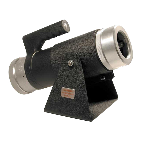
409-35018 Figure 1: HDP-400 power crimper 1 Foot pedal 4 Solenoid/trigger/timer 2 Air fitting (not supplied) 5 Valve 3 Power cord (to 110V or 240V supply) 6 Air exhaust 1. INTRODUCTION When reading this manual, pay particular attention to DANGER, CAUTION, and NOTE statements. - Page 4 The HDP-400 Power Crimp Tool (TE PN 1606312-1) is a precision, pneumatic, full-cycling tool capable of producing four-indent crimps on pin and socket type solid contacts, both HD and CE style, size 20 thru 4. This is accomplished by changing out the die assembly and locators in accordance with factory specifications.
-
Page 5: Setup
409-35018 2. SETUP Each tool is shipped from the factory pre-assembled. The locator and die assembly are not pre-installed. These must be purchased separately and installed by the user. For help in choosing the correct die and locator solution, refer to instruction sheet 408-35142, or contact the factory for assistance. The tool is operated with a foot control pedal (P/N 104), which is an optional purchase. -
Page 6: Air Supply Setup
409-35018 2.1. AIR SUPPLY SETUP The tools is operated with a foot pedal assembly (P/N 104). Use a 1/4" ID, 3/8" OD line capable of 70 to 125 PSI (1-2 CFM). Crimp tool operating pressure is 620 to 861 kPa [90 to 125 PSI] (1-2 CFM). Nominal pressure is 80 PSI. - Page 7 409-35018 The air hose must be connected to the port in the center of the cylinder (Figure 3). Figure 3: Connecting the air hose 7 of 15 Rev A...
-
Page 8: Installing The Locator
409-35018 2.2. INSTALLING THE LOCATOR The function of the locator is to orient the contact in the die housing so that the contact barrel is directly in line with the die indenters. This ensures that the crimp meets the specifications for the particular contact being processed. -
Page 9: Installing The Die
409-35018 2.3. INSTALLING THE DIE To install the crimp die assembly, complete the following steps. NOTE The locator must be installed before you install the die assembly. 1. Find the index pin in the face of the retainer, and the drilled hole in the rear of the die assembly (Figure 5). -
Page 10: Installing The Cover Nut
409-35018 2.4. INSTALLING THE COVER NUT The O-ring (P/N 6230-11) is located on the inside face of the cover nut (Figure 6). During the process of crimping, the contact or terminal grows in length with the displacement of material. The O-ring allows the die set to move forward as the contact is crimped. -
Page 11: Calibrating The Dies
409-35018 2.5. CALIBRATING THE DIES All die sets are marked with the nominal shut height setting (Figure 7). This is the fully closed diameter when the tool is actuated. The dies can be easily checked with NO-GO and GO gages. The tolerance, unless otherwise specified, is plus (+) 0.05 mm [.002 in.] (NO-GO), minus (-) 0.13 mm [.005 in.] (GO). - Page 12 409-35018 To calibrate the dies, complete the following steps. 1. Select the proper NO-GO and GO gage for the die assembly that is in the tool. 2. Depress and hold the gage button on the air inlet side of the tool (Figure 8), which causes the tool to actuate and remain in the closed position.
- Page 13 409-35018 3. Use the gage to check the opening between the indenters (Figure 9) to determine if the die assembly is to the correct dimension. The GO gage should enter freely. A snug fit is acceptable. If the go gage does not enter freely into the die, check to see that you have the correct go/no-go gage.
-
Page 14: Operation And Adjustment
409-35018 3. OPERATION AND ADJUSTMENT 1. Adjust Regulator: With the air supply connected, adjust the regulator to provide approximately 80 lbs PSI. 2. Test Crimp Cycle: Without a contact and wire in place, operate the trigger. Observe the action of the indenters to be sure they operate freely. -
Page 15: Maintenance
5. MAINTENANCE The HDP-400 requires filtered, dry air. The tool is thoroughly lubricated at the factory and if clean, filtered, dry air is provided, it should not require additional lubrication for the first year. The tool is assembled with the highest quality O-ring lubrication, which should provide adequate lubrication under normal conditions for the lifetime of the tool.
Need help?
Do you have a question about the HDP-400 and is the answer not in the manual?
Questions and answers