Table of Contents

Related Manuals for Rohde & Schwarz FSH


Summary of Contents for Rohde & Schwarz FSH
- Page 1 Rohde & Schwarz FSH-Z44 Specs Provided by www.AAATesters.com Test and Measurement Division Quick Start Manual Handheld Spectrum Analyzer R&S FSH 1145.5850.03 1145.5850.13 1145.5850.23 1145.5850.06 1145.5850.26 1145.5850.18 1145.5980.12-12-...
- Page 2 Dear Customer, R&S® is a registered trademark of Rohde & Schwarz GmbH & Co. KG. Trade names are trademarks of the owners. 1145.5980.12-12-...
- Page 3 Safety Instructions This unit has been designed and tested in accordance with the EC Certificate of Conformity and has left the manufacturer’s plant in a condition fully complying with safety standards. To maintain this condition and to ensure safe operation, the user must observe all instructions and warnings given in this operating manual.
- Page 4 1. The unit may be used only in the operating conditions and positions specified by the manufacturer. The R&S FSH is protected against dripping water and dust (IP degree 51). Unless otherwise agreed, the following applies : pollution severity 2, overvoltage category 2, altitude max. 2000 m powered from AC power supply, altitude max.
-
Page 5: Certificate Of Quality
R&S FSH Certificate of quality Certificate of quality Dear Customer, You have decided to buy a Rohde & Schwarz product. You are thus assured of receiving a product that is manufactured using the most modern methods available. This product was developed, manufactured and tested in compliance with our quality management system standards. - Page 6 This is to certify that: Equipment type Stock No. Designation FSH3 1145.5850.03/.13/.23 Handheld Spectrum Analyzer FSH6 1145.5850.06/.26 FSH18 1145.5850.18 FSH-Z1 1155.4505.02 Average Power Sensor FSH-Z2 1145.5767.02 VSWR Bridge and Power Driver FSH-Z3 1300.7756.02 VSWR Bridge FSH-Z14 1120.6001.02 Directional Power Sensor FSH-Z18 1165.1909.02...
-
Page 7: Support Center
R&S FSH Support Center Support Center Should you have any technical questions concerning this Rohde & Schwarz product, please contact the hotline of Rohde & Schwarz Vertriebs-GmbH, Support Center. Our hotline team will answer your questions and find solutions to your problems. -
Page 8: Putting Into Operation
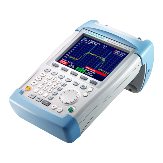
R&S FSH Front view 1 Putting into Operation Front view External trigger/ Connector for external reference power sensor Generator output RF input input BNC connector N connector N connector Connector for Connector for headphones AC power supply Display RS-232-C optical... -
Page 9: Unpacking The Instrument
Section 2 describes the operation of the spectrum analyzer using simple measurements as examples. Unpacking the Instrument The R&S FSH comes in formfitting packaging that consists of upper and lower shells. The two shells are held together by tape. The packaging contains all accessories supplied. -
Page 10: Setting Up The Instrument
To secure the instrument in place, affix its carrying handle to the front of the carrying bag with the Velcro tape. The carrying handle at the top of the R&S FSH can also be used to hang it from cabinet doors, for example. The shape of the grip ensures that the instrument does not fall off. -
Page 11: Switching On The Spectrum Analyzer
R&S FSH displays a connector symbol in the middle of the display above the softkey labels. When the R&S FSH is switched on, it recalls the settings that it was using when it was last switched off. Note: If the internal battery is completely flat, the R&S FSH cannot be switched on even though it is connected to the AC supply via the power supply unit. -
Page 12: Spectrum Analyzer Connectors
If the R&S FSH-Z2 (VSWR bridge up to 3 GHz) or R&S FSH-Z3 (VSWR bridge up to 6 GHz) is used, it is controlled by this connector. - Page 13 Putting into Operation R&S FSH Tracking generator output (models 1145.5850.13, 1145.5850.23 and 1145.5850.26 only) Connect the tracking generator output to the DUT via an N connector. The nominal output level is -20 dBm (100 GW). With the R&S FSH3 model 1145.5850.23, the level can be switched between -20 dBm and 0 dBm (1 mW).
-
Page 14: Screen Settings
When setting the contrast view the display at the same angle that will be used for the application. Confirm the entry with the ENTER key or by pressing the DISPLAY softkey again. The R&S FSH displays the setting in the Display Contrast line in the overview of the setup settings. 1145.5980.12... - Page 15 ENTER key or by pressing the DISPLAY softkey again. In the submenu that opens, select COLOR or BLACK/WHITE. Confirm with the ENTER key or by pressing the DISPLAY softkey again. The R&S FSH switches to the selected color settings. 1145.5980.12 E-12...
-
Page 16: Country-Specific Settings
R&S FSH Putting into Operation Country-Specific Settings The R&S FSH is “multilingual” and can display text in the language of your choice. The softkey lettering is always in English. The default setting (factory-setting) is also English. Selection Press the SETUP key. -
Page 17: Setting The Date And Time
R&S FSH Setting the Date and Time The R&S FSH has an internal clock that can apply a date and time stamp, e.g. for output to a printer or stored data records. The user can reset the date and time. -
Page 18: Charging The Battery
For rapid charging, be sure to switch off the R&S FSH during charging. The charging time is approx. seven hours. If the R&S FSH is switched on, the charging current for the battery is reduced by the current drain of the R&S FSH, which means the battery might not be charged. - Page 19 Confirm the POWER DOWN selection by pressing the ENTER key. The R&S FSH opens a selection window with the settings: 5 minutes, 30 minutes and DISABLE. Using the rotary knob or cursor keys, select the setting you want and confirm by pressing the ENTER key or the GENERAL softkey.
-
Page 20: Selecting The Instrument Default Setup
Press the PRESET key. The R&S FSH is set to the default setup. The span depends on the model. With the R&S FSH3, it is 3 GHz; with the R&S FSH6, 6 GHz, and up to 18 GHz with the R&S FSH18. -
Page 21: External Reference / External Trigger Switchover
R&S FSH External Reference / External Trigger Switchover The Ext Trig/Ext Ref BNC connector on top of the R&S FSH can be used either as an input for an external trigger or an external reference. Switchover is via the SETUP menu. -
Page 22: Using A Preamplifier
If the preamplifier is switched on, its use is coupled to the reference level, thus ensuring the optimum dynamic range of the R&S FSH at all times. The table below shows the positions of the RF attenuator and the preamplifier as a function of the reference level. -
Page 23: Pin Entry
(PIN). When the R&S FSH is delivered, the PIN is set to 0000 and PIN entry is disabled when the R&S FSH is switched on. A PIN, i.e. a four-digit number, can be re-entered whenever you wish. But it is not activated until the PIN mode has been enabled. - Page 24 Using the rotary knob or cursor keys, select PINCODE OFF from the menu and press the ENTER key. Prior to deactivation, the R&S FSH prompts you to enter your PIN. This prevents unauthorized deactivation of PIN protection. Enter your PIN number and confirm with the ENTER key.
-
Page 25: Connecting A Printer
R&S FSH Connecting a Printer The R&S FSH can output a screenshot to a printer equipped with an RS-232-C interface. The optical RS-232-C cable R&S FSH-Z34 is available as an accessory. The Serial/Parallel Converter R&S FSH- Z22 is available as an accessory for printers with a parallel interface. - Page 26 Connecting a Printer Note: The R&S FSH-Z22 is designed for a data transmission rate of max. 38 400 baud (= default setting). Therefore, set the baud rate (PRINTER BAUD RATE) in the SETUP menu to 38 400 baud. The baud rates 9600 baud and 19 200 baud can also be set on the R&S FSH-Z22 by opening its housing.
-
Page 27: Setting The Baud Rate For Remote Control
Setting the Baud Rate for Remote Control R&S FSH Setting the Baud Rate for Remote Control The R&S FSH offers different baud rates for remote control. The desired baud rate is set via the setup menu. Press the SETUP key. -
Page 28: Checking The Installed Options
R&S FSH Checking the Installed Options Checking the Installed Options The R&S FSH displays the installed options in the Setup menu so you can check them: Press the SETUP key. Using the rotary knob or the cursor keys, scroll the status display downwards. -
Page 29: Getting Started
Level -30 dBm Level Measurement First, set the R&S FSH to its default settings to show all the operating steps that are required. Press the PRESET key. The analyzer displays the frequency spectrum from 100 kHz to 3 GHz or 100 kHz to 6 GHz (dependent on the model) –... -
Page 30: Setting The Reference Level
The R&S FSH now displays the generator signal with a higher resolution. The R&S FSH has markers for reading off signal levels and frequencies. Markers are always positioned on the trace. Both the level and frequency at their current positions are displayed on the screen. -
Page 31: Frequency Measurements
The R&S FSH’s trace displays 301 measurement points (associated with 301 frequency or time points along the x axis). The marker is always positioned on one of these measurement points. The R&S FSH calculates the marker frequency from the measurement point frequency, and the center frequency and frequency span that have been set. -
Page 32: Harmonic Measurements Of A Sinewave Signal
Enter '250' using the numeric keypad and confirm the entry with the MHz key. The R&S FSH now displays the spectrum from 50 MHz to 250 MHz and thus the signal at 100 MHz and its second harmonic at 200 MHz. -
Page 33: Power Measurements Using The Power Sensor
Power Measurements Using the Power Sensor For highly accurate power measurements, the R&S FSH provides the Power Sensor R&S FSH-Z1 or R&S FSH-Z18 as options. They measure power in the span 10 MHz to 8 GHz or 10 MHz to 18 GHz, respectively. - Page 34 "Power Sensor Zero OK" and switches back to the softkey menu for the power sensor. Connect the signal under test to the R&S FSH-Z1 or R&S FSH-Z18. The R&S FSH shows the measured power level in dBm. For a highly accurate measurement, enter the frequency of the signal under test.
- Page 35 They are driven and powered via a special serial interface. The cable on the power sensor must be connected and screw-fastened to the power sensor connector on the R&S FSH. The directional power sensor itself has to be inserted between the source and the load.
- Page 36 Measurements on CW Signals R&S FSH The R&S FSH opens the screen and the menu for the power measurement. If no power sensor is connected, no measured value is displayed. If a power sensor is connected, the R&S FSH establishes a connection to the power sensor via the interface and, after a few seconds, displays the connected power sensor type (R&S FSH-Z14 or R&S FSH-Z44) as well as the measured forward power and return...
-
Page 37: Two Port Transmission Measurements
ENTER key or the MEAS softkey. The R&S FSH switches on the tracking generator and calls up its softkey menu. When the tracking generator is switched on, the R&S FSH displays Track Gen Uncal . This indicates that tracking generator measurements are uncalibrated. - Page 38 If the reference is changed after calibration, greater measurement uncertainty must be anticipated (up to 1 dB). The R&S FSH retains the calibration data but displays a red dot in front of •Transmission . When saving a data set for a scalar transmission measurement in a calibrated state, the R&S FSH can store the calibration data along with the other settings (see section "Saving Calibration Data").
-
Page 39: Measurement Of Return Loss
(Only for R&S FSH with tracking generator: order no. 1145.5850.13, 1145.5850.23 or 1145.5850.26.) For reflection measurements, the VSWR Bridge R&S FSH-Z2 (up to 3 GHz) or R&S FSH-Z3 (up to 6 GHz) and a short standard (supplied with the bridge) are needed. The VSWR bridge is screw- connected to the RF input connector and the generator’s output. - Page 40 Alternately, the start and stop frequency can be input using the START and STOP softkeys in the frequency menu. Calibrate the R&S FSH for the return loss measurement. The following example shows a scalar measurement of return loss. If the option R&S FSH-K2 is installed, measurement must first be switched to scalar. Press the MEAS key.
- Page 41 5 °C from its temperature when the data set was stored. If the temperature deviation is greater, the R&S FSH outputs a (red) dot in front of • Reflection . A precise measurement can then be made only after a calibration.
-
Page 42: Performing Distance To Fault Measurements
ENTER key or the MEAS softkey. The R&S FSH switches on the distance-to-fault measurement function. The R&S FSH delivers optimum results if the center frequency is set to the frequency at which the device under test is operated. Press the FREQ key. - Page 43 Entering the cable parameters at a specific frequency If cables are used that are not listed in cable models stored in the R&S FSH, it is possible to enter the cable parameters at a specific frequency. It is advisable to use the center frequency of the DTF measurement.
- Page 44 The R&S FSH uses the cable length to determine the optimal span for the measurement and for scaling the x axis in DTF mode. For best results, the cable should be specified 20% to 50% longer than the actual cable length.
- Page 45 5°C. If the temperature deviates more than this amount, the R&S FSH shows a red dot in front of the • DTF display . A new calibration is then necessary.
- Page 46 (step = 10 % of the span). For higher fault resolution, the R&S FSH offers a zoom function in the position of the marker. The x axis of the display can be extended up to a span of 3 m.
- Page 47 The R&S FSH turns off the tracking generator and displays the spectrum over the span of the DTF measurement. To indicate that the R&S FSH is in the spectrum mode, DTF Spectrum is displayed in the upper right-hand corner of the screen. Otherwise, the R&S FSH uses exactly the same settings as it did for DTF measurements.
-
Page 48: Operation In Receiver Mode
(Available only if the option R&S FSH-K3 is installed.) To provide a means of measuring levels at a specific frequency, the R&S FSH offers the receiver mode as an option (option R&S FSH-K3). With this option, the R&S FSH functions like a receiver that measures the level at a predefined frequency. - Page 49 Tuning the frequency in channel grids As an alternative to entering the frequency, the R&S FSH can also be tuned in channels. The channel tables that the R&S FSH uses to set channel frequencies are defined either by using the R&S FSH View software or by directly entering the first channel number, the associated frequency, the number of channels and the channel spacing.
- Page 50 Enter the frequency spacing for the channels and confirm with the ENTER key. Press the EXIT key to exit the menu for defining channel tables. The R&S FSH will now show channel numbers rather than the frequency. It also shows the associated frequency above Channel.
- Page 51 Using the rotary knob or cursor keys, change the bandwidth and confirm with the ENTER key, or, using the numeric keypad, manually enter bandwidth and confirm by pressing the units key. According to CISPR16 the bandwidth is connected to the frequency. The R&S FSH allows to couple the bandwidth to the set frequency automatically: Press the softkey AUTO CISPPR BW.
- Page 52 R&S FSH Scanning in the receiver mode In the receiver mode, the R&S FSH can scan across a defined number of frequencies and graphically display the results. It performs a measurement at each frequency for the defined measurement time. Press the SPAN softkey.
- Page 53 For easy operation, device setup can be performed in accordance with a standard. The standard settings are defined by means of the supplied R&S FSH VIEW PC software in the standard editor. Determining the carrier power (reference) The reference is determined by measuring power/level in the reference channel.
-
Page 54: Determining The Reference
Before the carrier-to-noise power ratio can be determined, the reference power or the reference level must be defined. The R&S FSH measures the reference in accordance with the standard that has been set. Alternatively, the reference can be set manually. - Page 55 Using the rotary knob or the cursor keys, select LEVEL ADJUST and confirm your choice with the ENTER key or the LEVEL softkey. The R&S FSH is adjusted to the optimum level on the basis of the input signal. 1145.5980.12 2.27...
- Page 56 The results plotted on the trace are then integrated to form the total power. The R&S FSH takes into account the behavior of the selected display mode (linear or logarithmic) of the selected detector and the resolution bandwidth. The narrow resolution bandwidth acts like a steep channel filter, thus preventing out-of-channel emissions from affecting the result.
- Page 57 ENTER key or the CHANNEL BW softkey. Enter the desired value and terminate the entry with the appropriate unit key. The R&S FSH automatically adjusts the frequency span in the Auto Span setting to the entered noise channel measurement bandwidth.
- Page 58 Correcting the displayed average noise level The R&S FSH permits a correction of the C/N result by the displayed average noise level of the R&S FSH. The value of the displayed average noise level (receiver noise figure) depends on the device setup dynamic range, preamplifier, and reference level.
-
Page 59: Saving And Recalling Settings And Test Results
By pressing the BACK key, you can instruct the R&S FSH to browse through the list of names of the data sets already stored and display them with the first available free extension. Thus, the name of the data set recalled for a specific measurement can be selected for storing the measurement data. - Page 60 Saving and Recalling Settings and Test Results R&S FSH Use the key to move the cursor to the left. Use the key to move the cursor to the right. Insert a new letter or number at the cursor position using the alphanumeric keypad.
-
Page 61: Saving Calibration Data
If it deviates more than 5°C, the R&S FSH displays a red dot in front of the • Transmission or • Reflection display. Recalibration is then necessary. -
Page 62: Recalling Measurement Results
Press the SCREEN -> PRINTER softkey to send the displayed data set to a printer. Pressing the ACTIVATE softkey transfers the stored trace to the R&S FSH's trace memory. The current trace can be compared with the stored one by switching on the trace memory. -
Page 63: Printing Out Measurement Results
Printing Out Measurement Results The R&S FSH can send screenshots to a printer equipped with a serial interface. The type of printer and the baud rate of the serial interface can be defined in the setup menu (SETUP key) by using the GENERAL softkey and selecting 'PRINTER BAUD...' and 'PRINTER TYPE...' from the menu.
Need help?
Do you have a question about the FSH and is the answer not in the manual?
Questions and answers