Sign In
Upload
Manuals
Brands
Rohde & Schwarz Manuals
Measuring Instruments
FSH4
Rohde & Schwarz FSH4 Handheld Analyzer Manuals
Manuals and User Guides for Rohde & Schwarz FSH4 Handheld Analyzer. We have
5
Rohde & Schwarz FSH4 Handheld Analyzer manuals available for free PDF download: Operating Manual, Quick Start Manual, How To Perform
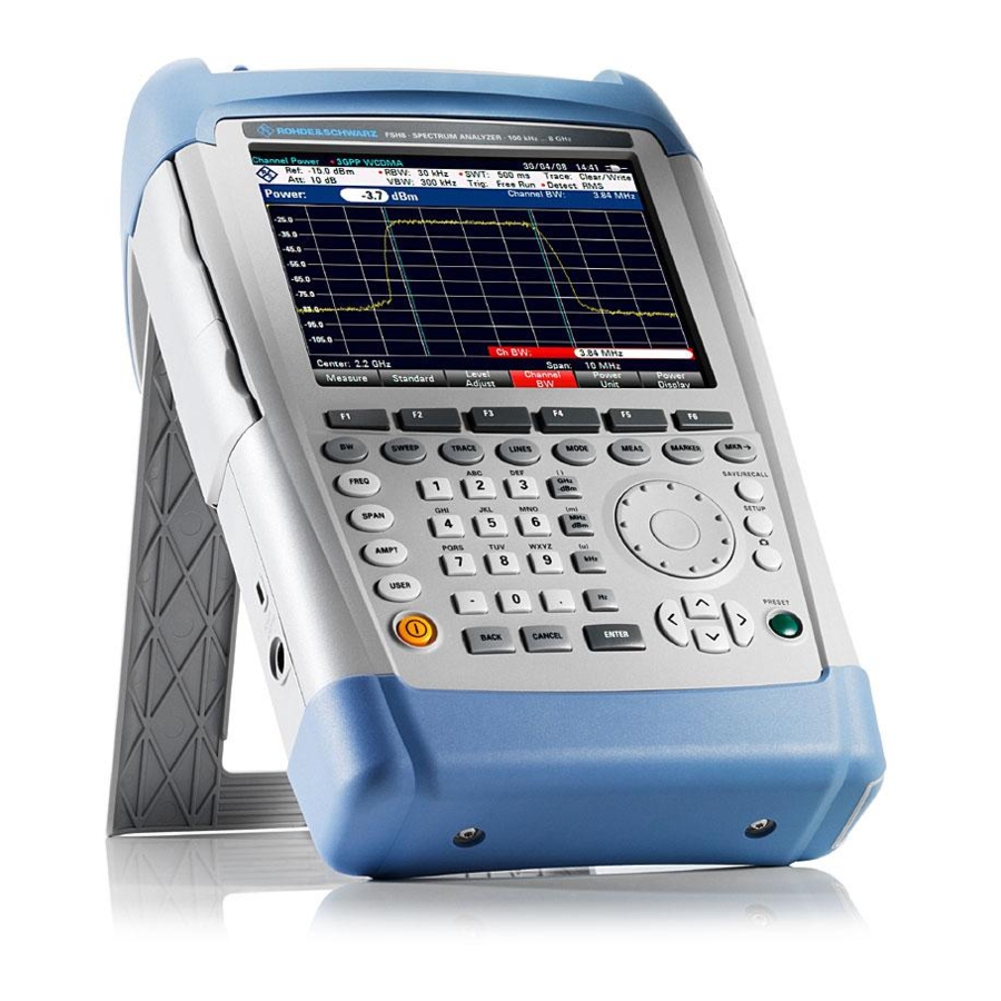
Rohde & Schwarz FSH4 Operating Manual (380 pages)
Spectrum Analyzer
Brand:
Rohde & Schwarz
| Category:
Measuring Instruments
| Size: 8.18 MB
Table of Contents
Operating Manual
1
Basic Safety Instructions
3
Table of Contents
16
Documentation Overview
24
Conventions Used in the Documentation
25
1 Operating the R&S FSH
26
Screen Layout and Elements
26
Means of Input
27
Using the Alphanumeric Keys
28
Confirming and Cancelling Entries
29
Using the Rotary Knob
29
Remote Operation
30
Configuring Measurements
31
Presetting the R&S FSH
31
Configuring the Instrument
32
Taking Screenshots
35
Saving Events
36
Connecting the R&S FSH to a PC
38
Using the Cursor Keys
30
Connecting the R&S FSH in a LAN
39
Connecting the R&S FSH in an Existing LAN
42
Connecting the R&S FSH Via USB
43
Managing Datasets
44
Saving Datasets
46
Restoring Datasets
51
Deleting Datasets
53
Installing Firmware Options
54
Updating the Firmware
54
2 Working with the Measurement Wizard
55
Creating a Measurement Set
56
Preparing the Measurement
56
Uploading Measurement Sets
58
Starting the Measurement Wizard
59
Using the Measurement Wizard
59
Performing a Sequence of Measurements
61
Evaluating Results
64
Measuring Basic Signal Characteristics
65
Measuring the Channel Power of Continuously Modulated Signals
66
Measuring the Occupied Bandwidth
70
Power Measurements on TDMA Signals
74
Measuring the Adjacent Channel Leakage Ratio (ACLR)
77
Measuring the Spectrum Emission Mask
86
Measuring the Harmonic Distortion
89
Measuring the am Modulation Depth
91
Measuring Spurious Emissions
93
3 Spectrum Analyzer Mode
65
Performing Spectrum Measurements
65
Working with the Spectrogram Result Display (R&S FSH-K14/ -K15)
96
Using Isotropic Antennas
107
Configuring Spectrum Measurements
109
Configuring the Horizontal Axis
109
Configuring the Vertical Axis
113
Setting Bandwidths
117
Configuring and Triggering the Sweep
120
Working with Traces
126
Using Markers
131
Using Display Lines
140
Using Limit Lines
141
Working with Channel Tables
144
Using Transducer Factors
145
Setting the Reference Level
146
Unit for Measurements with Transducers
146
Data Sets Containing Transducer Factors
147
Frequency Range of Transducer
147
4 Power Meter
148
Using a Power Sensor
148
Connecting a Power Sensor
150
Performing and Configuring Measurements
151
Using a Directional Power Sensor
154
Connecting a Directional Power Sensor
155
Performing and Configuring Measurements
156
Using the Internal Power Meter
159
Performing Pulse Power Measurements (R&S FSH-K29)
160
Configuring the Numerical Result Display
163
Configuring the Power Vs Time Result Display
163
5 Interference Analyzer (R&S FSH-K15/ -K16)
167
Measuring the Carrier-To-Noise Ratio
169
Measuring the Spectrum
169
Measuring the Carrier-To-Interference Ratio
170
Analyzing Interference Measurements
171
Working with Maps
172
Transferring Maps (R&S FSH-K15 and -K16)
172
Transferring Indoor Maps (R&S FSH-K17)
173
Displaying Maps
174
Measuring Interference
180
Collecting Geographic Data (R&S FSH-K15 and -K16)
183
Collecting Measurement Data (R&S FSH-K17)
187
Analyzing Geographic Data (R&S FSH-K15 and -K16)
190
Analyzing Indoor Data (R&S FSH-K17)
191
6 Network Analyzer Mode
192
Configuring the Tracking Generator
194
Calibrating Measurements
196
Measuring the Transmission
202
Performing Scalar Measurements
202
Measuring the Reflection
204
Performing Vector Measurements (R&S FSH-K42)
206
Measuring the Transmission
207
Measuring the Reflection
210
Evaluating the Results
212
Selecting the Measurement Format
212
Configuring the Vertical Axis
220
Using Limit Lines
223
Using Markers
223
Using Trace Mathematics
223
Vector Voltmeter (R&S FSH-K45)
224
Working with Channel Tables
223
Calibrating Measurements
225
Performing Measurements
226
Evaluating the Results
228
7 Distance-To-Fault Mode (R&S FSH-K41)
229
Performing Cable and Antenna Measurements
231
Reflection Measurements
231
Distance to Fault Measurements
232
Spectrum Measurements
232
Selecting the Measurement Format
233
Calibrating Measurements
235
Configuring Cable and Antenna Tests
236
Selecting the Cable Model
236
Configuring the Horizontal Axis
239
Configuring the Amplitude Characteristics
241
Configuring the Tracking Generator
243
Analyzing Measurement Results
244
Working with Traces
244
Using Display and Limit Lines
245
8 Receiver Mode (R&S FSH-K43)
246
Using Markers
245
Performing Single Frequency Measurements
247
Selecting the Measurement Mode
247
Performing Frequency Scans
250
Configuring Measurements in Receiver Mode
253
Selecting Detectors for EMI Measurements
253
Selecting the Measurement Bandwidths for EMI Measurements
255
Defining the Measurement Time
256
Using Limit Lines
257
9 Digital Modulation Analyzer
258
Using Transducers
257
Working with Traces
257
General Settings in the Result Summary
259
General Settings of the Digital Modulation Analyzer
259
Trace Mode Selection
262
General Result Displays of the Digital Modulation Analyzer
264
Measurements on GSM Signals
267
The Result Summary
268
The Burst Power Result Display
272
Configuring the Measurement
274
Measurements on 3GPP FDD Signals
275
The Result Summary
276
The Code Domain Analyzer
280
The Code Domain Channel Table
282
Configuring the Measurement
284
Measurements on CDMA2000 Signals
288
The Result Summary
289
The Code Domain Analyzer
292
The Code Domain Channel Table
294
The PN Scanner
296
Configuring the Measurement
297
Measurements on 1Xev-DO Signals
300
The Result Summary
301
The PN Scanner
304
The Burst Power Result Display
305
Configuring the Measurement
306
Measurements on TD-SCDMA Signals
307
The Result Summary
308
The Code Domain Analyzer
312
The Code Domain Channel Table
314
The Sync ID Result Display
316
The Time Domain Power Result Display
317
Configuring the Measurement
319
Measurements on LTE Signals
323
The Result Summary
324
The Result Summary for Carrier Aggregation
330
The Constellation Diagram
331
The BTS Scanner
333
The Resource Allocations Result Display
334
Configuring the Measurement
336
10 Menu and Softkey Overview
342
General Functions
342
General R&S FSH Setup
342
File Management
343
Operating Mode Selection
343
Functions of the Spectrum Analyzer
344
Measurement Selection
344
Frequency Parameters
346
Amplitude Parameters
347
Bandwidth Selection
347
Span Selection
347
Sweep Configuration
347
Display and Limit Lines
348
Markers
348
Functions of the Network Analyzer
350
Trace Functionality
348
Frequency Parameters
350
Measurement Configuration
350
Amplitude Parameters
351
Bandwidth Selection
351
Span Selection
351
Sweep Configuration
351
Limit Lines
352
Markers
352
Functions of the Power Meter
354
Trace Functionality
352
Frequency Parameters
354
Power Meter Measurements
354
Amplitude Parameters
355
Bandwidth Configuration
355
Sweep Configuration
355
Trace Configuration
356
Functions of the Distance-To-Fault Mode
357
Frequency Parameters
357
Measurement Configuration
357
Amplitude Parameters
358
Bandwidth Selection
358
Span Selection
358
Sweep Configuration
358
Markers
359
Functions of the Receiver Mode
360
Trace Functionality
359
Frequency Parameters
360
Measurement Configuration
360
Span Selection
360
Amplitude Parameters
361
Bandwidth Selection
361
Sweep Configuration
361
Trace Functionality
361
Markers
362
Functions of the Interference Analyzer (Map Mode)
363
Frequency Parameters
363
Measurement Configuration
363
Amplitude Parameters
364
Bandwidth Selection
364
Sweep Configuration
364
Trace Functionality
364
Functions of the Digital Modulation Analyzer
365
Measurement Configuration
365
Frequency Parameters
367
Amplitude Parameters
368
Sweep Configuration
368
Trace Functionality
369
11 How a Spectrum Analyzer Works
370
Index
376
Advertisement
Rohde & Schwarz FSH4 Operating Manual (250 pages)
Spectrum Analyzer
Brand:
Rohde & Schwarz
| Category:
Measuring Instruments
| Size: 8.87 MB
Table of Contents
Table of Contents
20
Operating the R&S FSH
32
Screen Layout and Elements
32
Means of Input
33
Using the Alphanumeric Keys
33
Confirming and Cancelling Entries
34
Using the Rotary Knob
34
Using the Cursor Keys
35
Presetting the R&S FSH
35
Taking Screenshots
36
Measurement Setup
36
Instrument Setup
37
Updating the Firmware
39
Installing Firmware Options
39
Menu and Softkey Overview
40
General Functions
40
General R&S FSH Setup
40
File Management
41
Operating Mode Selection
41
Functions of the Spectrum Analyzer
42
Measurement Selection
42
Frequency Parameters
44
Span Selection
44
Amplitude Parameters
45
Sweep Configuration
45
Bandwidth Selection
45
Trace Functionality
46
Display and Limit Lines
46
Markers
46
Functions of the Network Analyzer
47
Measurement Configuration
47
Frequency Parameters
48
Span Selection
48
Amplitude Parameters
48
Sweep Configuration
48
Bandwidth Selection
49
Trace Functionality
49
Limit Lines
49
Markers
50
Functions of the Receiver Mode
51
Measurement Configuration
51
Frequency Parameters
51
Amplitude Parameters
51
Span Selection
52
Sweep Configuration
52
Bandwidth Selection
52
Trace Functionality
52
Markers
52
Functions of the Power Meter
53
Power Meter Measurements
53
Frequency Parameters
53
Amplitude Parameters
54
Sweep Configuration
54
Functions of the Distance-To-Fault Mode
54
Measurement Configuration
54
Frequency Parameters
55
Span Selection
55
Amplitude Parameters
55
Sweep Configuration
55
Bandwidth Selection
56
Trace Functionality
56
Markers
56
Functions of the Digital Modulation Analyzer
57
Measurement Configuration
57
Frequency Parameters
59
Amplitude Parameters
59
Sweep Configuration
59
Trace Functionality
60
Spectrum Analyzer Mode
61
Performing Spectrum Measurements
61
Measuring the Channel Power of Continuously Modulated Signals
61
Selecting the Standard
62
Setting the Reference Level
63
Setting the Channel Bandwidth
63
Changing the Span
63
Measuring the Maximum Channel Power
64
Unit for Power Display
64
Measuring the Occupied Bandwidth
65
Selecting a Standard
66
Setting the Reference Level
66
Setting the Channel Bandwidth
67
Defining the Percentage of Occupied Bandwidth
67
Changing the Span
68
Power Measurements on TDMA Signals
68
Selecting a Standard
69
Setting the Burst Length
70
Setting the Reference Level
70
Using a Trigger
70
Measuring the Adjacent Channel Leakage Ratio (ACLR)
71
Selecting a Standard
74
Configuring the Measurement
75
Normalization of Measurement Results
77
Displaying Absolute and Relative Results
77
Selecting the Reference Channel
78
Setting and Checking the Limits
78
Measuring the Spectrum Emission Mask
79
Selecting a Standard
80
Optimizing Measurement Settings
81
Viewing the Results in a Table
81
Measuring the Harmonic Distortion
82
Defining the Number of Harmonics
83
Optimizing the Display of Harmonics
84
Activating the Harmonics List
84
Measuring the am Modulation Depth
84
Setting a Threshold
85
Optimizing the Settings
85
Activating the Marker List
86
Working with the Spectrogram Result Display (R&S FSH-K14)
86
Controlling the Spectrogram Update
87
Browsing through the Signal History
88
Configuring the Display
89
Recording a Spectrogram
91
Playback of a Spectrogram
92
Using Isotropic Antennas
94
Configuring Spectrum Measurements
96
Configuring the Horizontal Axis
96
Defining the Center Frequency
96
Defining a Frequency Step Size
97
Setting a Frequency Offset
97
Defining a Start and Stop Frequency
98
Setting the Span
98
Configuring the Vertical Axis
99
Setting the Reference Level
99
Setting a Display Range
100
Selecting the Display Unit
100
Setting a Reference Offset
101
Setting the RF Attenuation
101
Using the Preamplifier
102
Setting the Input Impedance
103
Using Transducer Factors
103
Setting Bandwidths
103
Setting the Resolution Bandwidth
103
Setting the Video Bandwidth
105
Configuring and Triggering the Sweep
106
Setting the Sweep Time
106
Selecting the Sweep Mode
107
Working with Trigger Functionality
107
Working with Traces
110
Selecting the Trace Mode
110
Selecting the Detector
112
Working with a Second Trace
114
Working with Memory Traces
114
Using Trace Mathematics
115
Using Markers
115
Positioning Markers
116
Positioning a Delta Marker
117
Selecting the Marker Type
118
Automatic Positioning of Markers
118
Removing Markers
118
Using Marker Search Limits
119
Using Marker Functions
120
Using Display Lines
124
Using Limit Lines
124
Selecting a Limit Line
125
Performing Limit Checks
126
Working with Channel Tables
127
Using Transducer Factors
128
Unit for Measurements with Transducers
129
Setting the Reference Level
129
Frequency Range of Transducer
130
Data Sets Containing Transducer Factors
130
Using a Power Sensor
131
Working with Power Sensors
131
Connecting a Power Sensor
132
Performing and Configuring Measurements
133
Using a Directional Power Sensor
136
Connecting a Directional Power Sensor
137
Performing and Configuring Measurements
137
Network Analyzer Mode
141
Calibrating Measurements
142
Calibration States
143
Calibration Methods
144
Performing Calibration
146
Performing Scalar Measurements
148
Measuring the Transmission
148
Measuring the Reflection
150
Performing Vector Measurements (R&S FSH-K42)
151
Measuring the Transmission
152
Measuring the Reflection
153
Evaluating the Results
155
Selecting the Measurement Format
155
Working with the Smith Chart
157
Working with the Dual Trace Mode
160
Configuring the Vertical Axis
161
Using Limit Lines
164
Using Markers
164
Using Trace Mathematics
164
Working with Channel Tables
164
Vector Voltmeter (R&S FSH-K45)
165
Calibrating Measurements
166
Performing Measurements
166
Performing Reflection Measurements
167
Evaluating the Results
168
Performing Transmission Measurements
167
Comparing Results
168
Configuring the Vertical Axis
168
Distance-To-Fault Mode (R&S FSH-K41)
169
Performing Cable and Antenna Measurements
171
Reflection Measurements
171
Distance to Fault Measurements
172
Selecting the Measurement Format
173
Spectrum Measurements
173
Calibrating Measurements
174
Selecting the Measurement Format
168
Calibration Methods
174
Calibration States
174
Performing a Full 2-Port Calibration
174
Configuring Cable and Antenna Tests
174
Selecting the Cable Model
174
Creating a Cable Model
175
Selecting a Predefined Cable Model
175
Working with a DTF List
176
Configuring the Horizontal Axis
177
Setting the Frequency Range for DTF Measurements
177
Selecting the Cable Length
178
Configuring the Vertical Axis
179
Adjusting the Scale of the Diagram
179
Setting the Attenuation
180
Using Display and Limit Lines
181
Using Markers
181
Performing Single Frequency Measurements
182
Receiver Mode
182
Selecting the Measurement Mode
182
Defining the Receive Frequency
183
Customizing the Bargraph Aspects
184
Performing Frequency Scans
185
Defining the Scan Range
186
Using Markers
187
Configuring Measurements in Receiver Mode
187
Selecting Detectors for EMI Measurements
187
Selecting the Measurement Bandwidths for EMI Measurements
188
Defining the Measurement Time
189
Using Transducers
189
Digital Modulation Analyzer
190
Measurements on 3GPP FDD Signals
195
The Result Summary
195
General Settings
196
Global Results
197
Channel Results
198
The Code Domain Analyzer
199
Diagram Header
200
Header Table
200
Diagram Area
201
The Code Domain Channel Table
201
Channel Table
202
Configuring the Measurement
203
Global Results
202
Header Table
202
Specifying the Scrambling Code
203
Selecting the Slot and Code Channel
204
Setting the Antenna Diversity
204
Changing the Code Power
205
Performing Fast Measurements
205
Measurements on CDMA2000 Signals
206
The Result Summary
206
General Settings
207
Global Results
208
Channel Results
209
The Code Domain Analyzer
209
Diagram Area
210
The Code Domain Channel Table
211
Header Table and Diagram Header
210
Channel Table
211
The PN Scanner
212
Configuring the Measurement
213
Global Results
211
Header Table
211
Changing the Code Order
213
Setting the Base Spreading Factor
213
Changing the Reference Power
214
Selecting the Unit of the Carrier Frequency Error
214
Changing the PN Offset
215
Synchronizing to a Base Station Using a GPS Receiver
215
Measurements on 1Xev-DO Signals
215
The Result Summary
216
General Settings
216
Global Results
217
Channel Results
218
The PN Scanner
218
Configuring the Measurement
219
The Burst Power Result Display
219
Changing the PN Offset
219
Selecting the Unit of the Carrier Frequency Error
219
Synchronizing to a Base Station Using a GPS Receiver
220
Measurements on LTE Signals
220
The Result Summary
221
General Settings
221
Global Results
222
Allocation Summary
223
Reference Signal Overview
224
The Constellation Diagram
224
The Resource Allocations Result Display
226
Configuring the Measurement
227
Selecting the Channel Bandwidth
227
Selecting the Cell Identity
228
Selecting the Cyclic Prefix
228
Selecting the MIMO Configuration
229
Selecting the Subframe Configuration for TDD Signals
229
Selecting the Synchronization Signal
229
Configuring EVM Results
230
Saving and Loading Instrument Settings and Measurement Results
232
Saving Data Sets
232
Putting Together a File Name
234
Quick Naming of Data Sets
234
Designing a Table
235
Loading Measurement Results
235
Loading a Dataset
236
Previewing a Dataset
236
Quick Recall of Instrument Settings
236
Compiling a Measurement Report
237
Deleting Datasets
238
How a Spectrum Analyzer Works
240
Selecting the Unit of the Carrier Frequency Error
230
Rohde & Schwarz FSH4 Operating Manual (142 pages)
Handheld Spectrum Analyzer
Brand:
Rohde & Schwarz
| Category:
Measuring Instruments
| Size: 5.44 MB
Table of Contents
Operating Manual
3
Table of Contents
5
1 Putting into Operation
30
2 Getting Started
31
3 Operation
32
Screen Layout
32
Screen Layout for Spectrum-Mode Measurements Without Markers
32
Screen Layout When the Marker Mode Is Selected
33
Entering Measurement Parameters
34
Entering Values and Texts
34
Entering Units
35
Tables
36
Menu Overview
36
General Settings
37
Selection of the Measurement Mode
37
Softkeys of the Spectrum Analyzer Mode
38
Bandwidth Settings
38
Frequency Entry
38
Frequency Span
38
Level Settings
38
Limit Lines
39
Measurement Functions
39
Sweep
39
Trace Settings
39
Channel Power
40
Occupied Bandwidth
40
TDMA Power
40
Marker
41
Marker Position
41
Softkeys of the Network Analyzer Mode
42
Bandwidth Settings
42
Frequency Entry
42
Frequency Span
42
Level Settings
42
Sweep
42
Limit Lines
43
Measurement Functions
43
Trace Settings
43
Marker
44
Marker Position
44
Softkeys of the Distance to Fault Mode
45
Bandwidth Settings
45
Frequency Entry
45
Frequency Span
45
Level Settings
45
Sweep
45
Marker
46
Marker Position
46
Measurement Functions
46
Trace Settings
46
Softkeys of the Power Meter Mode
47
Frequency Entry
47
Level Settings
47
Measurement Functions
47
Sweep
47
4 Instrument Functions
48
Instrument Default Setup
48
Setting the Frequency
48
Entering the Center Frequency
49
Setting a Frequency Offset
49
Entering the Center-Frequency Step Size
50
Entering the Start and Stop Frequency
50
Working with Channel Tables
51
Setting the Span
52
Setting the Amplitude Parameters
53
Setting the Reference Level
54
Entering the Display Range
55
Entering the Display Unit
56
Entering the Reference Offset
56
Entering of the RF-Attenuation
56
Entering the RF Preamplification
57
Entering the Input Impedance
57
Selecting a Transducer Factor
57
Setting the Bandwidths
59
Resolution Bandwidth
59
Video Bandwidth
60
Setting the Sweep
62
Sweep Time
62
Sweep Mode
63
Trigger
63
Trace Settings
65
Trace Mode
65
Detector
66
Trace-Selection
68
Trace Memory
69
Trace Mathematics
70
Using the Markers
70
Automatic Marker Positioning
72
Using more than One Marker at a Time (Multimarker Mode)
74
Marker Functions
76
Measuring the Noise Power Density
76
Measuring the Frequency
77
AF Demodulation
78
Using the Display Line
79
Using Limit Lines
79
Measurements with Limit Lines
81
Definition Range of Limit Lines
82
Data Sets Containing Limit Lines
82
Setting and Using the Measurement Functions
82
Measuring the Channel Power of Continuously Modulated Signals
82
Selecting the Standard
83
Setting the Reference Level
84
Setting the Channel Bandwidth
84
Changing the Span
84
Unit for Power Display
86
Power Measurements on TDMA Signals
86
Selecting a Standard
87
Setting the Burst Length
87
Optimizing the Reference Level
88
Power Readout
88
Setting the Trigger
88
Measuring the Occupied Bandwidth
89
Selecting a Standard
90
Setting the Reference Level
90
Setting the Channel Bandwidth
91
Entering the Power Percent to Determine the Occupied Bandwidth
91
Displaying the Occupied Bandwidth
92
Changing the Span
92
Two-Port Measurements with the Tracking Generator
92
Measuring the Transmission of Two-Ports
95
Vector Measurement
97
Vector Transmission Measurement
99
Measuring the Transmission Magnitude
101
Measuring the Transmission Phase (Models with Integrated VSWR Bridge Only)
101
Scalar Measurement of Reflection
102
Supplying DC Voltage to Active Duts (Models with Integrated VSWR Bridge Only)
102
Vector Measurement of Reflection
105
Measuring the Reflection Magnitude
106
Measuring the Reflection Phase
107
Simultaneous Measurement of Magnitude and Phase of the Reflection
107
Displaying the Reflection in the Smith Chart
108
Selecting the Calibration Standards
111
Cable Measurements
113
Cable Selection
114
Selecting the Frequency Range
115
Calibrating the Test Setup
116
Measurements Using the Power Sensor
119
Connecting the Power Sensor
119
Zeroing the Power Sensor
121
Selecting the Unit for the Power Readout
122
Setting the Averaging Time
122
Taking Additional Loss or Gain into Account
123
Measuring Forward and Reflected Power
123
Zeroing the Power Sensor
126
Setting the Power Measurement Weighting
127
Selecting the Unit for the Power Readout
127
Taking Additional Attenuation into Account
128
Measuring with Transducer Factors
130
Unit for Measurements with Transducers
132
Reference Level Settings for Measurements with Transducers
132
Frequency Range of Transducer
133
Data Sets Containing Transducer Factors
133
Saving and Loading Instrument Settings and Measurement Results
134
Saving Results
135
Entering a Data Set Name
135
Loading Measurement Results
136
Measurements
137
How a Spectrum Analyzer Operates
137
Advertisement
Rohde & Schwarz FSH4 Quick Start Manual (77 pages)
Spectrum Analyzer
Brand:
Rohde & Schwarz
| Category:
Measuring Instruments
| Size: 2.81 MB
Table of Contents
Table of Contents
3
Safety Instructions
6
Instrucciones de Seguridad
7
Sicherheitshinweise
8
Consignes de Sécurité
9
Documentation Overview
10
Contacting Customer Support
12
1 Putting into Operation
13
Unpacking the R&S FSH
14
Overview of Controls
15
Setting up the R&S FSH
16
Using the AC Adapter
17
Battery Operation
18
Battery Maintenance
20
Handling
20
Storage
20
End of Life
21
Connectors on the R&S FSH
22
RF Input
23
Tracking Generator Output
24
Power Sensor Port
24
Headphone Jack
25
AUX Input
25
BNC Connectors
26
Transportation
21
BIAS Port 1 / BIAS Port 2
26
Ext Trig / Ext Ref
26
IF Output
27
Mini USB and LAN Ports
28
Mechanical Locking Device
28
DC Port
29
USB Port
29
SD Card Slot
29
Checking Installed Options
30
Enabling Options
30
Managing Options
30
Managing Options with the R&S License Manager
31
Configuring the R&S FSH
33
Configuring the Hardware
34
Configuring Antennas
36
Using the GPS Receiver
39
Configuring Date and Time
41
Selecting Regional Attributes
42
Configuring the Display
43
Configuring Audio Output
44
Configuring Power Supply
45
Self Alignment
46
Using a PIN Code
46
Resetting the R&S FSH
47
Connecting the R&S FSH in a LAN
48
Connecting the R&S FSH to a PC
48
Connecting the R&S FSH in an Existing LAN
51
Connecting the R&S FSH Via USB
52
Attenuating the Signal
54
Using the Preamplifier
55
Measuring CW Signals
56
Measuring Harmonics
59
Using the Network Analyzer
61
Calibrating the R&S FSH
62
Measuring the Vector Reflection
64
Measuring Scalar Transmission
65
Using a Power Sensor
66
Measuring the Power with a Power Sensor
67
Measuring Power and Return Loss
69
Identifying Cable Faults
71
Saving and Recalling Results and Settings
75
Saving Measurement Results
75
Recalling Measurement Results
76
Index
77
2 Getting Started
53
Using the Spectrum Analyzer
54
Rohde & Schwarz FSH4 How To Perform (2 pages)
How to perform a signal strength measurement showing the results on the outdoor map From the expert’s desk
Brand:
Rohde & Schwarz
| Category:
Measuring Instruments
| Size: 0.45 MB
Advertisement
Related Products
Rohde & Schwarz FSH8
Rohde & Schwarz FSH13
Rohde & Schwarz FSH20
Rohde & Schwarz FSH3
Rohde & Schwarz FSH
Rohde & Schwarz FSH6
Rohde & Schwarz FSH18
Rohde & Schwarz FSVA
Rohde & Schwarz FSVA40
Rohde & Schwarz FSVA30
Rohde & Schwarz Categories
Measuring Instruments
Test Equipment
Power Supply
Portable Generator
Accessories
More Rohde & Schwarz Manuals
Login
Sign In
OR
Sign in with Facebook
Sign in with Google
Upload manual
Upload from disk
Upload from URL