Advertisement
Quick Links
Verify that Instruction Sheet (408- Series)
Pertains to Connector Kit Being Terminated
To Verify, Refer to Product Drawing for
Applicable Instruction Sheet at:
www.commscope.com
(Search by Connector Kit Part Number,
Click on the Part Number
, Click on Product Drawing)
Connector
Assembly
Termination
Cover G
1. INTRODUCTION
LightCrimp Plus SC simplex ber optic connector kits
are designed to be applied to ber optic cable. The
connectors are used with singlemode or multimode
125-- m m glass ber cable. These kits can be used
with any of the following media (paragraph of
assembly procedure is indicated next to media).
5.1. 900-mm Bare Bu ered Fiber
5.2. 250-mm Coated Fiber
5.3. 2.5- to 3.0- mm Loose Jacketed Cable
NOTE: Any jacketed cable used with SC connectors
must allow for the axial movement of the bu ered
ber in the jacket which occurs when the connector is
mated to another connector or device. Certain cable
constructions do not allow axial movement and are
not suitable for use with SC connectors. Refer to
Inspection Speci cation 129--1496 for a method of
determining whether a given cable construction allows
axial movement (result of the bu er pull test).
To obtain information on CommScope ® products, visit our website at
www.commscope.com/SupportCenter
LightCrimp Plus® SC Simplex
Fiber Optic Connector Kits
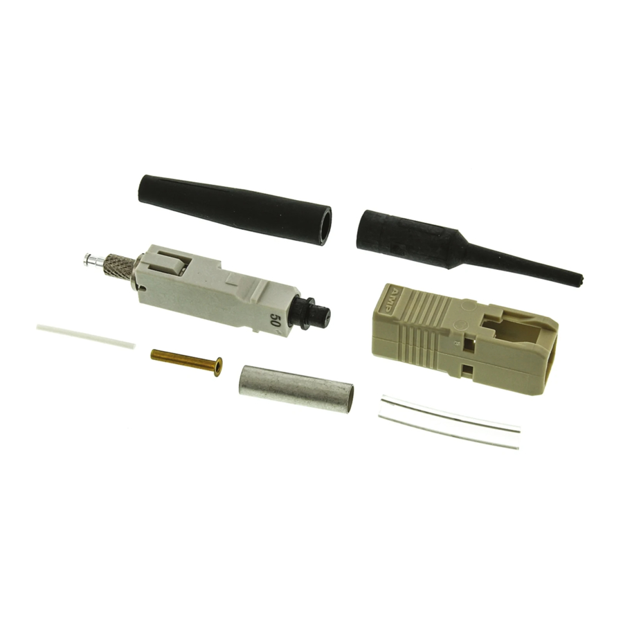
Crimp
Eyelet
Plunger
Dust Cap
Connector kit is shipped with these installed onto connector
assembly. Keep them in place until ready for assembly.
Figure 1
5.4. 900-mm Easy Strip or Semi- Tight Bu ered Fiber
Read these instructions thoroughly before assembling
the connector kits.
NOTE
Reasons for reissue of this instruction sheet are
provided in Section 6, REVISION SUMMARY.
2. DESCRIPTION
Each connector kit consists of a connector housing,
connector assembly, strain relief, inner eyelet, crimp
eyelet, and clear tubing. Each kit is also supplied with
a bare bu er boot and small tubing to compensate for
small diameter cable. Also included, assembled onto
the connector, are a termination cover for the ferrule
(front of connector) and a plunger dust cap for the
plunger (rear of connector).
©2017 CommScope, Inc.
All Rights Reserved
Strain
Relief
Inner
Eyelet
Small
Tubing
Connector
Housing
All numerical values in this instruction sheet are
in metric units. Dimensions are in millimeters.
i
Figures are for reference only and are not drawn
to scale.
(See Figure 1)
This product is covered by one or more U.S.
patents or their foreign equivalents. For patents, see
www.commscope.com/ProductPatent/ProductPatent.aspx
Instruction Sheet
408--4471
FEB 2017 Rev N
Bare Bu er
Boot
Clear
Tubing
1 of 17
Advertisement

Related Manuals for CommScope LightCrimp Plus SC Simplex


Summary of Contents for CommScope LightCrimp Plus SC Simplex
- Page 1 (result of the bu er pull test). plunger (rear of connector). ©2017 CommScope, Inc. To obtain information on CommScope ® products, visit our website at This product is covered by one or more U.S. All Rights Reserved patents or their foreign equivalents. For patents, see www.commscope.com/SupportCenter...
-
Page 2: Safety Precautions
408- 4471 3. SAFETY PRECAUTIONS 5. ASSEMBLY PROCEDURE To avoid personal injury, ALWAYS wear eye DANGER protection when working with optical bers. 900-m m Bare Bu ered Fiber 5.1. NEVER look into the end of terminated or unterminated bers. Laser radiation is invisible but can damage eye tissue. - Page 3 408- 4471 B. Cleaving 4. Squeeze the handles of the hand tool until the (Figure 3) ratchet releases. Allow the handles to open fully. 1. Open the ber clamp of the ber optic cleaver. Then: Press the button, and slide the carriage back If using Die Set 492783--1, slowly close the (toward the ber clamp).
- Page 4 408- 4471 B. Cleaving (Figure 3) 250-m m Coated Fiber 5.2. 1. Open the ber clamp of the ber optic cleaver. Press the button, and slide the carriage back Kit Components Required (toward the ber clamp). Then move the ber slide (Discard Other Components) back until it stops.
- Page 5 408- 4471 7. Position the plunger of the connector assembly 3. If using Die Set 492783--1, remove (and retain) the termination cover. in the rst (smallest) cavity of the front die with the knurl against the edge of the groove in the die and If using Die Set 1985766--1, do not remove the the ferrule or termination cover pointing in the termination cover.
- Page 6 408- 4471 Figure 2: Preparing the Fiber Figure 3: Cleaving Detail A Detail A Stripped Fiber in Slot Bu er(900--mm Bare Fiber)or Fiber(250--mm Coated Fiber) Small Diameter End of Bare Bu er Boot For 250-- m m Small Coated Fiber Tubing Plunger Detail B...
- Page 7 408- 4471 Figure 4: Crimping Figure 5: Crimping Detail A Detail A Bu er(900--mm Bare Fiber)or Fiber(250--mm Coated Fiber) Held in Cable Clamp Plunger in First Cavity of Front Die Cleaved End of Fiber Even with Front of Arm of Cable Holder Assembly Knurl Against Edge of Groove in Die...
- Page 8 408- 4471 8. Slide the bu er into the channel marked 2.5- to 3.0- mm Loose Jacketed Cable 5.3. “BUFFER” on the cable holder assembly. Make sure that the tip of the bu er butts against the end of the channel. See Figure 7, Detail C. Kit Components Required (Discard Other Components) 9.
- Page 9 408- 4471 Make sure that a space of 3 to 5 mm exists 2. Carefully insert the bu er into the plunger of the CAUTION connector assembly until the ber bottoms against between the face of the inner eyelet (shown in the internal ber.
- Page 10 408- 4471 Figure 6: Preparing the Cable Figure 7: Preparing the Cable Detail A Detail A Small Diameter End Cable Crimp Eyelet of Strain Relief Over Strength Members Detail B Inner Eyelet Under Strength Members Detail B Mark Cable at Front of Right--Most Cross--Slot Crimp Eyelet...
- Page 11 408- 4471 Figure 8: Cleaving Figure 9: Crimping Detail A Detail A Stripped Bu er in Slot Bu er Held in Cable Clamp Cleaved End of Fiber Even with Front of Arm of Cable Holder Assembly End of Fiber at 8--mm Marking Detail B Termination Cover...
- Page 12 408- 4471 Figure 10: Crimping Figure 11: Crimping Detail A Detail A Crimp Eyelet Against Last Cavity of Front Die with Ferrule Pointing in Direction of Arrow Cable Straight and Aligned with Plunger 3--5 mm Connector Assembly Space Against Die Inner Eyelet Aligned with Right--Most Mark on Bu er...
- Page 13 408- 4471 900-m m Easy Strip or Semi- Tight Bu ered Fiber 5.4. Kit Components Required Strain Inner (Discard Other Components) Relief Eyelet Crimp Eyelet Plunger Dust Cap Connector Clear Assembly Small Tubing Tubing Termination Cover Connector Housing Connector kit is shipped with these installed onto connector assembly.
- Page 14 408- 4471 C. Crimping 7. Position the plunger of the connector assembly (Figures 14 and 15) in the rst (smallest) cavity of the front die with the Only use Die Set 492783- - 1 to terminate 900- - mm knurl against the edge of the groove in the die and easy strip or semi- - tight bu ered ber.
- Page 15 408- 4471 Figure 12: Preparing the Fiber Figure 13: Cleaving Clear Detail A Detail A Circumferential Stripped Fiber in Slot Tubing Line 4 mm Inner Eyelet Small Diameter Detail B End of Strain Relief Bu er Tube Crimp Eyelet Small Tubing Detail C Plunger...
- Page 16 408- 4471 Figure 14: Crimping Figure 15: Crimping Detail A Detail A Fiber Held in Cleaved End of Fiber Cable Clamp Even with Front of Arm of Cable Holder Assembly Clear Tubing Circumferential Line End of Crimp Eyelet Detail B Detail B Crimp Eyelet Against Last Cavity of Front Die with...
-
Page 17: Revision Summary
Revisions to this instruction sheet include: inspect the ferrule end face for cleanliness using Updated document to corporate requirements. 200 ¢ Microscope Kit 1754767--1 (includes 2.5--mm adapter cap). Rebranded to CommScope® DANGER: Never View Active Fiber Signals Rev N 17 of 17...
Need help?
Do you have a question about the LightCrimp Plus SC Simplex and is the answer not in the manual?
Questions and answers