Advertisement
Quick Links
Verify that Instruction Sheet
(408- Series)
Pertains to Connector Kit
Being Terminated
To Verify, Refer to Product Drawing for
Applicable Instruction Sheet at:
www.commscope.com
(Search by Connector Kit Part Number,
Click on the Part Number
Click on Product Drawing)
1. INTRODUCTION
LightCrimp Plus ST ber optic connector kits are
designed for use with 125--m m singlemode or
multimode glass ber optic cable. These kits can be
used with any of the following media (paragraph of
assembly procedure is indicated next to media).
5.1. 900- mm Bare Bu ered Fiber
5.2. 250-mm Coated Fiber
5.3. 2.0- to 3.0- mm Loose Jacketed Cable
5.4. 900- mm Easy Strip or Semi- Tight Bu ered Fiber
Read these instructions thoroughly before assembling
the connector kits.
All numerical values in this instruction sheet
NOTE
are in metric units. Dimensions are in
i
millimeters Figures are not drawn to scale.
Reasons for reissue of this instruction sheet are
provided in Section 6, REVISION SUMMARY.
To obtain information on CommScope ® products, visit our website at
www.commscope.com/SupportCenter
LightCrimp Plus® ST
Fiber Optic Connector Kits
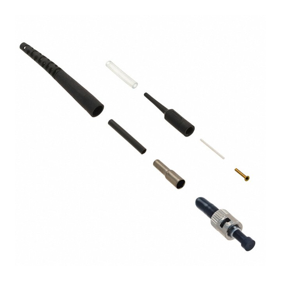
Black
Tubing
Connector
,
Assembly
Ferrule Protective
Cover
Bare Bu er
Boot
Small
Tubing
Inner
Eyelet
Plunger
Protective Cap
Connector kit is shipped with these installed onto connector
assembly. Keep them in place until ready for assembly.
Figure 1
2. DESCRIPTION
(See Figure 1)
Each connector kit consists of a connector assembly,
strain relief, inner eyelet, crimp eyelet, black tubing,
and clear tubing. Each kit is also supplied with a bare
bu er boot and small tubing to compensate for small
diameter cable. Also included, assembled onto the
connector, is a ferrule protective cover for the ferrule
(front of connector) and a plunger protective cap for
the plunger (rear of connector).
3. SAFETY PRECAUTIONS
NEVER look into the end of terminated or
DANGER
unterminated bers. Laser radiation is invisible
but can damage eye tissue. NEVER eat, drink, or
smoke when working with bers. This could lead
to ingestion of glass particles.
Be very careful to dispose o
DANGER
The bers create slivers that can easily puncture
the skin and cause irritation.
DO NOT use defective or damaged components.
CAUTION
Replace them with new components.
!
©2017 CommScope, Inc.
All Rights Reserved
Instruction Sheet
408--4457
FEB 2017
Clear
Crimp
Tubing
Eyelet
ber ends properly.
This product is covered by one or more U.S.
patents or their foreign equivalents. For patents, see
www.commscope.com/ProductPatent/ProductPatent.aspx
Rev J
Strain
Relief
1 of 16
Advertisement

Related Manuals for CommScope LightCrimp Plus ST


Summary of Contents for CommScope LightCrimp Plus ST
- Page 1 Reasons for reissue of this instruction sheet are provided in Section 6, REVISION SUMMARY. ©2017 CommScope, Inc. To obtain information on CommScope ® products, visit our website at This product is covered by one or more U.S. All Rights Reserved patents or their foreign equivalents.
-
Page 2: Required Tools And Materials
— Fiber Optic Cleaver 1871696--1 (408--10086) Only use isopropyl alcohol on the tool. — LightCrimp Plus ST Die Set with Crimping Tool 492623--1 (consists of Die Set 492622--1 and B. Cleaving (Figure 3) PRO--CRIMPER®... - Page 3 408- 4457 Make sure that the ber does not pull rearward NOTE 250- mm Coated Fiber 5.2. from the contact (with the internal ber) during the crimping operation. Kit Components Required Plunger (Discard Other Components) 3. Squeeze the handles of the hand tool until the Protective ratchet releases.
- Page 4 408- 4457 (toward the ber clamp). Then move the ber slide 3. Squeeze the tool handles of the hand tool until back until it stops. the ratchet releases. Allow the handles to open fully. Slowly close the handles until you hear three 2.
- Page 5 408- 4457 Figure 2: Preparing the Fiber Figure 3: Cleaving Detail A Detail A Stripped Fiber in Slot Bu er(900-- m m Bare Fiber) or Fiber(250--mm Small Diameter End Coated Fiber) of Bare Bu er Boot Small For 250-- m m Tubing Coated Fiber Plunger...
- Page 6 408- 4457 Figure 4: Crimping Figure 5: Crimping Detail A Detail A Ferrule in Upper Cavity of Front Die and Pointing in Bu er(900-- m m Bare Fiber) o r Direction of Arrow Fiber(250--m m Coated Fiber) Held in Cable Clamp Cleaved End of Fiber Even with Front of Arm of Cable Holder...
- Page 7 408- 4457 scissors, cut the strength members even with the 2.0- to 3.0- mm Jacketed Cable 5.3. jacket. Then, remove the remaining jacket segment. See Figure 6, Detail D. 7. If the cable outside diameter is 2.5 mm or larger, Kit Components Required slide the crimp eyelet onto the bu er and, using the (Discard Other Components)
- Page 8 408- 4457 DO NOT attempt to clean the ber after it has 5. Gently push the bu er toward the connector to CAUTION been cleaved. make sure that the ber is still bottomed, then slowly squeeze the tool handles together until the ratchet releases.
- Page 9 408- 4457 Figure 6: Preparing the Cable Figure 7: Preparing the Cable Detail A Detail A Small Diameter End Small Diameter of Crimp Eyelet End of Strain Cable Relief Strength Members Folded Over Jacket Black Tubing Detail B For 2.0-- to 2.4--mm Jacketed Cable Detail B Mark Jacket at...
- Page 10 408- 4457 Figure 8: Cleaving Figure 9: Crimping Detail A Detail A Stripped Fiber in Slot Bu er Held in Cable Clamp Cleaved End of Fiber Even with Front of Arm of Cable Holder Detail B End of Bu er at Ferrule Facing 8--mm Marking Outward...
- Page 11 408- 4457 Figure 10: Crimping Figure 11: Crimping Detail A Detail A Plunger in First Cavity of Front Die with Ferrule Pointing in Direction of Arrow Shoulder of Plunger Against Edge of Groove in Die Large Diameter End of Crimp Eyelet in Last Cavity of Front Die with Ferrule Pointing in Direction of Arrow...
- Page 12 408- 4457 900-m m Easy Strip or Semi- Tight Bu ered Fiber 5.4. Kit Components Required Small (Discard Other Components) Tubing Inner Eyelet Strain Relief Connector Assembly Ferrule Crimp Protective Eyelet Clear Cover Tubing Plunger Protective Connector kit is shipped with these installed onto connector assembly.
- Page 13 408- 4457 DO NOT attempt to clean the ber after it has crushed when the tool is actuated. See Figure 15, CAUTION been cleaved. Detail A. The arrows marked on the front die indicate the CAUTION direction that the ferrule protective cover must be pointing when the connector is positioned in that C.
- Page 14 408- 4457 Figure 12: Preparing the Fiber Figure 13: Cleaving Detail A Detail A Stripped Fiber in Slot Clear Tubing Inner Eyelet Detail B Small Diameter End of Strain Relief Fiber Small Tubing Detail C Plunger End of Bu er at 8--mm Marking Detail D Mark Fiber at...
- Page 15 408- 4457 Figure 14: Crimping Figure 15: Crimping Figure 15: Crimping Detail A Detail A Ferrule in Upper Cavity of Fiber(Break--Out)or Bu er Front Die and Pointing in (Easy Strip or Semi--Tight) Direction of Arrow Held in Cable Clamp Cleaved End of Fiber Even with Front of Arm of Cable Holder Plunger in Upper...
-
Page 16: Revision Summary
Figure 16: Crimping Revisions to this instruction sheet include: Detail A Updated document to corporate requirements. Large Diameter End of Rebranded to CommScope® Crimp Eyelet in Last Cavity of Front Die with Ferrule Pointing in Direction of Arrow Detail B...
Need help?
Do you have a question about the LightCrimp Plus ST and is the answer not in the manual?
Questions and answers