
Related Manuals for Satel AOD-200


Summary of Contents for Satel AOD-200
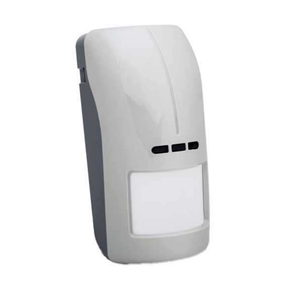
- Page 1 04/17 WIRELESS OUTDOOR DUAL TECHNOLOGY MOTION DETECTOR AOD-200 Firmware version 1.0 SATEL sp. z o.o. • ul. Budowlanych 66 • 80-298 Gdańsk • POLAND tel. +48 58 320 94 00 www.satel.eu...
- Page 2 Rating plate of the device can be found on the rear side of the electronics module. SATEL's goal is to continually upgrade the quality of its products, which may result in some changes of their technical specifications and firmware. The current information on the introduced modifications is available on our website.
- Page 3 The AOD-200 outdoor detector allows detection of motion in the protected area. The detector is designed for use as part of the ABAX two-way wireless system. This manual applies to the detector with electronics version 1.1 (or newer) and firmware version 1.0 (or newer). The detector is supported by: ...
- Page 4 AOD-200 SATEL Light intensity [lx] Detection threshold Turning on [P Turning off [P Table 1 Operating modes The detector operating mode has an effect on operation of the motion sensors. Switching between the operating modes is done remotely. Active mode – motion detection alarm or tamper alarm can be triggered. The microwave sensor activates after motion is detected by the infrared sensor.
-
Page 5: Electronics Module
SATEL AOD-200 alarm – the red LED is ON for 2 seconds. Supervision of detector signal path In case of signal path failure, the detector sends information about alarm during each transmission (constant violation). Battery status control When the battery voltage is below 2.75 V, information about low battery is sent during each transmission. - Page 6 AOD-200 SATEL Be particularly careful during installation and replacement of the battery. The manufacturer is not liable for the consequences of incorrect installation of the battery. The used batteries must not be discarded, but should be disposed of in accordance with the existing rules for environment protection.
- Page 7 SATEL AOD-200 2. Install the battery and secure it with the clip you will find in the package. 3. Add the detector to the wireless system (see the ACU-120 / ACU-270 controller manual or the INTEGRA 128-WRL / VERSA / VERSA Plus / VERSA IP control panel installer manual).
- Page 8 AOD-200 SATEL Angle bracket mounting 1. Attach extra tamper switch: – screw the holder to the tamper switch (Fig. 7-I), – screw the tamper unit to the enclosure base (Fig. 7-III). Figure 7 shows mounting the tamper switch in one of two available positions. The place of tamper switch installing depends on the way of angle bracket mounting.
- Page 9 SATEL AOD-200 3. Using wall plugs (screw anchors) and screws, fasten the ball bracket to the wall (Fig. 8- IV). 4. Run the tamper switch wires through the hole made in the enclosure base and connect them to the TMP terminals.
-
Page 10: Specifications
AOD-200 SATEL Connecting the additional tamper switch The additional tamper switch is provided with three wires: – black – common wire, – blue – wire for NC circuit, – grey – wire for NO circuit. 5. Specifications Operating frequency band..............868.0 MHz ÷ 868.6 MHz Radio communication range (in open area) ............
Need help?
Do you have a question about the AOD-200 and is the answer not in the manual?
Questions and answers