Table of Contents
Advertisement
Instructions – Parts List
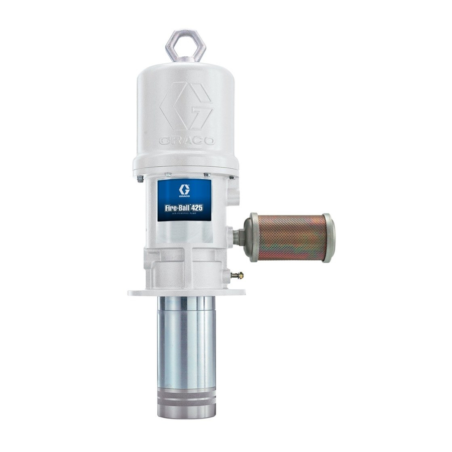
6:1 Fire–Ball
For pumping non–corrosive and
non–abrasive oils and lubricants only.
Model 238108, Series D
1100 psi (7.6MPa, 76 bar) Maximum Working Pressure
180 psi (1.2 MPa, 12 bar) Maximum Air Input Pressure
Important Safety instructions
Read all warnings and instructions in this manual.
Save these instructions.
GRACO INC. P.O. BOX 1441 MINNEAPOLIS, MN 55440-1441
Copyright 1995, Graco Inc. is registered to I.S. EN ISO 9001
r
425 Pump
308608K
06031
Advertisement
Table of Contents

Related Manuals for Graco Fire-Ball D Series


Summary of Contents for Graco Fire-Ball D Series
- Page 1 180 psi (1.2 MPa, 12 bar) Maximum Air Input Pressure Important Safety instructions Read all warnings and instructions in this manual. Save these instructions. 06031 GRACO INC. P.O. BOX 1441 MINNEAPOLIS, MN 55440-1441 Copyright 1995, Graco Inc. is registered to I.S. EN ISO 9001...
-
Page 2: Table Of Contents
D This equipment is for professional use only. D Read all instruction manuals, tags, and labels before operating the equipment. D Use the equipment only for its intended purpose. If you are not sure, call your Graco distributor. D Do not alter or modify this equipment. - Page 3 WARNING WARNING SKIN INJECTION HAZARD Fluid from the dispensing valve, leaks or ruptured components can inject fluid into your body and cause extremely serious injury, including the need for amputation. Fluid splashed in the eyes or on the skin can also cause serious injury. D Fluid injected into the skin may look like just a cut, but it is a serious injury.
- Page 4 WARNING WARNING FIRE AND EXPLOSION HAZARD Improper grounding, poor ventilation, open flames or sparks can cause a hazardous condition and result in a fire or explosion and serious injury. D Ground the equipment. Refer to Grounding on page 7. D If there is any static sparking or you feel an electric shock while using this equipment, stop dispensing immediately.
-
Page 5: Installation
Contact your Graco representative or Always mount the pump firmly to a bracket or a your Graco distributor for assistance in designing a tank cover. Never operate the pump while it is not system to suit your needs. - Page 6 Installation System Accessories 1. Screw the muffler (5) into the 3/4-in. npt muffler port, and tighten it using a wrench on the flats of the muffler near the male threads. CAUTION 2. Install an air line lubricator (N) for automatic air Do not hang the air accessories directly on the air motor lubrication.
- Page 7 Installation Grounding To ground the pump, remove the ground screw (Z) and insert through the eye of the ring terminal at end of Proper grounding is an essential part of maintaining a the ground wire (Y). Fasten the ground screw back onto safe system.
-
Page 8: Operation
Operation Pressure Relief Procedure WARNING WARNING HAZARDOUS VAPORS The air motor exhaust coming out of the SKIN INJECTION HAZARD muffler could contain harmful materials, To reduce the risk of serious bodily such as oil, antifreeze, or some of the injury, including fluid injection or splash- material being pumped. -
Page 9: Troubleshooting
Operation 7. Read and follow the instructions supplied with 8. If the pump will be unattended for any period of each component in your system. time, if there is an air supply interruption, or to shut off the system at the end of the work shift, always relieve the pressure. -
Page 10: Air Motor And Throat Service
Air Motor and Throat Service Before You Start 9. Remove the eight screws (3) holding the cylinder (30) to the base (28). Carefully pull the cylinder D Be sure you have all necessary parts on hand. straight up off of the piston assembly (27). Air Motor Repair Kit 207385 includes repair parts for the motor. - Page 11 Air Motor and Throat Service 10. Pull the piston assembly from the air motor base 15. In this step, while you are prying with the screw- (28), and set it aside. driver with one hand, cover the toggle assemblies with your other hand so as to catch the spring- loaded toggle assemblies when they snap out of 11.
- Page 12 Air Motor and Throat Service Cut off tops of poppets as indicated by dotted lines. Turn lock- wires 0.125” (3.18 mm) 04422 Cutaway View 05612 Fig. 4 Reassembly 1. Place the piston rod (29) flats in the vice with the 7.
- Page 13 Air Motor and Throat Service 12. Grease and reinstall the u-cup seal (10 ), thread 16. Install the u-cup packing (107 ) with the lips up, the throat bearing (36) into the air motor base (28), and place the piston washer (113) on the piston/ and torque the throat bearing to 30 to 40 ft-lb valve seat (109).
-
Page 14: Displacement Pump Service
Displacement Pump Service Disassembly Displacement Pump. See Fig 5. NOTE: Clean and inspect all parts for wear or damage NOTE: Displacement Pump Repair Kit 238225 as you disassemble them. Replace parts as includes repair parts for the pump throat and needed. -
Page 15: Displacement Pump Parts Drawing And List
Displacement Pump Parts Drawing and List Model 238108, Series D Air motor not listed or shown here. See pages 16 and 17. Part No. Description Qty. Part No. Description Qty. 194016 PISTON 113345 SEAL, u-cup (shown on page 16) 1 190922 CYLINDER, pump 101190... -
Page 16: Air Motor Parts Drawing
Air Motor Parts Drawing See Displacement Pump Parts Drawing and List on page 15. 06032 Torque to 30 to 40 ft-lb (41 to 54 N.m). Lips must face down. 308608K... -
Page 17: Air Motor Parts List
Air Motor Parts List Part No. Description Qty. Part No. Description Qty. 190929 RING, lift 101578 SCREW, cap, hex hd 167585 SPRING, helical compression 102656 MUFFLER, air exhaust 170709 POPPET, exhaust valve 116343 SCREW, ground 207391 PISTON, includes items 27a to 27c 113345 SEAL, u-cup (also includes 207385 repair kit when... -
Page 18: Mounting Hole Layout
Dimensions Mounting Hole Layout MODEL 238108 Pump, Series D 3.0-in. (76.2-mm) diameter clearance hole Four 1/4–20 UNC-2B tapped depth 1.25-in (31.7-mm) on 4.25-in (108-mm) diameter bolt 3/4-in. 1/2-in. circle npt fluid npt air outlet inlet Four 0.406-in. (10.3-mm) diameter holes on 7-in. 26.4 in. -
Page 19: Performance Charts
Performance Charts To find Fluid Outlet Pressure (psi/bar) at a specific fluid flow (gpm/lpm) and operating air pressure (psi/bar): 1. Locate desired fluid flow along bottom of chart. 2. Follow vertical line up to point of intersection with selected fluid outlet pressure curve. 2. -
Page 20: Warranty
With the exception of any special, extended, or limited warranty published by Graco, Graco will, for a period of twelve months from the date of sale, repair or replace any part of the equipment determined by Graco to be defective.
Need help?
Do you have a question about the Fire-Ball D Series and is the answer not in the manual?
Questions and answers